Framework System Design Description
Introduction
Frameworks are a software development construct aiming to simplify the creation of specific classes of applications through abstraction of low-level details. The main object of creating a framework is to provide an interface to application developers that saves time and provides advanced capabilities not attainable otherwise. The Multiphysics Object Oriented Simulation Environment (MOOSE), mission is just that: provide a framework for engineers and scientists to build state-of-the-art, computationally scalable finite element based simulation tools.
MOOSE was conceived with one major objective: to be as easy and straightforward to use by scientists and engineers as possible. MOOSE is meant to be approachable by non-computational scientists who have systems of PDEs they need to solve. Every single aspect of MOOSE was driven by this singular principle from the build system to the API to the software development cycle. At every turn, decisions were made to enable this class of users to be successful with the framework. The pursuit of this goal has led to many of the unique features of MOOSE:
A streamlined build system
An API aimed at extensible
Straightforward APIs providing sensible default information
Integrated, automatic, and rigorous testing
Rapid, continuous integration development cycle
Codified, rigorous path for contributing
Applications are modular and composable
Each of these characteristics is meant to build trust in the framework by those attempting to use it. For instance, the build system is the first thing potential framework users come into contact with when they download a new software framework. Onerous dependency issues, complicated, hard to follow instructions or build failure can all result in a user passing on the platform. Ultimately, the decision to utilize a framework comes down to whether or not you trust the code in the framework and those developing it to be able to support your desired use-case. No matter the technical capabilities of a framework, without trust users will look elsewhere. This is especially true of those not trained in software development or computational science.
Developing trust in a framework goes beyond utilizing "best practices" for the code developed, it is equally important that the framework itself is built upon tools that are trusted. For this reason, MOOSE relies on a well-established code base of libMesh and PETSc. The libMesh library provides foundational capability for the finite element method and provides interfaces to leading-edge numerical solution packages such as PETSc.
With these principles in mind, an open source, massively parallel, finite element, multiphysics framework has been conceived. MOOSE is an on-going project started in 2008 aimed toward a common platform for creation of new multiphysics tools. This document provides design details pertinent to application developers as well as framework developers.
Use Cases
The MOOSE Framework is targeted at two main groups of actors: Developers and Users. Developers are the main use case. These are typically students and professionals trained in science and engineering fields with some level of experience with coding but typically very little formal software development training. The other user group is Users. Those who intend to use an application built upon the framework without writing any computer code themselves. Instead they may modify or create input files for driving a simulation, run the application, and analyze the results. All interactions through MOOSE are primarily through the command-line interface and through a customizable block-based input file.
System Purpose
The Software Design Description provided here is description of each object in the system. The pluggable architecture of the framework makes MOOSE and MOOSE-based applications straightforward to develop as each piece of end-user (developer) code that goes into the system follows a well-defined interface for the underlying systems that those object plug into. These descriptions are provided through developer-supplied "markdown" files that are required for all new objects that are developed as part of the framework, modules and derivative applications. More information about the design documentation can be found in MooseDocs.
System Scope
The purpose of this software is to provide several libraries that can be used to build an application based upon the framework. Additionally, several utilities are provided for assisting developers and users in end-to-end Finite Element Method (FEM) analysis. A brief overview of the major components are listed here:
| Component | Description |
|---|---|
| framework library | The base system from which all MOOSE-based applications are created |
| module libraries | Optional "physics" libraries that may be used in an application to provide capability |
| build system | The system responsible for creating applications for a series of libraries and applications |
| test harness | The extendable testing system for finding, scheduling, running, and reporting regression tests |
| "peacock" | The graphical user interface (GUI) for building input files, executing applications, and displaying results |
| MooseDocs | The extendable markdown system for MOOSE providing common documentation and requirements enforcement |
| "stork" | The script and templates for generating a new MOOSE-based application ready for building and testing |
| examples | A set of complete applications demonstrating the use of MOOSE's pluggable systems |
| tutorials | Step by step guides to building up an application using MOOSE's pluggable systems |
| unit | An application for unit testing individual classes or methods of C++ code |
Dependencies and Limitations
The MOOSE platform has several dependencies on other software packages and has scope that is constantly evolving based upon funding, resources, priorities, and lab direction. However, the software is open-source and many features and even bugs can be offloaded to developers with appropriate levels of knowledge and direction from the main design team. The primary list of software dependencies is listed below. This list is not meant to be exhaustive. Individual operating systems may require specific packages to be installed prior to using MOOSE, which can be found on the Getting Started pages.
| Software Dependency | Description |
|---|---|
| libMesh | Finite Element Library and I/O routines |
| PETSc | Solver Package |
| hypre | Multigrid Preconditioner |
| MPI | A distributed parallel processing library (MPICH) |
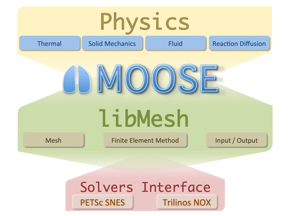
Figure 1: A diagram of the MOOSE code platform.
References
- ISO/IEC/IEEE 24765:2010(E).
Systems and software engineering—Vocabulary.
first edition, December 15 2010.[BibTeX]
- D. F. Griffiths.
The `No Boundary Condition' outflow boundary condition.
International Journal of Numerical Methods in Fluids, 24(4):393–411, 1997.
URL: http://tinyurl.com/y77au2k.[BibTeX]
- ASME NQA-1.
ASME NQA-1-2008 with the NQA-1a-2009 addenda: Quality Assurance Requirements for Nuclear Facility Applications.
first edition, August 31 2009.[BibTeX]
Definitions and Acronyms
This section defines, or provides the definition of, all terms and acronyms required to properly understand this specification.
Definitions
Pull (Merge) Request: A proposed change to the software (e.g. usually a code change, but may also include documentation, requirements, design, and/or testing).
Baseline: A specification or product (e.g., project plan, maintenance and operations (M&O) plan, requirements, or design) that has been formally reviewed and agreed upon, that thereafter serves as the basis for use and further development, and that can be changed only by using an approved change control process (NQA-1, 2009).
Validation: Confirmation, through the provision of objective evidence (e.g., acceptance test), that the requirements for a specific intended use or application have been fulfilled (24765:2010(E), 2010).
Verification: (1) The process of: evaluating a system or component to determine whether the products of a given development phase satisfy the conditions imposed at the start of that phase. (2) Formal proof of program correctness (e.g., requirements, design, implementation reviews, system tests) (24765:2010(E), 2010).
Acronyms
| Acronym | Description |
|---|---|
| AD | automatic differentiation |
| API | Application Programming Interface |
| CIVET | Continuous Integration for Verification, Enhancement, and Testing |
| DOE | Department of Energy |
| DOE-NE | Department of Energy, Nuclear Energy |
| DOF | degree-of-freedom |
| FE | Finite Element |
| FEM | Finite Element Method |
| GUI | graphical user interface |
| HIT | Hierarchical Input Text |
| HPC | High Performance Computing |
| I/O | Input/Output |
| INL | Idaho National Laboratory |
| JFNK | Jacobian-Free Newton-Krylov |
| LGPL | GNU Library General Public License |
| MMS | Method of Manufactured Solutions |
| MPI | Method Passing Interface |
| MOOSE | Multiphysics Object Oriented Simulation Environment |
| NE | Nuclear Energy |
| NQA-1 | Nuclear Quality Assurance Level 1 |
| PETSc | Portable, Extensible Toolkit for Scientific Computation |
| POSIX | Portable Operating System Interface |
| PDE | partial differential equation |
| PDEs | partial differential equations |
| RTM | Requirement Traceability Matrix |
| SDD | Software Design Description |
| SRS | Software Requirement Specification |
| STP | Software Test Plan |
| VVR | Verification and Validation Report |
Design Stakeholders and Concerns
Design Stakeholders
Stakeholders for MOOSE include several of the funding sources including Department of Energy, Nuclear Energy (DOE-NE) and the Idaho National Laboratory (INL). However, Since MOOSE is an open-source project, several universities, companies, and foreign governments have an interest in the development and maintenance of the MOOSE project.
Stakeholder Design Concerns
Concerns from many of the stakeholders are similar. These concerns include correctness, stability, and performance. The mitigation plan for each of these can be addressed. For correctness, MOOSE development requires either regression or unit testing for all new code added to the repository. The project contains several comparisons against analytical solutions where possible and also other verification methods such as MMS. For stability, MOOSE maintains multiple branches to incorporate several layers of testing both internally and for dependent applications. Finally, performance tests are also performed as part of the the normal testing suite to monitor code change impacts to performance.
System Design
The MOOSE framework itself is composed of a wide range of pluggable systems. Each system is generally composed of a single or small set of C++ objects intended to be specialized by a Developer to solve a specific problem. To accomplish this design goal, MOOSE uses several modern object-oriented design patterns. The primary overarching pattern is the "Factory Pattern". Users needing to extend MOOSE may inherit from one of MOOSE's systems to providing an implementation meeting his or her needs. The design of each of these systems is documented on the mooseframework.org wiki in the Tutorial section. Additionally, up-to-date documentation extracted from the source is maintained on the the mooseframework.org documentation site after every successful merge to MOOSE's stable branch. After these objects are created, the can be registered with the framework and used immediately in a MOOSE input file.
System Structure
The MOOSE framework architecture consists of a core and several pluggable systems. The core of MOOSE consists of a number of key objects responsible for setting up and managing the user-defined objects of a finite element simulation. This core set of objects has limited extendability and exist for every simulation configuration that the framework is capable of running.
Available Subsystems
- Moose App
- Adaptivity
- AuxKernels
- AuxScalarKernels
- AuxVariables
- BCs
- Constraints
- Controls
- DGKernels
- Dampers
- Debug
- DeprecatedBlock
- DiracKernels
- Distributions
- Executioner
- Functions
- GlobalParams
- ICs
- InterfaceKernels
- Kernels
- Materials
- Mesh
- MeshGenerators
- MeshModifiers
- MultiApps
- NodalKernels
- NodalNormals
- Outputs
- Postprocessors
- Preconditioning
- Problem
- ReactionNetwork
- Samplers
- ScalarKernels
- Transfers
- UserObjects
- Variables
- VectorPostprocessors
- Heat Conduction App
- BCs
- Constraints
- DiracKernels
- GrayDiffuseRadiation
- InterfaceKernels
- Kernels
- Materials
- Mesh
- MeshGenerators
- Postprocessors
- ThermalContact
- UserObjects
- VectorPostprocessors
- Solid Mechanics App
- AuxKernels
- Kernels
- Materials
- Postprocessors
- UserObjects
- VectorPostprocessors
- Contact Test App
- Constraints
- Heat Conduction Test App
- Materials
- Navier Stokes App
- AuxKernels
- AuxVariables
- BCs
- Functions
- ICs
- Kernels
- Materials
- Modules
- Postprocessors
- UserObjects
- Variables
- Porous Flow App
- AuxKernels
- AuxVariables
- BCs
- DiracKernels
- Functions
- ICs
- Kernels
- Materials
- PorousFlowBasicTHM
- PorousFlowFullySaturated
- PorousFlowUnsaturated
- Postprocessors
- UserObjects
- Variables
- Stochastic Tools App
- Controls
- Distributions
- MultiApps
- Samplers
- Transfers
- VectorPostprocessors
- XFEMTest App
- Kernels
- Postprocessors
- UserObjects
- Rdg Test App
- UserObjects
- Contact App
- AuxKernels
- Constraints
- Contact
- Dampers
- DiracKernels
- Postprocessors
- Preconditioning
- Problem
- UserObjects
- Functional Expansion Tools App
- AuxKernels
- BCs
- Functions
- Transfers
- UserObjects
- Phase Field Test App
- AuxKernels
- Kernels
- Materials
- Navier Stokes Test App
- Kernels
- Peridynamics Test App
- Materials
- Tensor Mechanics Test App
- Materials
- UserObjects
- Misc App
- AuxKernels
- Kernels
- Materials
- Postprocessors
- UserObjects
- Stochastic Tools Test App
- Postprocessors
- UserObjects
- Misc Test App
- Kernels
- Materials
- Richards App
- AuxKernels
- BCs
- DiracKernels
- Functions
- Kernels
- Materials
- Postprocessors
- Problem
- UserObjects
- Level Set App
- Functions
- Kernels
- MultiApps
- Postprocessors
- Problem
- Transfers
- UserObjects
- External Petsc Solver App
- Mesh
- Problem
- Fluid Properties App
- AuxKernels
- FluidPropertiesInterrogator
- Materials
- Modules
- UserObjects
- Rdg App
- BCs
- DGKernels
- Materials
- Postprocessors
- UserObjects
- XFEMApp
- AuxKernels
- BCs
- Constraints
- DiracKernels
- Kernels
- Materials
- UserObjects
- XFEM
- Fluid Properties Test App
- AuxKernels
- Kernels
- Materials
- Modules
- Tensor Mechanics App
- AuxKernels
- AuxScalarKernels
- AuxVariables
- BCs
- Dampers
- DomainIntegral
- ICs
- InterfaceKernels
- Kernels
- Materials
- Modules
- NodalKernels
- Postprocessors
- ScalarKernels
- UserObjects
- Variables
- VectorPostprocessors
- Phase Field App
- Adaptivity
- AuxKernels
- AuxVariables
- Functions
- ICs
- InterfaceKernels
- Kernels
- Materials
- Mesh
- MeshGenerators
- Modules
- Postprocessors
- UserObjects
- Variables
- VectorPostprocessors
- Peridynamics App
- AuxKernels
- BCs
- Kernels
- Materials
- Mesh
- MeshGenerators
- Modules
- NodalKernels
- Postprocessors
- ScalarKernels
- UserObjects
- Chemical Reactions App
- AuxKernels
- BCs
- Kernels
- Materials
- Postprocessors
- ReactionNetwork
- UserObjects
The MooseApp is the top-level object used to hold all of the other objects in a simulation. In a normal simulation a single MooseApp object is created and "run()". This object uses it's Factory objects to build user defined objects which are stored in a series of Warehouse objects and executed. The Finite Element data is stored in the Systems and Assembly object while the domain information (the Mesh) is stored in the Mesh object. A series of threaded loops are used to run parallel calculations on the objects created and stored within the warehouses.
MOOSE's pluggable systems are documented on the mooseframework.org wiki. Each of these systems has set of defined polymorphic interfaces and are designed to accomplish a specific task within the simulation. The design of these systems is fluid and is managed through agile methods and ticket request system on the Github.org website.
Data Design and Control
At a high level, the system is designed to process Hierarchical Input Text (HIT) input files to construct several objects that will constitute an Finite Element (FE) simulation. Some of the objects in the simulation may in turn load other file-based resources to complete the simulation. Examples include meshes or data files. The system will then assemble systems of equations and solve them using the libraries of the Code Platform. The system can then output the solution in one or more supported output formats commonly used for visualization.
Human-Machine Interface Design
MOOSE is a command-line driven program. All interaction with MOOSE and MOOSE-based codes is ultimately done through the command line. This is typical for High Performance Computing (HPC) applications that use the Method Passing Interface (MPI) interface for running on super computing clusters. Optional GUIs may be used to assist in creating input files and launching executables on the command line.
System Design Interface
All external system interaction is performed either through file Input/Output (I/O) or through local Application Programming Interface (API) calls. Neither the framework, nor the modules are designed to interact with any external system directly through remote procedure calls. Any code to code coupling performed using the framework are done directly through API calls either in a static binary or after loading shared libraries.
Security Structure
The framework does not require any elevated privileges to operate and does not run any stateful services, daemons or other network programs. Distributed runs rely on the MPI library.
Requirements Cross-Reference
- framework: AuxVariables System
- F1.1.1The system shall error if the supplied order of scalar auxiliary variable is of an unknown order.
Specification: actions/aux_scalar_variable:invalid_order_high
Design: AuxVariables System
- F1.1.2The system shall support calculations with an auxiliary scalar variable represented with a 21st order monomial function.
Specification: actions/aux_scalar_variable:high_order_scalar
Design: AuxVariables System
- F1.10.1The system shall support the coupling of scalar aux variables for the purpose of sharing data and reporting values.
Specification: dirackernels/aux_scalar_variable:test
Design: AuxVariables System
Issue(s): #2318
- F1.49.2The system shall support direct calculation of field variables on multiple mesh subdomains.
Specification: variables/block_aux_kernel:block_aux_kernel_test
Design: AuxVariables System
Issue(s): 76ddaa1961753020e57d62d2b8f29e0638e40c28
- framework: MOOSE Action System
- F1.1.3The system shall be capable of reporting
Actionobject dependencies.Specification: actions/debug_block:test_show_actions_dependency
Design: MOOSE Action System
Issue(s): #11971
- F1.1.4The system shall be capable of reporting
Actionobject task information.Specification: actions/debug_block:test_show_actions_tasks
Design: MOOSE Action System
Issue(s): #11971
- F1.1.5The system shall be able to retrieve other
Actionobjects from within anotherActionobject.Specification: actions/get_actions:get_actions
Design: MOOSE Action System
Issue(s): #7905
- F1.1.6The Action system shall allow
Actionobjects to create otherActionobjects.Specification: actions/meta_action:test_meta_action
Design: MOOSE Action System
Issue(s): #1478
- F1.1.7The Action system shall allow the creation of
Actionobjects with multiple tasks.Specification: actions/meta_action_multiple_tasks:circle_quads
Design: MOOSE Action System
Issue(s): #10619
- F1.1.8The Postprocessor data shall be initialized by the
SetupPostprocessorDataActionobject and thePostprocessorInterface::hasPostprocessorshall return true when called with a defined postprocessor name.Specification: actions/setup_postprocessor_data:test_pass
Design: MOOSE Action SystemPostprocessor System
Issue(s): #2407
- F1.1.9The system
PostprocessorInterface::hasPostprocessormethod shall return false when called with an undefined postprocessor name.Specification: actions/setup_postprocessor_data:test_failure
Design: MOOSE Action SystemPostprocessor System
Issue(s): #2407
- framework: Postprocessor System
- F1.1.8The Postprocessor data shall be initialized by the
SetupPostprocessorDataActionobject and thePostprocessorInterface::hasPostprocessorshall return true when called with a defined postprocessor name.Specification: actions/setup_postprocessor_data:test_pass
Design: MOOSE Action SystemPostprocessor System
Issue(s): #2407
- F1.1.9The system
PostprocessorInterface::hasPostprocessormethod shall return false when called with an undefined postprocessor name.Specification: actions/setup_postprocessor_data:test_failure
Design: MOOSE Action SystemPostprocessor System
Issue(s): #2407
- F1.3.43Execution of a UserObject shall occur after the execution of the AuxKernel objects if the former depends on the latter.
Specification: auxkernels/pp_depend:test
Design: AuxKernels SystemPostprocessor System
Issue(s): #2848
- F1.13.54The Function object shall support the ability to couple Postprocessor values.
Specification: functions/pps_function:test_pp_function_test
Design: Postprocessor System
- F1.33.17The system shall compute the average integral quantity over an element of a scalar material property.
Specification: postprocessors/element_integral_material_property:test
Design: Postprocessor System
Issue(s): #2201
- F1.33.21The system shall compute the volumetric L2 norm of a variable over the mesh.
Specification: postprocessors/element_l2_norm:test
Design: Postprocessor System
Issue(s): #2201
- F1.33.62The system shall support the ability to retrieve previously computed Postprocessor values within a Postprocessor calculation:
- old (one timestep back) and
- older (two timesteps back).
Specification: postprocessors/old_older_values:old_older
Design: Postprocessor System
Issue(s): #5117
- F1.33.76The system shall support the ability to report an input parameter on the screen or to an input file.
Specification: postprocessors/real_parameter_reporter:test
Design: Postprocessor System
- F1.33.77The system shall report an error when a requested parameter for reporting does not exist.
Specification: postprocessors/real_parameter_reporter:error_report
Design: Postprocessor System
- F1.33.81The system shall support coupling in a scalar variable to the Postprocessing system for calculating values.
Specification: postprocessors/scalar_coupled_postprocessor:test
Design: Postprocessor System
Issue(s): #7198
- F1.33.87The system shall compute an aggregate scalar quantity when applied along multiple boundaries.
Specification: postprocessors/side_pps:test_side_multi_bnd
Design: Postprocessor System
Issue(s): #828
- framework: Adaptivity System
- F1.2.1The Adaptivity system shall allow for multiple mesh adaptivity steps per timestep.
Specification: adaptivity/cycles_per_step:test
Design: Adaptivity System
Issue(s): #830
- F1.2.2The Adaptivity system shall support mesh adaptivity during initial setup.
Specification: adaptivity/initial_adapt:test
Design: Adaptivity SystemMarkers System
Issue(s): #1700
- F1.2.3The Adaptivity system shall support marking elements for refinement during initial setup using a different marker than used during execution.
Specification: adaptivity/initial_marker:test
Design: Adaptivity SystemMarkers System
Issue(s): #1700
- F1.2.4The Adaptivity system shall support execution at every n timestep.
Specification: adaptivity/interval:test
Design: Adaptivity SystemMarkers System
Issue(s): #13561
- F1.2.5The Adaptivity system shall be capable of restricting the element refinement level.
Specification: adaptivity/max_h_level:test
Design: Adaptivity System
Issue(s): #1699
- F1.2.6The Adaptivity system shall allow for
Markerobjects to be recomputed with each adaptivity cycle.Specification: adaptivity/recompute_markers_during_cycles:test
Design: Adaptivity SystemMarkers System
Issue(s): #6663
- F1.21.5The system shall include the ability to mark elements within a subdomain to be unchanged for mesh adaptivity.
Specification: markers/dont_mark:test
Design: Adaptivity SystemBoxMarker
Issue(s): #1275
- F1.23.1The system shall perform identical adaptivity patterns on both the reference mesh and the displaced mesh when it exists.
Specification: mesh/adapt:displaced_test
Design: Adaptivity System
Issue(s): #443
- F1.23.2The system shall support toggling adaptivity on/off during a simulation.
Specification: mesh/adapt:test_time
Design: Adaptivity System
- F1.23.3The system shall perform one or more adaptivity steps on the mesh before the simulation begins.
Specification: mesh/adapt:initial_adaptivity_test
Design: Adaptivity System
Issue(s): #920
- F1.23.4The system shall support patch-based error estimation among a stencil of elements.
Specification: mesh/adapt:patch_test
Design: Adaptivity System
Issue(s): #833
- F1.23.5The system shall support multiple adaptive steps per solve.
Specification: mesh/adapt:adapt_cycles_test
Design: Adaptivity System
Issue(s): #830
- F1.23.6The system shall perform adaptivity on systems containing multiple independent field variables.
Specification: mesh/adapt:test
Design: Adaptivity System
Issue(s): #920
- F1.23.7The system shall support running adaptivity on an interval basis (every several time steps).
Specification: mesh/adapt:interval
Design: Adaptivity System
Issue(s): #6888
- F1.23.8The system shall support weighted error estimation when considering multiple field variables for adaptivity.
Specification: mesh/adapt_weight:test
Design: Adaptivity System
Issue(s): #447
- F1.30.53The system shall be able to output the
displacedmesh for a model with adaptive mesh refinement.Specification: outputs/displaced:use_displaced
Design: Output SystemAdaptivity System
Issue(s): #1927
- F1.33.51The system shall be capable of running multiple adaptivity cycles in a single solve step.
Specification: postprocessors/num_adaptivity_cycles:num_adaptivity_cycles
Design: Adaptivity System
Issue(s): #7646
- F1.33.52They system shall be capable of toggling adaptivity at the start of the simulation.
Specification: postprocessors/num_adaptivity_cycles:num_adaptivity_cycles_toggle_adaptivity
Design: Adaptivity System
Issue(s): #9746
- F1.33.53They system shall be capable of toggling adaptivity during the simulation.
Specification: postprocessors/num_adaptivity_cycles:num_adaptivity_cycles_toggle_adaptivity_wait
Design: Adaptivity System
Issue(s): #9746
- F1.47.39The system shall support the ability to toggle mesh adaptivity:
- off when it has been turned on in the input file,
- off when we are using initial adaptivity in the input file,
- off after a specific time, or
- off after some number of steps.
Specification: userobjects/toggle_mesh_adaptivity:toggle_mesh_adaptivity
Design: Adaptivity System
- framework: Markers System
- F1.2.2The Adaptivity system shall support mesh adaptivity during initial setup.
Specification: adaptivity/initial_adapt:test
Design: Adaptivity SystemMarkers System
Issue(s): #1700
- F1.2.3The Adaptivity system shall support marking elements for refinement during initial setup using a different marker than used during execution.
Specification: adaptivity/initial_marker:test
Design: Adaptivity SystemMarkers System
Issue(s): #1700
- F1.2.4The Adaptivity system shall support execution at every n timestep.
Specification: adaptivity/interval:test
Design: Adaptivity SystemMarkers System
Issue(s): #13561
- F1.2.6The Adaptivity system shall allow for
Markerobjects to be recomputed with each adaptivity cycle.Specification: adaptivity/recompute_markers_during_cycles:test
Design: Adaptivity SystemMarkers System
Issue(s): #6663
- F1.21.1The system shall include the ability to mark a mesh subdomain for uniform refinement.
Specification: markers/block_restricted:test
Design: Markers System
Issue(s): #6665
- F1.21.2The adaptivity system shall create an auxiliary field variable that marks elements for refinement within a rectangular region.
Specification: markers/box_marker:mark_only
Design: Markers SystemBoxMarker
Issue(s): #1275
- F1.21.3The adaptivity system shall adapt the mesh within a rectangular region.
Specification: markers/box_marker:mark_and_adapt
Design: Markers SystemBoxMarker
Issue(s): #1275
- F1.21.10It shall not be possible to specify Markers to run on the displaced mesh.
Specification: markers/expected_error:displaced_error
Design: Markers System
Issue(s): #11430
- F1.21.12The system shall support access to finite element quadrature point locations during the calculation of refinement marker flags.
Specification: markers/q_point_marker:test
Design: Markers System
Issue(s): #3279
- F1.21.13The system shall support the capability of creating a tool for marking finite elements for mesh refinement, for example:
- adding elements within the intersection of two circles;
- adding elements within the intersection of two circles and removing elements outside the circles; and
- performing adaptivity when a non-uniform initial condition is defined.
Specification: markers/two_circle_marker:group
Design: Markers System
Issue(s): #8890
- framework: AuxKernel
- F1.3.1MOOSE shall provide a way to convert a component of an array variable to a standard variable.
Specification: auxkernels/array_var_component:test
Design: AuxKernel
Issue(s): #6881
- framework: AuxScalarKernels System
- F1.3.2MOOSE shall support auxiliary calculations for scalar variables at nodes.
Specification: auxkernels/aux_nodal_scalar_kernel:test
Design: AuxScalarKernels System
Issue(s): #1896
- F1.3.3The AuxScalarKernel system shall automatically resolve dependencies between objects.
Specification: auxkernels/aux_scalar_deps:test
Design: AuxScalarKernels System
Issue(s): #1896
- framework: BoundsAux
- F1.3.4The system shall include the ability to compute a field variable from a another that is upper and lower bounded.
Specification: auxkernels/bounds:test
Design: BoundsAux
Issue(s): #951
- F1.29.5The system shall be able to enforce an upper and lower bound on a variable using a variational inequality
- reduced space active set solver, which
- is compatible with algebraic multigrid, and
- a semi-smooth solver, which
- is also compatible with algebraic multigrid
Specification: nodalkernels/constraint_enforcement:vi
Design: BoundsAux
Issue(s): #2999
- F1.29.6The system shall show violation of bounds when a non-variational-inequality solver is used
Specification: nodalkernels/constraint_enforcement:unbounded
Design: BoundsAux
Issue(s): #2999
- framework: ConstantScalarAux
- F1.3.5The
ConstantScalarAuxobject shall set the value of an scalar auxiliary variable to a constant value.Specification: auxkernels/constant_scalar_aux:test
Design: ConstantScalarAux
Issue(s): #1933
- framework: Assembly
- F1.3.6The system shall make current boundary id available in objects evaluated on boundaries.
Specification: auxkernels/current_boundary_id:current_boundary_id
Design: Assembly
Issue(s): #13953
- F1.26.145We shall be able the scrape the DOFMapOutput and determine when the Jacobian is slightly off
Specification: misc/jacobian:simple
Design: Assembly
Issue(s): #4182
- F1.26.146We shall be able the scrape the DOFMapOutput and determine when the Jacobian is questionable
Specification: misc/jacobian:med
Design: Assembly
Issue(s): #4182
- F1.26.147We shall throw no errors if the off-diagonal Jacobian is wrong if we are only testing the on-diagonal Jacobian
Specification: misc/jacobian:offdiag
Design: Assembly
Issue(s): #6624
- F1.26.148If use_displaced_mesh = false then MOOSE will not throw an exception if elements are inverted to produce a negative element Jacobian, in 3D simulations
Specification: misc/jacobian:no_negative_jacobian
Design: Assembly
Issue(s): #9740
- F1.26.149A 3D simulation shall throw an exception if there is a zero element Jacobian, when use_displaced_mesh = true
Specification: misc/jacobian:jacobian_zero
Design: Assembly
Issue(s): #9740
- F1.26.150A 3D simulation shall throw an exception if there is a negative element Jacobian, when use_displaced_mesh = true
Specification: misc/jacobian:jacobian_negative
Design: Assembly
Issue(s): #9740
- F1.26.151If use_displaced_mesh = false then MOOSE will not throw an exception if elements are inverted to produce a negative element Jacobian, in 2D simulations
Specification: misc/jacobian:no_negative_jacobian_2D
Design: Assembly
- F1.26.152If use_displaced_mesh = false then MOOSE will not throw an exception if elements are distored to produce a zero element Jacobian, in 2D simulations
Specification: misc/jacobian:zero_jacobian_2D_ok
Design: Assembly
- F1.26.153A 2D simulation shall throw an exception if there is a zero element Jacobian, when use_displaced_mesh = true
Specification: misc/jacobian:jacobian_zero_2D
Design: Assembly
- F1.26.154The PETSc Jacobian test shall reveal nans if there are nans in the matrix
Specification: misc/jacobian:inf_nan
Design: Assembly
Issue(s): #10788
- framework: DiffusionFluxAux
- F1.3.7The
DiffusionFluxAuxobject shall compute the components of the flux vector for diffusion problems.Specification: auxkernels/diffusion_flux:test
Design: DiffusionFluxAux
Issue(s): #10050
- framework: MaterialRealAux
- F1.3.8The variable data created by a MaterialRealAux object shall support being limited to boundaries.
Specification: auxkernels/element_aux_boundary:test
Design: MaterialRealAux
Issue(s): #3114
- framework: AuxKernels System
- F1.3.9Kernel objects shall be capable of coupling to an auxiliary variable.
Specification: auxkernels/element_aux_var:test
Design: AuxKernels System
Issue(s): #502
- F1.3.10AuxKernel object dependencies shall be resolved automatically.
Specification: auxkernels/element_aux_var:sort_test
Design: AuxKernels System
Issue(s): #1200
- F1.3.11AuxKernel objects shall operate on higher-order monomial basis functions.
Specification: auxkernels/element_aux_var:high_order_test
Design: AuxKernels System
Issue(s): #2294
- F1.3.12AuxKernel objects shall operate on first-order L2 basis functions.
Specification: auxkernels/element_aux_var:high_order_l2_test
Design: AuxKernels System
Issue(s): #2294
- F1.3.13AuxKernel object dependencies shall be resolved between block and non-block restricted variables.
Specification: auxkernels/element_aux_var:block_global_depend_resolve
Design: AuxKernels System
Issue(s): #2723
- F1.3.16MOOSE shall support the computation of a single value per element within the auxiliary system.
Specification: auxkernels/element_var:test
Design: AuxKernels System
- F1.3.19MOOSE shall include the ability to access the normal of a coupled variable within an AuxKernel object.
Specification: auxkernels/flux_average:test
Design: AuxKernels SystemMooseVariableFE
Issue(s): #3558
- F1.3.32MOOSE shall have the ability to restrict AuxKernel objects with coupled variables to a boundary.
Specification: auxkernels/nodal_aux_boundary:test
Design: AuxKernels System
Issue(s): #3114
- F1.3.33MOOSE shall include the ability to limit the execution of an AuxKernel object to initial setup.
Specification: auxkernels/nodal_aux_var:init_test
Design: AuxKernels System
- F1.3.34MOOSE shall include the ability to couple auxiliary variables.
Specification: auxkernels/nodal_aux_var:test
Design: AuxKernels System
- F1.3.35MOOSE shall be capable of resolving dependencies between AuxKernel objects regardless of input file order.
Specification: auxkernels/nodal_aux_var:sort_test
Design: AuxKernels System
- F1.3.36The AuxKernel objects shall be capable of coupling to multiple variables.
Specification: auxkernels/nodal_aux_var:multi_update_test
Design: AuxKernels System
Issue(s): #2099
- F1.3.37The MOOSE auxiliary system shall be capable of updating multiple auxiliary variables within a single AuxKernel object.
Specification: auxkernels/nodal_aux_var:multi_update_elem_test
Design: AuxKernels System
- F1.3.38The MOOSE auxiliary system shall be capable of coupling to nonlinear variables at the end of a timestep.
Specification: auxkernels/nodal_aux_var:ts_test
Design: AuxKernels System
- F1.3.41AuxKernel objects shall support the use of material properties from the previous two timesteps.
Specification: auxkernels/old_older_material_aux:test
Design: AuxKernels System
Issue(s): #5539
- F1.3.43Execution of a UserObject shall occur after the execution of the AuxKernel objects if the former depends on the latter.
Specification: auxkernels/pp_depend:test
Design: AuxKernels SystemPostprocessor System
Issue(s): #2848
- F1.3.70Kernel objects shall be able to couple to the time derivative of an auxiliary variable.
Specification: auxkernels/time_derivative:implicit_euler
Design: AuxKernels SystemKernels SystemAuxVariable
Issue(s): #442
- F1.3.71AuxKernel objects shall be able to couple to the time derivative of a nonlinear variable.
Specification: auxkernels/time_derivative:time_derivative_nl
Design: AuxKernels SystemKernels SystemAuxVariable
Issue(s): #442
- F1.3.72Error an AuxKernel object attemps to couple to the time derivative of an auxiliary variable.
Specification: auxkernels/time_derivative:coupled_aux_time_derivative
Design: AuxKernels SystemKernels SystemAuxVariable
Issue(s): #442
- F1.3.77AuxKernel objects shall be capable of coupling to VectorPostprocessor objects.
Specification: auxkernels/vectorpostprocessor:test
Design: AuxKernels SystemVectorPostprocessors System
Issue(s): #7427
- framework: ElementLengthAux
- F1.3.14MOOSE shall include an AuxKernel object for returning the element length.
Specification: auxkernels/element_length:test
Design: ElementLengthAux
Issue(s): #7597
- framework: ElementQualityAux
- F1.3.15MOOSE shall be able to compute and visualize element quality metrics
Specification: auxkernels/element_quality_aux:test
Design: ElementQualityAux
Issue(s): #12131
- framework: ElementLpNormAux
- F1.3.17MOOSE shall include the ability to compute the Lp, L2, and H1 error norms for each element.
Specification: auxkernels/error_function_aux:error_function_aux
Design: ElementLpNormAuxElementL2ErrorFunctionAuxElementH1ErrorFunctionAux
Issue(s): #7656
- framework: ElementL2ErrorFunctionAux
- F1.3.17MOOSE shall include the ability to compute the Lp, L2, and H1 error norms for each element.
Specification: auxkernels/error_function_aux:error_function_aux
Design: ElementLpNormAuxElementL2ErrorFunctionAuxElementH1ErrorFunctionAux
Issue(s): #7656
- framework: ElementH1ErrorFunctionAux
- F1.3.17MOOSE shall include the ability to compute the Lp, L2, and H1 error norms for each element.
Specification: auxkernels/error_function_aux:error_function_aux
Design: ElementLpNormAuxElementL2ErrorFunctionAuxElementH1ErrorFunctionAux
Issue(s): #7656
- framework: DependencyResolverInterface
- F1.3.18MOOSE shall allow objects that depend on each other but have differing execution flags to run without error.
Specification: auxkernels/execute_on_cyclic:run
Design: DependencyResolverInterface
Issue(s): #7626
- F1.33.69The system shall support evaluating Postprocessors (UserObjects) in the following order: Elemental, Side, Internal Side, Nodal, and General.
Specification: postprocessors/postprocessor_dependency:element_side_test
Design: DependencyResolverInterface
Issue(s): #5972
- framework: MooseVariableFE
- F1.3.19MOOSE shall include the ability to access the normal of a coupled variable within an AuxKernel object.
Specification: auxkernels/flux_average:test
Design: AuxKernels SystemMooseVariableFE
Issue(s): #3558
- F1.26.1We shall be able to call AD variable methods on an auxiliary variable in a transient simulation and not hit assertions for both regular and neighbor calculations
Specification: misc/ad_robustness:guard_time_deriv_for_ad_aux
Design: MooseVariableFE
Issue(s): #13171
- F1.26.2Coupling an auxiliary variable into a DGKernel shall not destroy the Jacobian
Specification: misc/ad_robustness:neighbor_ad_with_aux_jac
Design: MooseVariableFE
Issue(s): #13171
- F1.26.3We shall be able to do NL variable coupling into a DGKernel
Specification: misc/ad_robustness:neighbor_ad_with_nl
Design: MooseVariableFE
Issue(s): #13171
- F1.26.4We shall be able to do NL variable coupling into a DGKernel and have a good Jacobian
Specification: misc/ad_robustness:neighbor_ad_with_nl_jac
Design: MooseVariableFE
Issue(s): #13171
- F1.33.38The system shall support retrieving solution values from neighboring elements for use in internal side calculations.
Specification: postprocessors/internal_side_jump:test
Design: MooseVariableFE
Issue(s): #9390
- framework: FunctionScalarAux
- F1.3.20MOOSE shall include the ability to set the value of a scalar variable using a function.
Specification: auxkernels/function_scalar_aux:test
Design: FunctionScalarAux
Issue(s): #3499
- framework: GapValueAux
- F1.3.21MOOSE shall include the ability to report values on a boundary from a boundary across a mesh gap.
Specification: auxkernels/gap_value:test
Design: GapValueAux
Issue(s): #1630
- F1.3.22MOOSE shall include the ability to report values on a boundary from a boundary across a mesh gap for a block restricted variable.
Specification: auxkernels/gap_value:test_restricted
Design: GapValueAux
Issue(s): #1630
- F1.14.2MOOSE shall be capable of computing the distance as well as transfer data between interior boundaries on a 2D domain.
Specification: geomsearch/2d_interior_boundary_penetration_locator:test
Design: PenetrationAuxGapValueAux
- F1.14.52MOOSE shall support a means for updating the geometric search patch dynamically that may be disabled.
Specification: geomsearch/patch_update_strategy:never
Design: GapValueAuxMesh System
Issue(s): #3901
- F1.14.53MOOSE shall support a means for updating the geometric search patch dynamically that automatically determines when an update to the patch shall occur.
Specification: geomsearch/patch_update_strategy:auto
Design: GapValueAuxMesh System
Issue(s): #3901
- F1.14.54MOOSE shall support a means for updating the geometric search patch dynamically that updates the patch prior to each solve.
Specification: geomsearch/patch_update_strategy:always
Design: GapValueAuxMesh System
Issue(s): #3901
- F1.14.55MOOSE shall support a means for updating the geometric search patch dynamically that updates the patch prior to each iteration.
Specification: geomsearch/patch_update_strategy:nonlinear_iter
Design: GapValueAuxMesh System
Issue(s): #3901
- F1.14.56The MOOSE penetration locator system shall error if penetration is not detected.
Specification: geomsearch/patch_update_strategy:never_warning
Design: GapValueAuxMesh System
Issue(s): #3901
- F1.14.57The system shall be able to perform patch updates on every non-linear iteration while performing uniform coarsening and refinement from grid sequencing
Specification: geomsearch/patch_update_strategy:always-grid-sequencing
Design: Mesh SystemGapValueAuxFEProblemBase
Issue(s): #14166
- framework: GhostingAux
- F1.3.23MOOSE shall allow viewing the elements that would be ghosted to specific processors
Specification: auxkernels/ghosting_aux:show_ghosting
Design: GhostingAux
Issue(s): #12298
- F1.3.24MOOSE shall allow viewing the elements that would be ghosted to specific processors
Specification: auxkernels/ghosting_aux:show_ghosting_with_local
Design: GhostingAux
Issue(s): #12298
- F1.3.25MOOSE shall utilize the minimum of ghosting necessary for the problem
Specification: auxkernels/ghosting_aux:no_ghosting
Design: GhostingAuxRelationshipManager
Issue(s): #12327
- framework: RelationshipManager
- F1.3.25MOOSE shall utilize the minimum of ghosting necessary for the problem
Specification: auxkernels/ghosting_aux:no_ghosting
Design: GhostingAuxRelationshipManager
Issue(s): #12327
- F1.9.5When objects that need one layer of coupling (like DGKernels) are added via action, we shall ensure that we have added a proper relationship manager and thus incur no mallocs during calls to MatSetValues. We will not apply algebraic ghosting nor reinitialize system vectors in serial, but we will reinitialize the matrix sparsity
Specification: dgkernels/2d_diffusion_dg:proper_ghosting_with_action_serial
Design: RelationshipManager
Issue(s): #13736
- F1.9.6When objects that need one layer of coupling (like DGKernels) are added via action, we shall ensure that we have added a proper relationship manager and thus incur no mallocs during calls to MatSetValues. We will also apply algebraic ghosting in parallel which will require reinitializing the system; the sparsity pattern will also have to be reinitialized
Specification: dgkernels/2d_diffusion_dg:proper_ghosting_with_action_parallel
Design: RelationshipManager
Issue(s): #13736
- F1.9.7If a RelationshipManager with sufficient coverage has already been added through a MooseObjectAction, then the CouplingFunctorCheck action shall not add any relationship managers, avoiding reinitialization of system vectors and the system matrix
Specification: dgkernels/2d_diffusion_dg:no_additional_rms
Design: RelationshipManager
Issue(s): #13736
- F1.9.8This test shall have one more rm than its replicated counter part because of the geometric-only GhostPointNeighbors rm, also demonstrating no mallocs. Sparsity will be reinitialized but not vectors
Specification: dgkernels/2d_diffusion_dg:proper_ghosting_with_action_serial_distributed
Design: RelationshipManager
Issue(s): #13736
- F1.9.9This test shall have one more rm than its replicated counter part because of the geometric-only GhostPointNeighbors rm, also demonstrating no mallocs. Sparsity and vectors will both be reinitialized
Specification: dgkernels/2d_diffusion_dg:proper_ghosting_with_action_parallel_distributed
Design: RelationshipManager
Issue(s): #13736
- F1.9.10This test shall have one more rm than its replicated counter part because of the geometric-only GhostPointNeighbors rm, also demonstrating no addition of rms by the CouplingFunctorCheckAction
Specification: dgkernels/2d_diffusion_dg:no_additional_rms_distributed
Design: RelationshipManager
Issue(s): #13736
- F1.38.1The CouplingFunctorCheckAction shall add a default coupling functor if it's needed and hasn't already been added by another Action
Specification: relationship_managers/check_coupling_functor:run
Design: RelationshipManager
Issue(s): #13736
- F1.38.2The system shall indicate when libMesh Ghosting Functors are in use.
Specification: relationship_managers/default_ghosting:test
Design: RelationshipManager
Issue(s): #13206
- F1.38.3MOOSE shall ghost additional solution information when running in parallel with an active RelationshipManager
Specification: relationship_managers/evaluable:evaluable_neighbors_replicated
Design: RelationshipManager
- F1.38.4MOOSE shall ghost additional solution information when running in parallel with an active RelationshipManager and using DistributedMesh
Specification: relationship_managers/evaluable:evaluable_neighbors_distributed
Design: RelationshipManager
- F1.38.5MOOSE shall ghost additional neighboring elements surrounding a partition when running in parallel with DistributedMesh
Specification: relationship_managers/evaluable:edge_neighbor
Design: RelationshipManager
- F1.38.6MOOSE shall ghost additional neighboring elements surrounding a partition when running in parallel with DistributedMesh with 3D
Specification: relationship_managers/evaluable:edge_neighbor_3D
Design: RelationshipManager
- F1.38.7MOOSE shall ghost additional neighboring elements without also supplying solution information when a developer registers a RelationshipManager with an optional second argument to restrict functionality
Specification: relationship_managers/geometric_neighbors:geometric_edge_neighbor
Design: RelationshipManager
Issue(s): #10455
- F1.38.8MOOSE shall ghost additional neighboring elements without also supplying solution information when a developer registers a RelationshipManager with an optional second argument to restrict functionality in 3D
Specification: relationship_managers/geometric_neighbors:geometric_edge_neighbor_3D
Design: RelationshipManager
Issue(s): #10455
- F1.38.9MOOSE shall allow multiple active RelationshipManagers to manage ghosting for the same object
Specification: relationship_managers/two_rm:evaluable_neighbors_replicated
Design: RelationshipManager
- F1.38.10MOOSE shall allow multiple active RelationshipManagers to manage ghosting for the same object
Specification: relationship_managers/two_rm:evaluable_neighbors_distributed
Design: RelationshipManager
- framework: VariableGradientComponent
- F1.3.26MOOSE shall include the ability to extract a component of a linear Largrange variable gradient as an auxiliary variable.
Specification: auxkernels/grad_component:lagrange
Design: VariableGradientComponent
Issue(s): #3881
- F1.3.27MOOSE shall include the ability to extract a component of a first order monomial variable gradient as an auxiliary variable.
Specification: auxkernels/grad_component:monomial
Design: VariableGradientComponent
Issue(s): #3881
- framework: HardwareIDAux
- F1.3.28MOOSE shall allow visualization of the MPI processes mapping to compute nodes
Specification: auxkernels/hardware_id_aux:test
Design: HardwareIDAux
- framework: ParsedAux
- F1.3.29MOOSE shall include the ability to compute the linear combination of variables as an auxiliary variable.
Specification: auxkernels/linear_combination:test
Design: ParsedAux
- F1.3.42MOOSE shall include an AuxKernel object capable of computing values from a functional expression.
Specification: auxkernels/parsed_aux:test
Design: ParsedAux
Issue(s): #4807
- framework: Mesh System
- F1.3.30MOOSE shall include the ability to use extra element integers.
Specification: auxkernels/mesh_integer:mesh_integer
Design: Mesh System
Issue(s): #13764
- F1.4.56MOOSE shall support creating sidesets from nodesets for hexahedron elements to use with Boundary Condition objects.
Specification: bcs/sideset_from_nodeset:test_hex
Design: Mesh SystemBCs System
Issue(s): #687
- F1.4.57MOOSE shall support creating sidesets from nodesets for tetrahedron elements to use with Boundary Condition objects.
Specification: bcs/sideset_from_nodeset:test_tet
Design: Mesh SystemBCs System
Issue(s): #687
- F1.14.52MOOSE shall support a means for updating the geometric search patch dynamically that may be disabled.
Specification: geomsearch/patch_update_strategy:never
Design: GapValueAuxMesh System
Issue(s): #3901
- F1.14.53MOOSE shall support a means for updating the geometric search patch dynamically that automatically determines when an update to the patch shall occur.
Specification: geomsearch/patch_update_strategy:auto
Design: GapValueAuxMesh System
Issue(s): #3901
- F1.14.54MOOSE shall support a means for updating the geometric search patch dynamically that updates the patch prior to each solve.
Specification: geomsearch/patch_update_strategy:always
Design: GapValueAuxMesh System
Issue(s): #3901
- F1.14.55MOOSE shall support a means for updating the geometric search patch dynamically that updates the patch prior to each iteration.
Specification: geomsearch/patch_update_strategy:nonlinear_iter
Design: GapValueAuxMesh System
Issue(s): #3901
- F1.14.56The MOOSE penetration locator system shall error if penetration is not detected.
Specification: geomsearch/patch_update_strategy:never_warning
Design: GapValueAuxMesh System
Issue(s): #3901
- F1.14.57The system shall be able to perform patch updates on every non-linear iteration while performing uniform coarsening and refinement from grid sequencing
Specification: geomsearch/patch_update_strategy:always-grid-sequencing
Design: Mesh SystemGapValueAuxFEProblemBase
Issue(s): #14166
- F1.23.9The system shall support the use of a centroid-based parallel partitioning scheme.
Specification: mesh/centroid_partitioner:centroid_partitioner_test
Design: Mesh System
- F1.23.24The system shall support refinement of QUAD4 mesh elements.
Specification: mesh/high_order_elems:test_quad4_refine
Design: Mesh System
- F1.23.25The system shall support refinement of QUAD8 mesh elements.
Specification: mesh/high_order_elems:test_quad8_refine
Design: Mesh System
- F1.23.26The system shall support refinement of QUAD9 mesh elements.
Specification: mesh/high_order_elems:test_quad9_refine
Design: Mesh System
- F1.23.27The system shall support refinement of TRI3 mesh elements.
Specification: mesh/high_order_elems:test_tri3_refine
Design: Mesh System
- F1.23.28The system shall support refinement of TRI6 mesh elements.
Specification: mesh/high_order_elems:test_tri6_refine
Design: Mesh System
- F1.23.29The system shall support refinement of HEX8 mesh elements.
Specification: mesh/high_order_elems:test_hex8_refine
Design: Mesh System
- F1.23.30The system shall support refinement of HEX20 mesh elements.
Specification: mesh/high_order_elems:test_hex20_refine
Design: Mesh System
- F1.23.31The system shall support refinement of HEX27 mesh elements.
Specification: mesh/high_order_elems:test_hex27_refine
Design: Mesh System
- F1.23.32The system shall support refinement of TET4 mesh elements.
Specification: mesh/high_order_elems:test_tet4_refine
Design: Mesh System
- F1.23.33The system shall support refinement of TET10 mesh elements.
Specification: mesh/high_order_elems:test_tet10_refine
Design: Mesh System
- F1.23.34The system shall support refinement of PRISM6 mesh elements.
Specification: mesh/high_order_elems:test_prism6_refine
Design: Mesh System
- F1.23.35The system shall support refinement of PRISM15 mesh elements.
Specification: mesh/high_order_elems:test_prism15_refine
Design: Mesh System
- F1.23.36The system shall support refinement of PRISM18 mesh elements.
Specification: mesh/high_order_elems:test_prism18_refine
Design: Mesh System
- F1.23.37The system shall support refinement of PYRAMID5 mesh elements.
Specification: mesh/high_order_elems:test_pyramid5
Design: Mesh System
- F1.23.38The system shall support refinement of PYRAMID13 mesh elements.
Specification: mesh/high_order_elems:test_pyramid13
Design: Mesh System
- F1.23.39The system shall support refinement of PYRAMID14 mesh elements.
Specification: mesh/high_order_elems:test_pyramid14
Design: Mesh System
- F1.23.46The system shall allow writing out the mesh without running a simulation.
Specification: mesh/mesh_only:mesh_only_test
Design: Mesh System
Issue(s): #1568
- F1.23.47The system shall print out information about the mesh when writing out the mesh.
Specification: mesh/mesh_only:mesh_info
Design: Mesh System
- F1.23.48The system shall warn when using –mesh-only and there is no clear filename to use
Specification: mesh/mesh_only:mesh_only_warning
Design: Mesh System
Issue(s): #1568
- F1.23.49The system shall support overriding output dimension when necessary to store coordinates in higher planes
Specification: mesh/mesh_only:output_dimension_override
Design: Mesh System
Issue(s): #12757
- F1.23.50The system shall support writing parallel checkpoint files with –mesh-only
Specification: mesh/mesh_only:mesh_only_checkpoint
Design: Mesh System
Issue(s): #14312
- F1.23.51The system shall support simulations on meshes containing both 1D and 2D element types.
Specification: mesh/mixed_dim:oned_twod_test
Design: Mesh System
- F1.23.52The system shall support proper material evaluations on meshes containing both 1D and 2D element types.
Specification: mesh/mixed_dim:oned_twod_w_matl_test
Design: Mesh System
- F1.23.53The system shall support simulations on meshes containing both 1D and 3D element types.
Specification: mesh/mixed_dim:oned_threed_test
Design: Mesh System
- F1.23.54MOOSE shall generate meshes with different set of element integers and properly stitch them.
Specification: mesh/multi_elem_integers:mesh_integer
Design: Mesh System
Issue(s): #13764
- F1.23.55The system shall support interchangeable use of integer and string identifiers for mesh entities.
Specification: mesh/named_entities:test_names
Design: Mesh System
Issue(s): #979
- F1.23.56The system shall support interchangeable use of integer and string identifiers for mesh entities read from the XDA format.
Specification: mesh/named_entities:test_names_xda
Design: Mesh System
Issue(s): #1055
- F1.23.57The system shall support interchangeable use of integer and string identifiers within the BCs/Periodic block.
Specification: mesh/named_entities:test_periodic_names
Design: Mesh System
Issue(s): #979
- F1.23.58The system shall support the ability to assign and use string names to mesh entities during the simulation startup.
Specification: mesh/named_entities:on_the_fly_test
Design: Mesh System
Issue(s): #979
- F1.23.59The system shall support writing solution data in the Nemesis parallel file format.
Specification: mesh/nemesis:nemesis_test
Design: Mesh SystemNemesis
Issue(s): #2520
- F1.23.60The system shall support the re-partitioning of mesh files input using the Nemesis format.
Specification: mesh/nemesis:nemesis_repartitioning_test
Design: Mesh SystemNemesis
Issue(s): #2520
- F1.23.61The system shall issue an error if no Mesh block is provided.
Specification: mesh/no_mesh_block:no_mesh_block_err
Design: Mesh System
Issue(s): #2408
- F1.23.65The system shall produce a valid periodic node map with only one periodic constraint direction.
Specification: mesh/periodic_node_map:1D
Design: Mesh System
Issue(s): #11891
- F1.23.66The system shall produce a valid periodic node map with two periodic constraint directions.
Specification: mesh/periodic_node_map:2D
Design: Mesh System
Issue(s): #11891
- F1.23.67The system shall produce a valid periodic node map with three periodic constraint directions.
Specification: mesh/periodic_node_map:3D
Design: Mesh System
Issue(s): #11891
- F1.23.83The system shall support having a truly unique_id (never recycled) for all mesh elements and nodes when using replicated mesh.
Specification: mesh/unique_ids:replicated_mesh
Design: Mesh System
Issue(s): #2142
- F1.23.84The system shall support having a truly unique_id (never recycled) for all mesh elements and nodes when using distributed mes.
Specification: mesh/unique_ids:distributed_mesh
Design: Mesh System
Issue(s): #2142
- F1.24.26The system shall support using a directed acyclic graph of objects to generate a mesh where multiple possible end points may be explicitly selected:
- the first of two targets
- and the second of two targets.
Specification: meshgenerators/final_generator:final_select
Design: Mesh System
Issue(s): #14058
- F1.24.27The system shall support selecting an earlier generation state of the mesh generator system used to generate the final mesh for a simulation.
Specification: meshgenerators/final_generator:final_early_stop
Design: Mesh System
Issue(s): #14058
- F1.24.28The system shall generate an error when the objects used to generate a mesh results in an ambiguous end point
- due to a single graph with multiple end points, or
- due to multiple independent trees.
Specification: meshgenerators/final_generator:ambigious
Design: Mesh System
Issue(s): #14058
- F1.26.155The system shall support embedding a 1D block inside of a 3D block.
Specification: misc/line_source:test
Design: Mesh System
Issue(s): #3990
- F1.30.55If the user asks for no displaced mesh to be created, even though displacements are provided in the mesh block, the system shall not create a displaced mesh
Specification: outputs/displaced:mesh_use_displaced_mesh_false
Design: Mesh System
Issue(s): #12580
- F1.33.12The system shall support running Postprocessors on the the mesh containing displacements:
- elemental and
- side.
Specification: postprocessors/displaced_mesh:displaced_tests
Design: Mesh System
Issue(s): #5750
- framework: NearestNodeValueAux
- F1.3.31MOOSE shall include the ability to compute the shortest distance from a nodes across boundaries.
Specification: auxkernels/nearest_node_value:test
Design: NearestNodeValueAux
Issue(s): #1634
- framework: NormalizationAux
- F1.3.39MOOSE shall include the ability to normalize a variable based on a Postprocessor value.
Specification: auxkernels/normalization_aux:normalization_aux
Design: NormalizationAux
Issue(s): #4281
- F1.3.40MOOSE shall include the ability to normalize and shift a variable based on a Postprocessor value.
Specification: auxkernels/normalization_aux:normalization_aux_shift
Design: NormalizationAux
Issue(s): #12401
- framework: QuotientAux
- F1.3.44MOOSE shall support the ability to compute the quotient of two variables.
Specification: auxkernels/quotient_aux:quotient_aux
Design: QuotientAux
- framework: SolutionAux
- F1.3.45The 'auxkernels/solution_aux/build' test shall create an output file for testing the 'SolutionAux' object.
Specification: auxkernels/solution_aux:build
Design: SolutionAuxSolutionUserObject
Issue(s): #1891
- F1.3.46The SolutionAux object shall be capable of initializing an auxiliary variable from an existing solution.
Specification: auxkernels/solution_aux:test
Design: SolutionAuxSolutionUserObject
Issue(s): #1891
- F1.3.47The SolutionAux object shall be capable of initializing an auxiliary variable from an existing solution using a direct degree-of-freedom copy for identical meshes.
Specification: auxkernels/solution_aux:direct
Design: SolutionAuxSolutionUserObject
Issue(s): #1891
- F1.3.48The SolutionAux object shall be capable of populating an auxiliary variable from an ExodusII file.
Specification: auxkernels/solution_aux:exodus
Design: SolutionAuxSolutionUserObject
Issue(s): #1891
- F1.3.49The SolutionAux object shall be capable of populating an auxiliary variable from an ExodusII file with a custom extension (e.g., *.e-s003).
Specification: auxkernels/solution_aux:exodus_file_extension
Design: SolutionAuxSolutionUserObject
Issue(s): #1891
- F1.3.50The SolutionAux object shall be capable of reading elemental data for the largest timestep.
Specification: auxkernels/solution_aux:exodus_elem_map
Design: SolutionAuxSolutionUserObject
Issue(s): #1891
- F1.3.51The SolutionAux object shall be capable of reading elemental data for a specific timestep.
Specification: auxkernels/solution_aux:exodus_elemental
Design: SolutionAuxSolutionUserObject
Issue(s): #1891
- F1.3.52The SolutionAux object shall be capable of restricting reading to a single elemental variable.
Specification: auxkernels/solution_aux:exodus_elemental_only
Design: SolutionAuxSolutionUserObject
Issue(s): #1891
- F1.3.53The SolutionAux object shall be capable of initializing an auxiliary variable from an existing ExodusII file using a direct degree-of-freedom copy for identical meshes.
Specification: auxkernels/solution_aux:exodus_direct
Design: SolutionAuxSolutionUserObject
Issue(s): #1891
- F1.3.54The SolutionAux object shall be capable of setting an auxiliary variable with temporal interpolation.
Specification: auxkernels/solution_aux:exodus_interp
Design: SolutionAuxSolutionUserObject
Issue(s): #1891
- F1.3.55The 'auxkernels/solution_aux/exodus_interp_restart1' shall create a restart file for subsequent tests.
Specification: auxkernels/solution_aux:exodus_interp_restart1
Design: SolutionAuxSolutionUserObject
Issue(s): #1891
- F1.3.56The SolutionAux object shall be capable of restart.
Specification: auxkernels/solution_aux:exodus_interp_restart2
Design: SolutionAuxSolutionUserObject
Issue(s): #1891
- F1.3.57The SolutionAux object shall be capable of setting an auxiliary variable with temporal interpolation using a direct degree-of-freedom copy for identical meshes.
Specification: auxkernels/solution_aux:exodus_interp_direct
Design: SolutionAuxSolutionUserObject
Issue(s): #1891
- F1.3.58The SolutionAux object shall be capable of accessing specific variables from a SolutionUserObject.
Specification: auxkernels/solution_aux:multiple_input
Design: SolutionAuxSolutionUserObject
Issue(s): #1891
- F1.3.59The SolutionAux object shall produce an error if the 'from_variable' parameter is not set and the supplied UserObject has multiple variables.
Specification: auxkernels/solution_aux:multiple_input_error
Design: SolutionAuxSolutionUserObject
Issue(s): #1891
- F1.3.60The SolutionUserObject object shall be capable of scaling and translating the supplied data.
Specification: auxkernels/solution_aux:solution_aux_scale
Design: SolutionAuxSolutionUserObject
Issue(s): #1891
- F1.3.61The SolutionAux object shall error if data for the supplied variable is not found in the SolutionUserObject data.
Specification: auxkernels/solution_aux:output_error
Design: SolutionAuxSolutionUserObject
Issue(s): #1891
- F1.3.62The 'auxkernels/solution_aux/aux_nonlinear_solution' test shall create an XDA and XDR output file for testing the 'SolutionAux' object with auxiliary variables.
Specification: auxkernels/solution_aux:aux_nonlinear_solution
Design: SolutionAuxSolutionUserObject
Issue(s): #1891
- F1.3.63The SolutionAux object shall be capable of setting values using an auxiliary variable from an XDA file.
Specification: auxkernels/solution_aux:aux_nonlinear_solution_from_xda
Design: SolutionAuxSolutionUserObject
Issue(s): #1891
- F1.3.64The SolutionAux object shall be capable of setting values using an auxiliary variable from an XDR file.
Specification: auxkernels/solution_aux:aux_nonlinear_solution_from_xdr
Design: SolutionAuxSolutionUserObject
Issue(s): #1891
- F1.3.65The 'auxkernels/solution_aux/aux_nonlinear_solution_adapt' test shall create an XDA output file for testing the 'SolutionAux' object with adaptivity.
Specification: auxkernels/solution_aux:aux_nonlinear_solution_adapt
Design: SolutionAuxSolutionUserObject
Issue(s): #1891
- F1.3.66The SolutionAux object shall be capable of setting values using an auxiliary variable from an XDA file with adaptivity.
Specification: auxkernels/solution_aux:aux_nonlinear_solution_adapt_from_xda
Design: SolutionAuxSolutionUserObject
Issue(s): #1891
- F1.3.67The SolutionAux object shall be capable to reading auxiliary variables when operating on multiple threads.
Specification: auxkernels/solution_aux:thread_test
Design: SolutionAuxSolutionUserObject
Issue(s): #1891
- framework: SolutionUserObject
- F1.3.45The 'auxkernels/solution_aux/build' test shall create an output file for testing the 'SolutionAux' object.
Specification: auxkernels/solution_aux:build
Design: SolutionAuxSolutionUserObject
Issue(s): #1891
- F1.3.46The SolutionAux object shall be capable of initializing an auxiliary variable from an existing solution.
Specification: auxkernels/solution_aux:test
Design: SolutionAuxSolutionUserObject
Issue(s): #1891
- F1.3.47The SolutionAux object shall be capable of initializing an auxiliary variable from an existing solution using a direct degree-of-freedom copy for identical meshes.
Specification: auxkernels/solution_aux:direct
Design: SolutionAuxSolutionUserObject
Issue(s): #1891
- F1.3.48The SolutionAux object shall be capable of populating an auxiliary variable from an ExodusII file.
Specification: auxkernels/solution_aux:exodus
Design: SolutionAuxSolutionUserObject
Issue(s): #1891
- F1.3.49The SolutionAux object shall be capable of populating an auxiliary variable from an ExodusII file with a custom extension (e.g., *.e-s003).
Specification: auxkernels/solution_aux:exodus_file_extension
Design: SolutionAuxSolutionUserObject
Issue(s): #1891
- F1.3.50The SolutionAux object shall be capable of reading elemental data for the largest timestep.
Specification: auxkernels/solution_aux:exodus_elem_map
Design: SolutionAuxSolutionUserObject
Issue(s): #1891
- F1.3.51The SolutionAux object shall be capable of reading elemental data for a specific timestep.
Specification: auxkernels/solution_aux:exodus_elemental
Design: SolutionAuxSolutionUserObject
Issue(s): #1891
- F1.3.52The SolutionAux object shall be capable of restricting reading to a single elemental variable.
Specification: auxkernels/solution_aux:exodus_elemental_only
Design: SolutionAuxSolutionUserObject
Issue(s): #1891
- F1.3.53The SolutionAux object shall be capable of initializing an auxiliary variable from an existing ExodusII file using a direct degree-of-freedom copy for identical meshes.
Specification: auxkernels/solution_aux:exodus_direct
Design: SolutionAuxSolutionUserObject
Issue(s): #1891
- F1.3.54The SolutionAux object shall be capable of setting an auxiliary variable with temporal interpolation.
Specification: auxkernels/solution_aux:exodus_interp
Design: SolutionAuxSolutionUserObject
Issue(s): #1891
- F1.3.55The 'auxkernels/solution_aux/exodus_interp_restart1' shall create a restart file for subsequent tests.
Specification: auxkernels/solution_aux:exodus_interp_restart1
Design: SolutionAuxSolutionUserObject
Issue(s): #1891
- F1.3.56The SolutionAux object shall be capable of restart.
Specification: auxkernels/solution_aux:exodus_interp_restart2
Design: SolutionAuxSolutionUserObject
Issue(s): #1891
- F1.3.57The SolutionAux object shall be capable of setting an auxiliary variable with temporal interpolation using a direct degree-of-freedom copy for identical meshes.
Specification: auxkernels/solution_aux:exodus_interp_direct
Design: SolutionAuxSolutionUserObject
Issue(s): #1891
- F1.3.58The SolutionAux object shall be capable of accessing specific variables from a SolutionUserObject.
Specification: auxkernels/solution_aux:multiple_input
Design: SolutionAuxSolutionUserObject
Issue(s): #1891
- F1.3.59The SolutionAux object shall produce an error if the 'from_variable' parameter is not set and the supplied UserObject has multiple variables.
Specification: auxkernels/solution_aux:multiple_input_error
Design: SolutionAuxSolutionUserObject
Issue(s): #1891
- F1.3.60The SolutionUserObject object shall be capable of scaling and translating the supplied data.
Specification: auxkernels/solution_aux:solution_aux_scale
Design: SolutionAuxSolutionUserObject
Issue(s): #1891
- F1.3.61The SolutionAux object shall error if data for the supplied variable is not found in the SolutionUserObject data.
Specification: auxkernels/solution_aux:output_error
Design: SolutionAuxSolutionUserObject
Issue(s): #1891
- F1.3.62The 'auxkernels/solution_aux/aux_nonlinear_solution' test shall create an XDA and XDR output file for testing the 'SolutionAux' object with auxiliary variables.
Specification: auxkernels/solution_aux:aux_nonlinear_solution
Design: SolutionAuxSolutionUserObject
Issue(s): #1891
- F1.3.63The SolutionAux object shall be capable of setting values using an auxiliary variable from an XDA file.
Specification: auxkernels/solution_aux:aux_nonlinear_solution_from_xda
Design: SolutionAuxSolutionUserObject
Issue(s): #1891
- F1.3.64The SolutionAux object shall be capable of setting values using an auxiliary variable from an XDR file.
Specification: auxkernels/solution_aux:aux_nonlinear_solution_from_xdr
Design: SolutionAuxSolutionUserObject
Issue(s): #1891
- F1.3.65The 'auxkernels/solution_aux/aux_nonlinear_solution_adapt' test shall create an XDA output file for testing the 'SolutionAux' object with adaptivity.
Specification: auxkernels/solution_aux:aux_nonlinear_solution_adapt
Design: SolutionAuxSolutionUserObject
Issue(s): #1891
- F1.3.66The SolutionAux object shall be capable of setting values using an auxiliary variable from an XDA file with adaptivity.
Specification: auxkernels/solution_aux:aux_nonlinear_solution_adapt_from_xda
Design: SolutionAuxSolutionUserObject
Issue(s): #1891
- F1.3.67The SolutionAux object shall be capable to reading auxiliary variables when operating on multiple threads.
Specification: auxkernels/solution_aux:thread_test
Design: SolutionAuxSolutionUserObject
Issue(s): #1891
- F1.47.36The system shall be capable of writing out a solution file with both continuous and discontinuous fields for the purpose of verifying that ability to read those solutions back into a new simulation.
Specification: userobjects/solution_user_object:discontinuous_value_solution_uo_p1
Design: SolutionUserObject
Issue(s): #7244
- F1.47.37The system shall be capable of reading in field information and producing gradient values from both continuous and discontinuous fields.
Specification: userobjects/solution_user_object:discontinuous_value_solution_uo_p2
Design: SolutionUserObject
Issue(s): #7244
- framework: SolutionScalarAux
- F1.3.68The 'auxkernels/solution_scalar_aux/build' test shall create an output file for testing the 'SolutionScalarAux' object.
Specification: auxkernels/solution_scalar_aux:build
Design: SolutionScalarAux
Issue(s): #13356
- F1.3.69The system shall read a scalar variable from an Exodus file and use its value.
Specification: auxkernels/solution_scalar_aux:test
Design: SolutionScalarAux
Issue(s): #13356
- framework: Kernels System
- F1.3.70Kernel objects shall be able to couple to the time derivative of an auxiliary variable.
Specification: auxkernels/time_derivative:implicit_euler
Design: AuxKernels SystemKernels SystemAuxVariable
Issue(s): #442
- F1.3.71AuxKernel objects shall be able to couple to the time derivative of a nonlinear variable.
Specification: auxkernels/time_derivative:time_derivative_nl
Design: AuxKernels SystemKernels SystemAuxVariable
Issue(s): #442
- F1.3.72Error an AuxKernel object attemps to couple to the time derivative of an auxiliary variable.
Specification: auxkernels/time_derivative:coupled_aux_time_derivative
Design: AuxKernels SystemKernels SystemAuxVariable
Issue(s): #442
- F1.20.33Jacobian entries generated with AD shall match hand-coded Jacobian entries as measured through save-in values
Specification: kernels/ad_value:test
Design: Kernels System
Issue(s): #5658
- F1.20.37The system shall run a coupled diffusion-advection problem with higher-order variables on a non-regular mesh domain:
- in a steady-state calculation, and
- in a transient calculation.
Specification: kernels/adv_diff_reaction:adv_diff_reaction
Design: Kernels System
Issue(s): #1410
- F1.20.62The system shall support applying a function of space-time as a forcing function to the mesh domain.
Specification: kernels/forcing_function:body_force
Design: Kernels System
Issue(s): #1405
- F1.20.63The system shall report an error when a parsed function expression contains quote characters.
Specification: kernels/forcing_function:parsed_func_error_check
Design: Kernels System
Issue(s): #1405
- F1.20.75The system shall have the ability to verify individual Jacobian contributions before they are scaled by other finite element factors in the system.
Specification: kernels/material_derivatives:test_jacobian
Design: Kernels System
Issue(s): #8377
- F1.20.86The system shall support retrieving a vector of values in a kernel object for the purpose of computing a residual statement.
Specification: kernels/scalarkernel_vectorpostprocessor:test
Design: Kernels System
Issue(s): #7425
- F1.20.96The system shall error if the volumetric residual calculation is not assigned an associated vector within the numerical solving routine.
Specification: kernels/tag_errors/no_tags:test
Design: Kernels System
Issue(s): #9669
- F1.26.163The system shall be capable of storing residual contributions as an auxiliary field variable for
- continuous Galerkin and
- discontinuous Galerkin methods.
Specification: misc/save_in:save_in
Design: Kernels System
Issue(s): 4cb5e2a9f87973dba738584db39f7db935b65ce5
- F1.26.164The system shall error if the residual calculation contribution is assigned to the incorrect variable for
- on-diagonal and
- off-diagonal terms.
Specification: misc/save_in:error
Design: Kernels System
Issue(s): 4cb5e2a9f87973dba738584db39f7db935b65ce5
- framework: AuxVariable
- F1.3.70Kernel objects shall be able to couple to the time derivative of an auxiliary variable.
Specification: auxkernels/time_derivative:implicit_euler
Design: AuxKernels SystemKernels SystemAuxVariable
Issue(s): #442
- F1.3.71AuxKernel objects shall be able to couple to the time derivative of a nonlinear variable.
Specification: auxkernels/time_derivative:time_derivative_nl
Design: AuxKernels SystemKernels SystemAuxVariable
Issue(s): #442
- F1.3.72Error an AuxKernel object attemps to couple to the time derivative of an auxiliary variable.
Specification: auxkernels/time_derivative:coupled_aux_time_derivative
Design: AuxKernels SystemKernels SystemAuxVariable
Issue(s): #442
- framework: VariableTimeIntegrationAux
- F1.3.73MOOSE shall include the ability to compute the integral of a variable over time.
Specification: auxkernels/time_integration:time_integration_aux
Design: VariableTimeIntegrationAux
Issue(s): #5737
- framework: VectorFunctionAux
- F1.3.74MOOSE shall include the ability to set the components of a vector auxiliary variable using a function defined within the input file.
Specification: auxkernels/vector_function_aux:VectorFunctionAux
Design: VectorFunctionAux
Issue(s): #12312
- framework: VectorMagnitudeAux
- F1.3.75MOOSE shall include the ability to compute the Euclidean norm of three coupled variables.
Specification: auxkernels/vector_magnitude:test
Design: VectorMagnitudeAux
Issue(s): #1894
- framework: VectorPostprocessorVisualizationAux
- F1.3.76MOOSE shall be capable of populating an auxiliary variable from VectorPostprocessor data sized to the number of processors.
Specification: auxkernels/vector_postprocessor_visualization:test
Design: VectorPostprocessorVisualizationAuxWorkBalance
Issue(s): #11272
- framework: WorkBalance
- F1.3.76MOOSE shall be capable of populating an auxiliary variable from VectorPostprocessor data sized to the number of processors.
Specification: auxkernels/vector_postprocessor_visualization:test
Design: VectorPostprocessorVisualizationAuxWorkBalance
Issue(s): #11272
- F1.50.50The system shall have the ability to compute several statistics related to the balance of the mesh partitioning
- on replicated meshes, and
- on distributed meshes.
Specification: vectorpostprocessors/work_balance:work_balance
Design: WorkBalance
- framework: VectorPostprocessors System
- F1.3.77AuxKernel objects shall be capable of coupling to VectorPostprocessor objects.
Specification: auxkernels/vectorpostprocessor:test
Design: AuxKernels SystemVectorPostprocessors System
Issue(s): #7427
- F1.30.40The CSV output object shall create a symlink to the final output with with a '_FINAL' suffix for VectorPostprocessor data when there are execute flags in addition to FINAL.
Specification: outputs/csv_final_and_latest:final
Design: VectorPostprocessors SystemCSV
Issue(s): #11087
- F1.30.41The CSV output object shall create a symlink to the final output with with a '_FINAL' suffix for VectorPostprocessor data when the execute flag is set to FINAL.
Specification: outputs/csv_final_and_latest:final_only
Design: VectorPostprocessors SystemCSV
Issue(s): #11087
- F1.30.42The CSV output object 'create_final_symlink' parameter shall be able to disable the creation of the final symlink.
Specification: outputs/csv_final_and_latest:no_link
Design: VectorPostprocessors SystemCSV
Issue(s): #11087
- F1.30.43The CSV output object shall create a symlink to the most recent output with with a '_LATEST' suffix for VectorPostprocessor data.
Specification: outputs/csv_final_and_latest:latest
Design: VectorPostprocessors SystemCSV
Issue(s): #11087
- F1.30.44The CSV output object 'create_latest_symlink' parameter shall be able to disable the creation of the latest symlink.
Specification: outputs/csv_final_and_latest:no_latest
Design: VectorPostprocessors SystemCSV
Issue(s): #11087
- F1.33.26Postprocessor objects shall be able to execute and output after the simulation is complete.
Specification: postprocessors/execute_on_final:execute_on_final
Design: VectorPostprocessors SystemOutput System
Issue(s): #9923
- F1.33.63The VectorPostprocessor system shall provide a mechanism to retrieve references to old vectors.
Specification: postprocessors/old_vpp_value:old_no_history
Design: VectorPostprocessors System
Issue(s): #11300
- F1.33.64The VectorPostprocessor system shall provide a mechanism to retrieve references to old vectors while maintaining vector history.
Specification: postprocessors/old_vpp_value:old_with_history
Design: VectorPostprocessors System
Issue(s): #11300
- F1.50.2The system shall be able to produce arbitrary vectors of values for use in other calculations.
Specification: vectorpostprocessors/constant_vector_postprocessor:constant_vector_postprocessor
Design: VectorPostprocessors System
Issue(s): #3087
- F1.50.3The system shall be able to produce multiple arbitrary vectors of values for use in other calculations.
Specification: vectorpostprocessors/constant_vector_postprocessor:constant_vector_postprocessor_multcol
Design: VectorPostprocessors System
Issue(s): #14569
- F1.50.21The system shall have late binding producers of vector quantities (VectorPostprocessors) that may be declared after system initialization.
Specification: vectorpostprocessors/late_declaration_vector_postprocessor:test
Design: VectorPostprocessors System
- F1.50.38MOOSE shall provide VectorPostprocessor results to all processors as scattered data
Specification: vectorpostprocessors/parallel_consistency:test
Design: VectorPostprocessors System
Issue(s): #11408
- F1.50.39MOOSE shall provide VectorPostprocessor results to all processors as replicated data
Specification: vectorpostprocessors/parallel_consistency:broadcast
Design: VectorPostprocessors System
Issue(s): #11408
- F1.50.42The VectorPostprocessor system takes a parameter "contains_complete_history" which guarentees the vector state is left alone between invocations resulting in a single CSV output file.
Specification: vectorpostprocessors/point_value_sampler_history:test
Design: VectorPostprocessors System
Issue(s): #11300
- F1.50.47The system shall support the ability to output a separate comma separated value file containing time and time time information corresponding to vector Postprocessor output.
Specification: vectorpostprocessors/time_data:test
Design: VectorPostprocessors System
Issue(s): #6618
- framework: NeumannBC
- F1.4.1MOOSE shall support Neumann type boundary conditions for a 1D problem.
Specification: bcs/1d_neumann:test
Design: NeumannBC
Issue(s): #1654
- F1.4.2MOOSE shall support Neumann type boundary conditions for a 1D problem using an imported mesh.
Specification: bcs/1d_neumann:from_cubit
Design: NeumannBC
Issue(s): #1654
- F1.20.2MOOSE shall provide an ability to solve a 2D diffusion problem with Neumann boundary conditions.
Specification: kernels/2d_diffusion:testneumann
Design: NeumannBC
Issue(s): #1410
- framework: ADNeumannBC
- F1.4.3The system shall support Neumann type boundary conditions using automatic differentiation for a 1D problem
- using a generated mesh.
- and shall be able to produce the exact Jacobian
- using an imported mesh.
Specification: bcs/ad_1d_neumann:ad
Design: ADNeumannBC
Issue(s): #1654
- F1.20.10MOOSE shall provide an ability to solve a 2D diffusion problem using AD with Neumann boundary conditions.
Specification: kernels/ad_2d_diffusion:testneumann
Design: ADNeumannBC
Issue(s): #12903
- framework: ADFunctionDirichletBC
- F1.4.4MOOSE shall support setting AD Dirichlet type boundary conditions, supplied as a function, directly to the solution vector prior to the solve.
Specification: bcs/ad_bc_preset_nodal:bc_function_nodal_test
Design: ADFunctionDirichletBC
Issue(s): #13261
- F1.4.6MOOSE shall support setting AD Dirichlet type boundary conditions, supplied as a function, directly to the solution vector prior to the solve and have perfect Jacobians.
Specification: bcs/ad_bc_preset_nodal:bc_function_nodal_test-jac
Design: ADFunctionDirichletBC
Issue(s): #13261
- F1.4.8We shall be able to produce the expected result using ADKernel, ADNodalBC, and ADIntegratedBC
Specification: bcs/ad_bcs:test
Design: ADFunctionDirichletBCADDiffusion
Issue(s): #5658
- F1.4.9We shall be able to produce the exact Jacobian using ADKernel, ADNodalBC, and ADIntegratedBC with a first order variable
Specification: bcs/ad_bcs:jac
Design: ADFunctionDirichletBCADDiffusion
Issue(s): #5658
- F1.4.10We shall be able to produce the exact Jacobian using ADKernel, ADNodalBC, and ADIntegratedBC with a second order variable
Specification: bcs/ad_bcs:2nd_order_jac
Design: ADFunctionDirichletBCADDiffusion
Issue(s): #5658
- F1.4.14The system shall support Dirichlet type boundary conditions defined by a function
- using automatic differentiation.
- using automatic differentiation and shall be able to produce the exact Jacobian.
Specification: bcs/ad_function_dirichlet_bc:ad
Design: ADFunctionDirichletBC
Issue(s): #13261
- framework: ADDirichletBC
- F1.4.5MOOSE shall support setting AD Dirichlet type boundary conditions directly to the solution vector prior to the solve.
Specification: bcs/ad_bc_preset_nodal:bc_preset_nodal_test
Design: ADDirichletBC
Issue(s): #13261
- F1.4.7MOOSE shall support setting AD Dirichlet type boundary conditions directly to the solution vector prior to the solve and have perfect Jacobians.
Specification: bcs/ad_bc_preset_nodal:bc_preset_nodal_test-jac
Design: ADDirichletBC
Issue(s): #13261
- framework: ADDiffusion
- F1.4.8We shall be able to produce the expected result using ADKernel, ADNodalBC, and ADIntegratedBC
Specification: bcs/ad_bcs:test
Design: ADFunctionDirichletBCADDiffusion
Issue(s): #5658
- F1.4.9We shall be able to produce the exact Jacobian using ADKernel, ADNodalBC, and ADIntegratedBC with a first order variable
Specification: bcs/ad_bcs:jac
Design: ADFunctionDirichletBCADDiffusion
Issue(s): #5658
- F1.4.10We shall be able to produce the exact Jacobian using ADKernel, ADNodalBC, and ADIntegratedBC with a second order variable
Specification: bcs/ad_bcs:2nd_order_jac
Design: ADFunctionDirichletBCADDiffusion
Issue(s): #5658
- F1.20.28Jacobian entries generated with AD for a simple diffusion problem shall be accurate
Specification: kernels/ad_simple_diffusion:test
Design: ADDiffusion
Issue(s): #5658
- framework: ADVectorFunctionDirichletBC
- F1.4.11We shall be able to produce the expected result using ADVectorKernel, ADVectorNodalBC, and ADVectorIntegratedBC
Specification: bcs/ad_bcs:vector_test
Design: ADVectorFunctionDirichletBCADVectorDiffusion
Issue(s): #5658
- F1.4.12We shall be able to produce the exact Jacobian using ADVectorKernel, ADVectorNodalBC, and ADVectorIntegratedBC with a first order variable
Specification: bcs/ad_bcs:vector_jac
Design: ADVectorFunctionDirichletBCADVectorDiffusion
Issue(s): #5658
- F1.4.13We shall be able to produce the exact Jacobian using ADVectorKernel, ADVectorNodalBC, and ADVectorIntegratedBC with a second order variable
Specification: bcs/ad_bcs:2nd_order_vector_jac
Design: ADVectorFunctionDirichletBCADVectorDiffusion
Issue(s): #5658
- F1.20.111MOOSE shall be able to solve multi-d LAGRANGE_VEC problems with automatic differentiation and reproduce the hand-coded result
Specification: kernels/vector_fe:ad_lagrange_vec
Design: ADVectorFunctionDirichletBC
Issue(s): #5658
- F1.20.112MOOSE shall be able to solve multi-d LAGRANGE_VEC problems with automatic differentiation and have a perfect Jacobian
Specification: kernels/vector_fe:ad_lagrange_vec_jacobian
Design: ADVectorFunctionDirichletBC
Issue(s): #5658
- F1.20.118The system shall error if the 'function' and 'function_x' parameters are both set within the ADVectorFunctionDirichletBC object.
Specification: kernels/vector_fe:ad_comp_error
Design: ADVectorFunctionDirichletBC
Issue(s): #13309
- framework: ADVectorDiffusion
- F1.4.11We shall be able to produce the expected result using ADVectorKernel, ADVectorNodalBC, and ADVectorIntegratedBC
Specification: bcs/ad_bcs:vector_test
Design: ADVectorFunctionDirichletBCADVectorDiffusion
Issue(s): #5658
- F1.4.12We shall be able to produce the exact Jacobian using ADVectorKernel, ADVectorNodalBC, and ADVectorIntegratedBC with a first order variable
Specification: bcs/ad_bcs:vector_jac
Design: ADVectorFunctionDirichletBCADVectorDiffusion
Issue(s): #5658
- F1.4.13We shall be able to produce the exact Jacobian using ADVectorKernel, ADVectorNodalBC, and ADVectorIntegratedBC with a second order variable
Specification: bcs/ad_bcs:2nd_order_vector_jac
Design: ADVectorFunctionDirichletBCADVectorDiffusion
Issue(s): #5658
- framework: ADFunctionNeumannBC
- F1.4.15The system shall support Neumann type boundary conditions defined by a function
- using automatic differentiation.
- using automatic differentiation and shall be able to produce the exact Jacobian.
Specification: bcs/ad_function_neumann_bc:ad
Design: ADFunctionNeumannBC
Issue(s): #12903
- framework: ArrayVacuumBC
- F1.4.16MOOSE shall provide array vacuum boundary condition.
Specification: bcs/array_vacuum:test
Design: ArrayVacuumBC
Issue(s): #6881
- framework: FunctionDirichletBC
- F1.4.17MOOSE shall support setting Dirichlet type boundary conditions, supplied as a function, directly to the solution vector prior to the solve.
Specification: bcs/bc_preset_nodal:bc_function_nodal_test
Design: FunctionDirichletBC
- F1.4.22MOOSE shall support Dirichlet type boundary conditions defined by a function.
Specification: bcs/function_dirichlet_bc:test
Design: FunctionDirichletBC
Issue(s): #1214
- framework: DirichletBC
- F1.4.18MOOSE shall support setting Dirichlet type boundary conditions directly to the solution vector prior to the solve.
Specification: bcs/bc_preset_nodal:bc_preset_nodal_test
Design: DirichletBC
- F1.20.1MOOSE shall provide an ability to solve a 2D diffusion problem with Dirichlet boundary conditions.
Specification: kernels/2d_diffusion:testdirichlet
Design: DirichletBC
Issue(s): #6397
- F1.20.8MOOSE shall provide an ability to solve a 2D diffusion problem with Dirichlet boundary conditions using AD and match non-AD methods.
Specification: kernels/ad_2d_diffusion:testdirichlet
Design: DirichletBC
Issue(s): #13260
- framework: BCs System
- F1.4.19MOOSE shall support the creation of BoundaryCondition objects that support conditional activation.
Specification: bcs/conditional_bc:test
Design: BCs System
- F1.4.20MOOSE shall support the creation of BoundaryCondition objects that couple to nonlinear variables.
Specification: bcs/coupled_dirichlet_bc:test
Design: BCs System
Issue(s): #656
- F1.4.24MOOSE shall support matching variable values on a boundary.
Specification: bcs/matched_value_bc:test
Design: BCs System
Issue(s): #656
- F1.4.25MOOSE shall support the ability to create convective flux boundary conditions.
Specification: bcs/misc_bcs:convective_flux_bc_test
Design: BCs System
- F1.4.26MOOSE shall support a vacuum boundary condition for neutron diffusion on the boundary.
Specification: bcs/misc_bcs:vacuumbc_test
Design: BCs System
- F1.4.27MOOSE shall support Neumann type boundary conditions where the specified value is defined as the value of a vector, , in the direction of the boundary outward facing normal, (i.e., ).
Specification: bcs/misc_bcs:vector_neumann_test
Design: BCs System
- F1.4.28MOOSE shall support the 'no boundary condition' type boundary condition (Griffiths, 1997).
Specification: bcs/misc_bcs:weak_gradient_bc_test
Design: BCs System
- F1.4.55MOOSE shall properly compute second derivatives within BoundaryCondition objects.
Specification: bcs/second_deriv:test_lap_bc
Design: BCs System
Issue(s): #6327
- F1.4.56MOOSE shall support creating sidesets from nodesets for hexahedron elements to use with Boundary Condition objects.
Specification: bcs/sideset_from_nodeset:test_hex
Design: Mesh SystemBCs System
Issue(s): #687
- F1.4.57MOOSE shall support creating sidesets from nodesets for tetrahedron elements to use with Boundary Condition objects.
Specification: bcs/sideset_from_nodeset:test_tet
Design: Mesh SystemBCs System
Issue(s): #687
- F1.4.60BoundaryCondition objects shall support retrieval of VectorPostprocessor data.
Specification: bcs/vectorpostprocessor:test
Design: BCs System
Issue(s): #9285
- framework: CoupledVarNeumannBC
- F1.4.21MOOSE shall support coupled Neumann type boundary conditions.
Specification: bcs/coupled_var_neumann:test
Design: CoupledVarNeumannBC
Issue(s): #13502
- framework: FunctionNeumannBC
- F1.4.23The system shall support applying a function of space-time as a Neumann boundary condition.
Specification: bcs/function_neumann_bc:test
Design: FunctionNeumannBC
Issue(s): #1405
- framework: NodalNormals System
- F1.4.29MOOSE shall be capable of computing the nodal normals for triangle elements.
Specification: bcs/nodal_normals:circle_tris
Design: NodalNormals System
Issue(s): #1871
- F1.4.30MOOSE shall be capable of computing the nodal normals for quadrilateral elements.
Specification: bcs/nodal_normals:circle_quads
Design: NodalNormals System
Issue(s): #1871
- F1.4.31MOOSE shall be capable of computing the nodal normals for first order hexahedron elements.
Specification: bcs/nodal_normals:cylinder_hexes
Design: NodalNormals System
Issue(s): #1871
- F1.4.32MOOSE shall be capable of computing the nodal normals for second order hexahedron elements.
Specification: bcs/nodal_normals:cylinder_hexes_2nd
Design: NodalNormals System
Issue(s): #1871
- F1.4.33MOOSE shall be capable of computing the first order nodal normals for second order hexahedron elements.
Specification: bcs/nodal_normals:cylinder_hexes_1st_2nd
Design: NodalNormals System
Issue(s): #1871
- F1.4.34MOOSE shall be capable of computing the nodal normals for quadrilateral elements on a square domain.
Specification: bcs/nodal_normals:small_sqaure
Design: NodalNormals System
Issue(s): #1871
- framework: PenaltyDirichletBC
- F1.4.35MOOSE shall support the application of Dirichlet type boundary conditions using the penalty method.
Specification: bcs/penalty_dirichlet_bc:test_penalty_dirichlet_bc
Design: PenaltyDirichletBC
- F1.4.36MOOSE shall support the application of Dirichlet type boundary conditions, defined by a function, using the penalty method.
Specification: bcs/penalty_dirichlet_bc:test_function_penalty_dirichlet_bc
Design: PenaltyDirichletBC
- framework: Periodic System
- F1.4.37MOOSE shall support periodic boundary conditions with transforms defined as functions.
Specification: bcs/periodic:all_periodic_trans_test
Design: Periodic System
- F1.4.38MOOSE shall support periodic boundary conditions with transforms that are computed automatically in the 'x' and 'y' directions.
Specification: bcs/periodic:auto_wrap_2d_test
Design: Periodic System
- F1.4.39MOOSE shall support periodic boundary conditions with transforms that are computed automatically in the 'x' and 'y' directions using a non-generated mesh.
Specification: bcs/periodic:auto_wrap_2d_test_non_generated
Design: Periodic System
- F1.4.40The PeriodicDistanceAux object shall produce an error when a point is provided that is outside the mesh domain.
Specification: bcs/periodic:auto_wrap_2d_test_error_check
Design: Periodic System
- F1.4.41MOOSE shall support periodic boundary conditions with transforms that are computed automatically in the 'x', 'y', and 'z' directions.
Specification: bcs/periodic:auto_wrap_3d_test
Design: Periodic System
- F1.4.42MOOSE shall support periodic boundary conditions on orthogonal boundaries with transforms defined as functions.
Specification: bcs/periodic:orthogonal_pbc_on_square_test
Design: Periodic System
- F1.4.43MOOSE shall support periodic boundary conditions on parallel boundaries with transforms defined as functions.
Specification: bcs/periodic:parallel_pbc_using_trans_test
Design: Periodic System
- F1.4.44MOOSE shall support periodic boundary conditions on subdomain restricted variables.
Specification: bcs/periodic:subdomain_restricted_vars_test
Design: Periodic System
- F1.4.45MOOSE shall support periodic boundary conditions with mesh adaptivity.
Specification: bcs/periodic:testlevel1
Design: Periodic System
- F1.4.46MOOSE shall support periodic boundary conditions with transforms prescribed as a translation.
Specification: bcs/periodic:testperiodic
Design: Periodic System
- F1.4.47MOOSE shall support periodic boundary conditions with displacements.
Specification: bcs/periodic:testperiodic_dp
Design: Periodic System
- F1.4.48MOOSE shall support periodic boundary conditions on a trapezoid domain with transforms prescribed as functions.
Specification: bcs/periodic:testtrapezoid
Design: Periodic System
- F1.4.50MOOSE shall support periodic boundary conditions on a wedge domain with transforms prescribed as functions.
Specification: bcs/periodic:testwedge
Design: Periodic System
- F1.4.51MOOSE shall support periodic boundary conditions for a single variable on a wedge domain with transforms prescribed as functions.
Specification: bcs/periodic:testwedgesys
Design: Periodic System
- F1.4.52MOOSE shall support periodic boundary conditions for input meshes that have repeated element ids.
Specification: bcs/periodic:auto_dir_repeated_id
Design: Periodic System
- framework: MooseMesh
- F1.4.49Calls to periodic distance and bounds methods on the mesh shall work when periodic boundary conditions are not used.
Specification: bcs/periodic:trapezoid_non_periodic
Design: MooseMesh
Issue(s): #11939
- F1.23.62The system shall issue a diagnostic when a referenced node set does not exist in the mesh
Specification: mesh/node_list_from_side_list:test
Design: MooseMesh
- F1.23.68The system shall issue a diagnostic when a referenced side set does not exist in the mesh.
Specification: mesh/side_list_from_node_list:missing_side_set
Design: MooseMesh
Issue(s): #13509
- F1.23.69The system shall have the ability to construct a side set from a set of nodes.
Specification: mesh/side_list_from_node_list:construct_side_sets
Design: MooseMesh
Issue(s): #13509
- F1.40.11The system shall issue an error when a referenced subdomain does not exist in the mesh.
Specification: restrictable/undefined_ids:block
Design: MooseMesh
Issue(s): #2757
- framework: AddPeriodicBCAction
- F1.4.53The Periodic Boundary system shall not attempt to add periodic boundary conditions to scalar variables.
Specification: bcs/periodic:no_add_scalar
Design: AddPeriodicBCAction
Issue(s): #11417
- framework: PostprocessorNeumannBC
- F1.4.54MOOSE shall support the application of a Neumann boundary condition computed via Postprocessor object.
Specification: bcs/pp_neumann:test
Design: PostprocessorNeumannBC
- framework: SinNeumannBC
- F1.4.58MOOSE shall include the ability to apply a Neumann boundary condition according to a sin function.
Specification: bcs/sin_bc:sinneumann_test
Design: SinNeumannBC
- framework: SinDirichletBC
- F1.4.59MOOSE shall include the ability to apply a Dirichlet boundary condition according to a sin function.
Specification: bcs/sin_bc:sindirichlet_test
Design: SinDirichletBC
- framework: CoupledTiedValueConstraint
- F1.5.1MOOSE shall include ability to force the value of a variable to be the same on both sides of an interface using Lagrange multipliers.
Specification: constraints/coupled_tied_value_constraint:test
Design: CoupledTiedValueConstraint
Issue(s): #1476
- framework: EqualValueBoundaryConstraint
- F1.5.2MOOSE shall include the ability to constrain the values on a boundary to a value at a prescribed node.
Specification: constraints/equal_value_boundary_constraint:test
Design: EqualValueBoundaryConstraint
Issue(s): #617
- framework: EqualValueEmbeddedConstraint
- F1.5.3MOOSE shall support embedded constraints between a 1D and 2D subdomain, using a kinematic formulation.
Specification: constraints/equal_value_embedded_constraint:1D_2D_kinematic
Design: EqualValueEmbeddedConstraint
Issue(s): #11722
- F1.5.4MOOSE shall support embedded constraints between a 1D and 2D subdomain, using a penalty formulation.
Specification: constraints/equal_value_embedded_constraint:1D_2D_penalty
Design: EqualValueEmbeddedConstraint
Issue(s): #11722
- F1.5.5MOOSE shall support embedded constraints between a 1D and 2D subdomain, using a kinematic formulation.
Specification: constraints/equal_value_embedded_constraint:1D_3D_kinematic
Design: EqualValueEmbeddedConstraint
Issue(s): #11722
- F1.5.6MOOSE shall support embedded constraints between a 1D and 3D subdomain, using a penalty formulation.
Specification: constraints/equal_value_embedded_constraint:1D_3D_penalty
Design: EqualValueEmbeddedConstraint
Issue(s): #11722
- F1.5.7MOOSE shall support embedded constraints between 2D subdomains, using a kinematic formulation.
Specification: constraints/equal_value_embedded_constraint:2D_2D_kinematic
Design: EqualValueEmbeddedConstraint
Issue(s): #11722
- F1.5.8MOOSE shall support embedded constraints between 2D subdomains, using a penalty formulation.
Specification: constraints/equal_value_embedded_constraint:2D_2D_penalty
Design: EqualValueEmbeddedConstraint
Issue(s): #11722
- F1.5.9MOOSE shall support embedded constraints between a 2D and 3D subdomain, using a kinematic formulation.
Specification: constraints/equal_value_embedded_constraint:2D_3D_kinematic
Design: EqualValueEmbeddedConstraint
Issue(s): #11722
- F1.5.10MOOSE shall support embedded constraints between a 2D and 3D subdomain, using a penalty formulation.
Specification: constraints/equal_value_embedded_constraint:2D_3D_penalty
Design: EqualValueEmbeddedConstraint
Issue(s): #11722
- F1.5.11MOOSE shall support embedded constraints between 3D subdomains, using a kinematic formulation.
Specification: constraints/equal_value_embedded_constraint:3D_3D_kinematic
Design: EqualValueEmbeddedConstraint
Issue(s): #11722
- F1.5.12MOOSE shall support embedded constraints between 3D subdomains, using a penalty formulation.
Specification: constraints/equal_value_embedded_constraint:3D_3D_penalty
Design: EqualValueEmbeddedConstraint
Issue(s): #11722
- framework: Constraints System
- F1.5.13MOOSE shall support the ability to constrain nodal values.
Specification: constraints/nodal_constraint:test
Design: Constraints System
- F1.5.14MOOSE shall support the ability to constrain nodal values using a displaced mesh.
Specification: constraints/nodal_constraint:displaced_test
Design: Constraints System
- F1.27.2We shall tell the user that mortar doesn't currently work in 3D
Specification: mortar/cant-do-3d:except
Design: Constraints System
Issue(s): #13080
- F1.27.3We shall be able to enforce solution continuity on a conforming mesh for one variable
Specification: mortar/continuity-2d-conforming:conforming
Design: Constraints System
Issue(s): #13080
- F1.27.4We shall be able to enforce solution gradient continuity on a conforming mesh for one variable
Specification: mortar/continuity-2d-conforming:equalgradient
Design: Constraints System
Issue(s): #13080
- F1.27.5We shall be able to enforce solution continuity on a conforming mesh for two variables
Specification: mortar/continuity-2d-conforming:conforming_two_var
Design: Constraints System
Issue(s): #13080
- F1.27.6We shall be able to enforce solution continuity on a conforming mesh for one variable using second order shape functions for both primal and lagrange variables. Note that this may be a relatively unstable discretization
Specification: mortar/continuity-2d-conforming:conforming-2nd-order
Design: Constraints System
Issue(s): #13080
- F1.27.7We shall be able to produce the expected result for a solution continuity test case using the mortar method, e.g. the primal variable values across the mortar interface shall be the same.
Specification: mortar/continuity-2d-non-conforming:soln-continuity
Design: Constraints System
Issue(s): #13080
- F1.27.8We shall be able to produce the expected result for a fine mesh solution continuity test case using the mortar method, e.g. the primal variable values across the mortar interface shall be the same.
Specification: mortar/continuity-2d-non-conforming:soln-continuity-fine
Design: Constraints System
Issue(s): #13080
- F1.27.9The Jacobian for the solution continuity test case shall be perfect
Specification: mortar/continuity-2d-non-conforming:soln-continuity-jac
Design: Constraints System
Issue(s): #13080
- F1.27.10The system shall be able to prolong and restrict stateful material properties because of mesh adaptivity in the presense of lower dimensional subdomains that do not have materials and when stateful properties are needed on boundaries (because of integrated boundary conditions)
Specification: mortar/continuity-2d-non-conforming:sequencing-stateful-soln-continuity
Design: Constraints System
Issue(s): #13080
- F1.27.11We shall be able to do gap conductance on a dynamic mesh using auxiliary displacements
Specification: mortar/displaced-gap-conductance-2d-non-conforming:dynnamic_mortar_gap_conductance
Design: Constraints System
Issue(s): #13080
- F1.27.12The Jacobian for the dynamic aux displacement gap conductance test case shall be perfect
Specification: mortar/displaced-gap-conductance-2d-non-conforming:dynamic_gap_jacobian
Design: Constraints System
Issue(s): #13080
- F1.27.13We shall be able to do gap conductance on a dynamic mesh using auxiliary displacements on a fine mesh
Specification: mortar/displaced-gap-conductance-2d-non-conforming:dynamic_gap_conductance_fine
Design: Constraints System
Issue(s): #13080
- F1.27.14We shall generate the exact expected analytic solution for the gap conductance problem
Specification: mortar/displaced-gap-conductance-2d-non-conforming:linear_exact_verification
Design: Constraints System
Issue(s): #13080
- F1.27.15We shall be able to produce the expected result for a gap conductance test case using the mortar method. Specifically, this test yields lagrange multipliers that are correctly proportional to the delta of temperature across the gap, e.g. the heat flux
Specification: mortar/gap-conductance-2d-non-conforming:real_mortar_gap_conductance
Design: Constraints System
Issue(s): #13080
- F1.27.16The Jacobian for the gap conductance test case shall be perfect
Specification: mortar/gap-conductance-2d-non-conforming:gap_jacobian
Design: Constraints System
Issue(s): #13080
- F1.27.17We shall be able to produce the expected result for a gap conductance test case using the mortar method on a fine mesh. Specifically, this test yields lagrange multipliers that are correctly proportional to the delta of temperature across the gap, e.g. the heat flux
Specification: mortar/gap-conductance-2d-non-conforming:gap_conductance_fine
Design: Constraints System
Issue(s): #13080
- F1.27.18We shall be able to enforce periodic boundary conditions on a non-uniform mesh using the mortar method
Specification: mortar/periodic-value:exo
Design: Constraints System
Issue(s): #13080
- F1.27.19The Jacobian for mortar enforcement of periodic boundary conditions shall be perfect
Specification: mortar/periodic-value:jac
Design: Constraints System
Issue(s): #13080
- framework: TiedValueConstraint
- F1.5.15MOOSE shall include ability to force the value of a variable to be the same on both sides of an interface.
Specification: constraints/tied_value_constraint:test
Design: TiedValueConstraint
- framework: Controls System
- F1.6.1The Control system shall be capable of activating or deactivating MOOSE objects using a conditional function.
Specification: controls/conditional_functional_enable:test
- F1.6.2The MOOSE control system shall allow parameters from differing objects, with differing names to be associated and changed together.
Specification: controls/control_connection:direct
Design: Controls System
- F1.6.3The MOOSE control system shall allow parameters from objects to be assigned aliases for the purpose of changing the value.
Specification: controls/control_connection:alias
Design: Controls System
- F1.6.4The Control system shall support explicitly defined dependencies.
Specification: controls/dependency:test
Design: Controls System
- F1.6.5The Control system shall error if an attempt to alter a non-controllable parameter is performed.
Specification: controls/error:non_controllable_error
Design: Controls System
Issue(s): #5676
- F1.6.6The Control system shall error if multiple controllable parameters exists, but only a single parameter is expected to be controlled.
Specification: controls/error:multiple_params_found_warning
Design: Controls System
Issue(s): #5676
- F1.6.7The Control system shall error if an unknown parameter is supplied for control.
Specification: controls/error:no_param_found
Design: Controls System
Issue(s): #5676
- F1.6.8The Control system shall error if a thread id greater than the number of threads available is supplied when retrieving a Control object.
Specification: controls/error:tid_warehouse_error
Design: Controls System
Issue(s): #5676
- F1.6.9The Control system shall error if an attempt is made to disable the Executioner.
Specification: controls/error:disable_executioner
Design: Controls System
Issue(s): #5676
- F1.6.10The Control system shall error if an invalid control name is supplied to the Control dependency resolution procedure.
Specification: controls/error:non_existing_dependency
Design: Controls System
Issue(s): #5676
- F1.6.11The Control system shall support the modification of a single parameter using the objects base class name, object name, and parameter name.
Specification: controls/moose_base_naming_access:base_object_param
Design: Controls System
Issue(s): #5676
- F1.6.12The Control system shall support the modification of multiple parameters using the objects base class and the parameter name.
Specification: controls/moose_base_naming_access:base_param
Design: Controls System
Issue(s): #5676
- F1.6.13The Control system shall include a means to output information regarding the controlled parameters.
Specification: controls/output:test
Design: Controls SystemControlOutput
Issue(s): #5676
- F1.6.14The Control system shall include a means to output information regarding the controlled parameters, including only showing information regarding a parameter if it has changed since the last output.
Specification: controls/output:clear
Design: Controls SystemControlOutput
Issue(s): #5676
- F1.6.15MOOSE shall include a command line flag for displaying controllable parameter information.
Specification: controls/output:cli_args
Design: Controls SystemControlOutput
Issue(s): #5676
- F1.6.16The Control system shall include a means to output information regarding the objects with controllable parameters.
Specification: controls/output:active
Design: Controls SystemControlOutput
Issue(s): #5676
- F1.6.17The Control system shall allow a scalar parameter to be controlled with a function.
Specification: controls/real_function_control:single
Design: Controls SystemRealFunctionControl
Issue(s): #5676
- F1.6.18The Control system shall allow multiple scalar parameters to be controlled with a function.
Specification: controls/real_function_control:multiple
Design: Controls SystemRealFunctionControl
Issue(s): #5676
- F1.6.19The MOOSE control system shall be capable of restricting parameters to be controlled for specific execution flags.
Specification: controls/restrict_exec_flag:error
Design: Controls System
Issue(s): #12576
- F1.6.20The Control system shall allow multiple parameters to be changed by the parameter name alone using input syntax format.
Specification: controls/syntax_based_naming_access:param
Design: Controls System
Issue(s): #5676
- F1.6.21The Control system shall allow multiple parameters to be changed given the object and parameter names using input syntax format.
Specification: controls/syntax_based_naming_access:object_param
Design: Controls System
Issue(s): #5676
- F1.6.22The Control system shall allow for a single parameter to be changes given the input syntax, object name, and parameter name.
Specification: controls/syntax_based_naming_access:system_object_param
Design: Controls System
Issue(s): #5676
- F1.6.23The Control system shall allow for multiple parameters to be changed given input syntax and a parameter name.
Specification: controls/syntax_based_naming_access:system_asterisk_param
Design: Controls System
Issue(s): #5676
- F1.6.24The Control system shall allow multiple parameters to be changed by the parameter name alone using a tag.
Specification: controls/tag_based_naming_access:param
Design: Controls System
Issue(s): #5676
- F1.6.25The Control system shall allow multiple parameters to be changed given a tag and parameter names, given a tag assigned across input blocks.
Specification: controls/tag_based_naming_access:object_param
Design: Controls System
Issue(s): #5676
- F1.6.26The Control system shall allow for a single parameter to be changes given a tag and parameter name, given a tag assigned to a single object.
Specification: controls/tag_based_naming_access:system_object_param
Design: Controls System
Issue(s): #5676
- F1.6.27The Control system shall allow for multiple parameters to be changed given a tag and a parameter name, given a tag assigned within a single input block on multiple objects.
Specification: controls/tag_based_naming_access:system_asterisk_param
Design: Controls System
Issue(s): #5676
- F1.6.28The Control system shall be capable of activating or deactivating AuxKernel objects with time.
Specification: controls/time_periods/aux_kernels:test
Design: Controls SystemTimePeriod
Issue(s): #5676
- F1.6.29The Control system shall be capable of activating or deactivating AuxScalarKernel objects with time, given identical start end times.
Specification: controls/time_periods/aux_scalar_kernels:multi_same_times
Design: Controls SystemTimePeriod
Issue(s): #5676
- F1.6.30The Control system shall be capable of activating or deactivating AuxScalarKernel objects with time, given differing start end times.
Specification: controls/time_periods/aux_scalar_kernels:multi_different_times
Design: Controls SystemTimePeriod
Issue(s): #5676
- F1.6.31The Control system shall be capable of activating or deactivating NodalBC objects with time.
Specification: controls/time_periods/bcs:dirichlet
Design: Controls SystemTimePeriod
Issue(s): #5676
- F1.6.32The Control system shall be capable of activating or deactivating IntegratedBC objects with time.
Specification: controls/time_periods/bcs:integrated
Design: Controls SystemTimePeriod
Issue(s): #5676
- F1.6.33The Control system shall be capable of activating and deactivating NodalBC objects with time within a single TimePeriod block.
Specification: controls/time_periods/bcs:enable_disable
Design: Controls SystemTimePeriod
Issue(s): #5676
- F1.6.34The Control system shall be capable of activating or deactivating Constraint objects with time.
Specification: controls/time_periods/constraints:test
Design: Controls SystemTimePeriod
Issue(s): #5676
- F1.6.35MOOSE shall support the disabling an object using an input parameter.
Specification: controls/time_periods/dampers:enable_false
Design: Controls SystemTimePeriod
Issue(s): #5676
- F1.6.36MOOSE shall support the enabling an object using an input parameter.
Specification: controls/time_periods/dampers:enable_true
Design: Controls SystemTimePeriod
Issue(s): #5676
- F1.6.37The Control system shall be capable of activating or deactivating Damper objects with time.
Specification: controls/time_periods/dampers:control
Design: Controls SystemTimePeriod
Issue(s): #5676
- F1.6.38The Control system shall be capable of activating or deactivating DGKernel objects with time.
Specification: controls/time_periods/dgkernels:test
Design: Controls SystemTimePeriod
Issue(s): #5676
- F1.6.39The Control system shall be capable of activating or deactivating DiracKernel objects with time.
Specification: controls/time_periods/dirackernels:test
Design: Controls SystemTimePeriod
Issue(s): #5676
- F1.6.45The Control system shall be capable of activating or deactivating Kernel objects with time.
Specification: controls/time_periods/kernels:test
Design: Controls SystemTimePeriod
Issue(s): #5676
- F1.6.46The Control system shall be capable of activating or deactivating MultiApp objects with time.
Specification: controls/time_periods/multiapps:test
Design: Controls SystemTimePeriod
Issue(s): #5676
- F1.6.47The Control system shall be capable of activating or deactivating NodalKernel objects with time.
Specification: controls/time_periods/nodalkernels:test
Design: Controls SystemTimePeriod
Issue(s): #5676
- F1.6.48The Control system shall be capable of activating or deactivating ScalarKernel objects with time.
Specification: controls/time_periods/scalarkernels:test
Design: Controls SystemTimePeriod
Issue(s): #5676
- F1.6.49The Control system shall be capable of activating or deactivating Transfer objects with time.
Specification: controls/time_periods/transfers:test
Design: Controls SystemTimePeriod
Issue(s): #5676
- F1.6.50The Control system shall be capable of activating or deactivating UserObject objects with time.
Specification: controls/time_periods/user_objects:test
Design: Controls SystemTimePeriod
Issue(s): #5676
- framework: ConditionalFunctionEnableControl
- F1.6.1The Control system shall be capable of activating or deactivating MOOSE objects using a conditional function.
Specification: controls/conditional_functional_enable:test
- framework: ControlOutput
- F1.6.13The Control system shall include a means to output information regarding the controlled parameters.
Specification: controls/output:test
Design: Controls SystemControlOutput
Issue(s): #5676
- F1.6.14The Control system shall include a means to output information regarding the controlled parameters, including only showing information regarding a parameter if it has changed since the last output.
Specification: controls/output:clear
Design: Controls SystemControlOutput
Issue(s): #5676
- F1.6.15MOOSE shall include a command line flag for displaying controllable parameter information.
Specification: controls/output:cli_args
Design: Controls SystemControlOutput
Issue(s): #5676
- F1.6.16The Control system shall include a means to output information regarding the objects with controllable parameters.
Specification: controls/output:active
Design: Controls SystemControlOutput
Issue(s): #5676
- framework: RealFunctionControl
- F1.6.17The Control system shall allow a scalar parameter to be controlled with a function.
Specification: controls/real_function_control:single
Design: Controls SystemRealFunctionControl
Issue(s): #5676
- F1.6.18The Control system shall allow multiple scalar parameters to be controlled with a function.
Specification: controls/real_function_control:multiple
Design: Controls SystemRealFunctionControl
Issue(s): #5676
- framework: TimePeriod
- F1.6.28The Control system shall be capable of activating or deactivating AuxKernel objects with time.
Specification: controls/time_periods/aux_kernels:test
Design: Controls SystemTimePeriod
Issue(s): #5676
- F1.6.29The Control system shall be capable of activating or deactivating AuxScalarKernel objects with time, given identical start end times.
Specification: controls/time_periods/aux_scalar_kernels:multi_same_times
Design: Controls SystemTimePeriod
Issue(s): #5676
- F1.6.30The Control system shall be capable of activating or deactivating AuxScalarKernel objects with time, given differing start end times.
Specification: controls/time_periods/aux_scalar_kernels:multi_different_times
Design: Controls SystemTimePeriod
Issue(s): #5676
- F1.6.31The Control system shall be capable of activating or deactivating NodalBC objects with time.
Specification: controls/time_periods/bcs:dirichlet
Design: Controls SystemTimePeriod
Issue(s): #5676
- F1.6.32The Control system shall be capable of activating or deactivating IntegratedBC objects with time.
Specification: controls/time_periods/bcs:integrated
Design: Controls SystemTimePeriod
Issue(s): #5676
- F1.6.33The Control system shall be capable of activating and deactivating NodalBC objects with time within a single TimePeriod block.
Specification: controls/time_periods/bcs:enable_disable
Design: Controls SystemTimePeriod
Issue(s): #5676
- F1.6.34The Control system shall be capable of activating or deactivating Constraint objects with time.
Specification: controls/time_periods/constraints:test
Design: Controls SystemTimePeriod
Issue(s): #5676
- F1.6.35MOOSE shall support the disabling an object using an input parameter.
Specification: controls/time_periods/dampers:enable_false
Design: Controls SystemTimePeriod
Issue(s): #5676
- F1.6.36MOOSE shall support the enabling an object using an input parameter.
Specification: controls/time_periods/dampers:enable_true
Design: Controls SystemTimePeriod
Issue(s): #5676
- F1.6.37The Control system shall be capable of activating or deactivating Damper objects with time.
Specification: controls/time_periods/dampers:control
Design: Controls SystemTimePeriod
Issue(s): #5676
- F1.6.38The Control system shall be capable of activating or deactivating DGKernel objects with time.
Specification: controls/time_periods/dgkernels:test
Design: Controls SystemTimePeriod
Issue(s): #5676
- F1.6.39The Control system shall be capable of activating or deactivating DiracKernel objects with time.
Specification: controls/time_periods/dirackernels:test
Design: Controls SystemTimePeriod
Issue(s): #5676
- F1.6.40The TimePeriod object shall error when used with a steady state problem.
Specification: controls/time_periods/error:steady_error
Design: TimePeriod
Issue(s): #5676
- F1.6.41The TimePeriod object shall error when the start and end time parameters are not the same length.
Specification: controls/time_periods/error:start_end_size_mismatch
Design: TimePeriod
Issue(s): #5676
- F1.6.42The TimePeriod object shall error when start and end time parameters differ in length than the supplied object list.
Specification: controls/time_periods/error:time_disable_size_mismatch
Design: TimePeriod
Issue(s): #5676
- F1.6.43The TimePeriod object shall error when a list of objects to control is omitted.
Specification: controls/time_periods/error:enable_disable_not_set
Design: TimePeriod
Issue(s): #5676
- F1.6.44The TimePeriod object shall error when start time is greater than the end time.
Specification: controls/time_periods/error:start_greater_than_end_error
Design: TimePeriod
Issue(s): #5676
- F1.6.45The Control system shall be capable of activating or deactivating Kernel objects with time.
Specification: controls/time_periods/kernels:test
Design: Controls SystemTimePeriod
Issue(s): #5676
- F1.6.46The Control system shall be capable of activating or deactivating MultiApp objects with time.
Specification: controls/time_periods/multiapps:test
Design: Controls SystemTimePeriod
Issue(s): #5676
- F1.6.47The Control system shall be capable of activating or deactivating NodalKernel objects with time.
Specification: controls/time_periods/nodalkernels:test
Design: Controls SystemTimePeriod
Issue(s): #5676
- F1.6.48The Control system shall be capable of activating or deactivating ScalarKernel objects with time.
Specification: controls/time_periods/scalarkernels:test
Design: Controls SystemTimePeriod
Issue(s): #5676
- F1.6.49The Control system shall be capable of activating or deactivating Transfer objects with time.
Specification: controls/time_periods/transfers:test
Design: Controls SystemTimePeriod
Issue(s): #5676
- F1.6.50The Control system shall be capable of activating or deactivating UserObject objects with time.
Specification: controls/time_periods/user_objects:test
Design: Controls SystemTimePeriod
Issue(s): #5676
- F1.11.27MOOSE shall support controlling what objects are executing based on start and end times.
Specification: executioners/time_period:test
Design: TimePeriod
Issue(s): #5560
- framework: Problem system overview
- F1.7.1MOOSE shall support cylindrical coordinates with the radial direction in the 'x' direction.
Specification: coord_type:rz-y-rotation
Design: Problem system overview
- F1.7.2MOOSE shall support cylindrical coordinates with the radial direction in the 'y' direction.
Specification: coord_type:rz-x-rotation
Design: Problem system overview
- F1.7.3MOOSE shall support cylindrical coordinates with the radial direction in the 'x' direction with discontinous Galkerin and integrated boundary conditions.
Specification: coord_type:rz-integrated-y-rotation
Design: Problem system overview
- F1.7.4MOOSE shall support cylindrical coordinates with the radial direction in the 'y' direction with discontinous Galkerin and integrated boundary conditions.
Specification: coord_type:rz-integrated-x-rotation
Design: Problem system overview
- F1.26.6The system shall report an error when a material property is not defined on a boundary.
Specification: misc/block_boundary_material_check:bc_check
Design: Problem system overview
- F1.26.7The system shall report an error when a material property requested by a UserObject is not defined on a boundary.
Specification: misc/block_boundary_material_check:side_uo_check
Design: Problem system overview
- F1.26.8The system shall report an error when a material property requested by a DGKernel is not defined on a boundary.
Specification: misc/block_boundary_material_check:dgkernel_check_boundary
Design: Problem system overview
- F1.26.9The system shall report an error when a material property requested by a DGKernel is not defined on a subdomain.
Specification: misc/block_boundary_material_check:dgkernel_check_block
Design: Problem system overview
- F1.26.10The system shall verify that objects that use subdomain restricted variables are defined on a subset of the restricted domain area.
Specification: misc/block_user_object_check:variable_interface_run
Design: Problem system overview
Issue(s): #9889
- F1.26.11The system shall produce an error when an object's discretization area is explicitly set to a value greater than the area of the underlying variable used by the object.
Specification: misc/block_user_object_check:variable_interface_error_block_set
Design: Problem system overview
Issue(s): #9889
- F1.26.12The system shall produce an error when an object's discretization area is greater than the area of the underlying variable used by the object.
Specification: misc/block_user_object_check:variable_interface_error_block_any
Design: Problem system overview
Issue(s): #9889
- F1.26.13The system shall produce an error when an object's discretization area is explicitly set to a different area than the area of a coupled variable used by the object.
Specification: misc/block_user_object_check:coupleable_error_block_set
Design: Problem system overview
Issue(s): #9889
- F1.26.14The system shall produce an error when an object's discretization area is different than an explicitly set variable on only defined on a different portion of the mesh.
Specification: misc/block_user_object_check:coupleable_error_block_set2
Design: Problem system overview
Issue(s): #9889
- F1.26.15The system shall produce an error when an object's discretization area is covers the whole mesh but a coupled variable only exists on a portion of the mesh.
Specification: misc/block_user_object_check:coupleable_error_block_any
Design: Problem system overview
Issue(s): #9889
- F1.26.17The system shall report an error message when a range-checked parameter is out of range.
Specification: misc/check_error:range_check_param
Design: Problem system overview
Issue(s): #2777
- F1.26.18The system shall report an error when a null pointer-checked parameter is retrieved from the InputParameters object.
Specification: misc/check_error:checked_pointer_param_test
Design: Problem system overview
Issue(s): #10356
- F1.26.19The system shall report an error when multiple AuxVariables are added to the system with conflicting types.
Specification: misc/check_error:add_aux_variable_multiple_test
Design: Problem system overview
Issue(s): #1222
- F1.26.20The system shall report an error when multiple Scalar AuxVariables are added to the system with conflicting types.
Specification: misc/check_error:add_aux_scalar_variable_multiple_test
Design: Problem system overview
Issue(s): #9313
- F1.26.21The system shall report an error when an attempt to is made to instantiate a non-existent BoundaryCondition object.
Specification: misc/check_error:bad_bc_test
Design: Problem system overview
Issue(s): #10486
- F1.26.22The system shall report an error when a non-existent nonlinear variable name is used by a MooseObject.
Specification: misc/check_error:bad_bc_var_test
Design: Problem system overview
Issue(s): #11227
- F1.26.23The system shall report an error message when an invalid enumeration is supplied in any MooseEnum type.
Specification: misc/check_error:bad_enum_test
Design: Problem system overview
Issue(s): #489
- F1.26.24The system shall report an error message when an invalid Executioner is specified.
Specification: misc/check_error:bad_executioner_test
Design: Problem system overview
Issue(s): #12106
- F1.26.25The system shall report an error message when an invalid Kernel is specified.
Specification: misc/check_error:bad_kernel_test
Design: Problem system overview
Issue(s): #12106
- F1.26.26The system shall report an error message when a Kernel object attempts to access a non-existent variable.
Specification: misc/check_error:bad_kernel_var_test
Design: Problem system overview
Issue(s): #11227
- F1.26.27The system shall report an error when an invalid Material is specified.
Specification: misc/check_error:bad_material_test
Design: Problem system overview
Issue(s): #12106
- F1.26.28The system shall report an error when a previously undeclared variable is used in a parsed function expression.
Specification: misc/check_error:bad_parsed_function_vars_test
Design: Problem system overview
Issue(s): #4683
- F1.26.29The system shall report an error when a first order element is used with a second order discretization.
Specification: misc/check_error:bad_second_order_test
Design: Problem system overview
Issue(s): #1405
- F1.26.30The system shall report an error message when a deprecated input file block is used.
Specification: misc/check_error:deprecated_block_test
Design: Problem system overview
Issue(s): #1405
- F1.26.31The system shall report a warning when a deprecated parameter with a default value is explicitly set by the user.
Specification: misc/check_error:deprecated_param_default
Design: Problem system overview
Issue(s): #1951
- F1.26.32The system shall report a warning when an optional deprecated parameter is explicitly set by the user.
Specification: misc/check_error:deprecated_param_no_default
Design: Problem system overview
Issue(s): #1951
- F1.26.33The system shall report an error when conflicting domain restrictions are applied to a single object.
Specification: misc/check_error:double_restrict_uo_test
Design: Problem system overview
Issue(s): #1405
- F1.26.34The system shall report an error when the number of ids and corresponding block names are mismatched.
Specification: misc/check_error:dynamic_check_name_block_mismatch_test
Design: Problem system overview
Issue(s): #8596
- F1.26.35The system shall report an error when a duplicate name is provided for a set of unique block ids.
Specification: misc/check_error:dynamic_check_name_block_test
Design: Problem system overview
Issue(s): #8596
- F1.26.36The system shall report an error when the number of ids and corresponding boundary names are mismatched.
Specification: misc/check_error:dynamic_check_name_boundary_mismatch_test
Design: Problem system overview
Issue(s): #8596
- F1.26.37The system shall report an error when a duplicate name is provided for a set of unique boundary ids.
Specification: misc/check_error:dynamic_check_name_boundary_test
Design: Problem system overview
Issue(s): #8596
- F1.26.38The system shall report an error when the linear interpolation utility is supplied with bad domain values.
Specification: misc/check_error:linear_interp_material_check
Design: Problem system overview
Issue(s): #5886
- F1.26.39The system shall report an error when the Piecewise utility encounters an unexpected column data format.
Specification: misc/check_error:function_file_test1
Design: Problem system overview
Issue(s): #2421
- F1.26.40The system shall report an error when the Piecewise utility encounters an unexpected row data format.
Specification: misc/check_error:function_file_test2
Design: Problem system overview
Issue(s): #2421
- F1.26.41The system shall report an error when the Piecewise utility encounters inconsistent domain and range data.
Specification: misc/check_error:function_file_test3
Design: Problem system overview
Issue(s): #2421
- F1.26.42The system shall report an error when an invalid enumeration is supplied in the Piecewise utility.
Specification: misc/check_error:function_file_test4
Design: Problem system overview
Issue(s): #2421
- F1.26.43The system shall report an error when the Piecewise data is over-specified with the data file option.
Specification: misc/check_error:function_file_test5
Design: Problem system overview
Issue(s): #2421
- F1.26.44The system shall report an error when the Piecewise data is over-specified with row/column data.
Specification: misc/check_error:function_file_test6
Design: Problem system overview
Issue(s): #2421
- F1.26.45The system shall report an error when either the domain or range is missing when using the domain/range option in the Piecewise utility.
Specification: misc/check_error:function_file_test7
Design: Problem system overview
Issue(s): #2421
- F1.26.46The system shall report and error if the supplied domain/range pairs are not even in the Piecewise utility.
Specification: misc/check_error:function_file_test8
Design: Problem system overview
Issue(s): #2421
- F1.26.47The system shall report an error if no function is supplied in the Piecewise utility.
Specification: misc/check_error:function_file_test9
Design: Problem system overview
Issue(s): #2421
- F1.26.48The system shall report an error if the xy_data is supplied but the function is missing in the Piecewise utility.
Specification: misc/check_error:function_file_test10
Design: Problem system overview
Issue(s): #2421
- F1.26.49The system shall report an error when the number of columns appears incorrect in the Piecewise utility.
Specification: misc/check_error:function_file_test11
Design: Problem system overview
Issue(s): #2421
- F1.26.50The system shall report an error when an out of range y-column index is supplied in the Piecewise utility.
Specification: misc/check_error:function_file_test12
Design: Problem system overview
Issue(s): #2421
- F1.26.51The system shall report an error when an out of range x-column index is supplied in the Piecewise utility.
Specification: misc/check_error:function_file_test13
Design: Problem system overview
Issue(s): #2421
- F1.26.52The system shall report an error if too many rows are supplied when the data is expected to contain row information.
Specification: misc/check_error:function_file_test14
Design: Problem system overview
Issue(s): #2421
- F1.26.53The system shall report an error when an out of range x-row index is supplied in the Piecewise utility.
Specification: misc/check_error:function_file_test15
Design: Problem system overview
Issue(s): #2421
- F1.26.54The system shall report an error when an out of range y-row index is supplied in the Piecewise utility.
Specification: misc/check_error:function_file_test16
Design: Problem system overview
Issue(s): #2421
- F1.26.55The system shall report an error when the x and y index in file are equal in the Piecewise utility.
Specification: misc/check_error:function_file_test17
Design: Problem system overview
Issue(s): #2421
- F1.26.56The system shall report an error if one or more domain blocks do not have any active Kernels objects assigned.
Specification: misc/check_error:incomplete_kernel_block_coverage_test
Design: Problem system overview
Issue(s): #1405
- F1.26.57The system shall report an error if one or more variables do not have any active Kernel objects assigned.
Specification: misc/check_error:incomplete_kernel_variable_coverage_test
Design: Problem system overview
Issue(s): #1405
- F1.26.58The system shall report an error when an elemental variable (no continuity) is coupled to a variable with continuity.
Specification: misc/check_error:invalid_elemental_to_nodal_couple_test
Design: Problem system overview
Issue(s): #1405
- F1.26.59The system shall report an error when an active input block section is specified but missing.
Specification: misc/check_error:missing_active_section_test
Design: Problem system overview
Issue(s): #1405
- F1.26.60The system shall report an error when a material property is requested but not supplied on a mesh block.
Specification: misc/check_error:missing_coupled_mat_prop_test
Design: Problem system overview
Issue(s): #1405
- F1.26.61The system shall report an error when a coupled variable is supplied that was not added as a valid parameter.
Specification: misc/check_error:coupled_grad_without_declare
Design: Problem system overview
Issue(s): #1405
- F1.26.62The system shall report an error when the data file is non-existent or not-readable in the Piecewise utility.
Specification: misc/check_error:missing_function_file_test
Design: Problem system overview
Issue(s): #1405
- F1.26.63The system shall report an error when the coupled function does not exist or can not be parsedfor the Piecewise utility.
Specification: misc/check_error:missing_function_test
Design: Problem system overview
Issue(s): #1405
- F1.26.64The system shall report an error when one or more material properties are missing from any mesh block.
Specification: misc/check_error:missing_material_prop_test
Design: Problem system overview
Issue(s): #1405
- F1.26.65The system shall report an error when a material property is supplied on some blocks but missing on other blocks where it is requested.
Specification: misc/check_error:missing_material_prop_test2
Design: Problem system overview
Issue(s): #1405
- F1.26.66The system shall report an error when only "old" properties are supplied but current properties are requested.
Specification: misc/check_error:bad_stateful_material_only_old
Design: Problem system overview
Issue(s): #1405
- F1.26.67The system shall report an error when only "older" properties are supplied but current properties are requested.
Specification: misc/check_error:bad_stateful_material_only_older
Design: Problem system overview
Issue(s): #1405
- F1.26.68The system shall report an error when the mesh file cannot be found.
Specification: misc/check_error:missing_mesh_test
Design: Problem system overview
Issue(s): #1405
- F1.26.69The system shall report an error when a required parameter is not supplied in an Action.
Specification: misc/check_error:missing_req_par_action_obj_test
Design: Problem system overview
Issue(s): #1405
- F1.26.70The system shall report an error when a specific mesh required parameter is not supplied.
Specification: misc/check_error:missing_req_par_mesh_block_test
Design: Problem system overview
Issue(s): #1405
- F1.26.71The system shall report an error when the special "type" parameter is not supplied for a MooseObject.
Specification: misc/check_error:missing_req_par_moose_obj_test
Design: Problem system overview
Issue(s): #1405
- F1.26.72The system shall report an error when a required parameter is not supplied in a MooseObject.
Specification: misc/check_error:missing_var_in_kernel_test
Design: Problem system overview
Issue(s): #1405
- F1.26.73The system shall report an error when a required coupling parameter is missing.
Specification: misc/check_error:missing_required_coupled_test
Design: Problem system overview
Issue(s): #1405
- F1.26.74The system shall report an error when more than one preconditioner block is supplied.
Specification: misc/check_error:multi_precond_test
Design: Problem system overview
Issue(s): #1904
- F1.26.75The system shall abort the solve and report a floating point error when a NaN is produced during user computation with the Steady executioner.
Specification: misc/check_error:nan_no_trap_fpe_test
Design: Problem system overview
- F1.26.76The system shall abort the solve and report a floating point error when a NaN is produced during user computation with the Transient executioner.
Specification: misc/check_error:nan_no_trap_fpe_test_trans
Design: Problem system overview
- F1.26.77The system shall report an error when a nodal AuxKernel attempts to access a material property.
Specification: misc/check_error:nodal_material_test
Design: Problem system overview
Issue(s): #1405
- F1.26.78The system shall report an error when the same named parameter appears multiple times in the same input file.
Specification: misc/check_error:override_name_variable_test
Design: Problem system overview
Issue(s): #9617
- F1.26.79The system shall report an error when the coordinate transformation conflicts with the underlying element types.
Specification: misc/check_error:rz_3d_error_check_test
Design: Problem system overview
Issue(s): #1405
- F1.26.80The system shall report an error when nonlinear and auxiliary variables are declared with the same name.
Specification: misc/check_error:same_name_variable_test
Design: Problem system overview
Issue(s): #1405
- F1.26.81The system shall report an error when an AuxKernel is applied outside of the domain where a restricted variable exists.
Specification: misc/check_error:subdomain_restricted_auxkernel_test
Design: Problem system overview
Issue(s): #1405
- F1.26.82The system shall report an error when a Kernel is applied outside of the domain where a restricted variable exists.
Specification: misc/check_error:subdomain_restricted_kernel_test
Design: Problem system overview
Issue(s): #1405
- F1.26.83The system shall report a warning when an unused parameter is provided through the input file or an Action.
Specification: misc/check_error:unused_param_test
Design: Problem system overview
- F1.26.84The system shall report a warning when an unused parameter is supplied on the command line.
Specification: misc/check_error:unused_param_test_cli
Design: Problem system overview
- F1.26.85The system shall report an error when a UserObject and a Postprocessor are added with the same names.
Specification: misc/check_error:uo_pps_name_collision_test
Design: Problem system overview
Issue(s): #1405
- F1.26.86The system shall report and error when a UserObject and a VectorPostprocessor are added with the same names.
Specification: misc/check_error:uo_vector_pps_name_collision_test
Design: Problem system overview
Issue(s): #1405
- F1.26.87The system shall report an error when an input file block associated with on pluggable system is asked to build an object from a different system.
Specification: misc/check_error:wrong_object_test
Design: Problem system overview
Issue(s): #1405
- F1.26.88The system shall report an error when a Postprocessor value is requested from a non-existent Postprocessor.
Specification: misc/check_error:wrong_object_test2
Design: Problem system overview
Issue(s): #1405
- F1.26.89The system shall report a standard Unix usage statement when an invalid command line switch is used.
Specification: misc/check_error:wrong_input_switch
Design: Problem system overview
Issue(s): #1405
- F1.26.90The system shall report an error when a required variable is missing from the ICs input file block.
Specification: misc/check_error:ics_missing_variable
Design: Problem system overview
Issue(s): #534
- F1.26.91The system shall report an error when a boundary restriction is applied to a non-nodal variable discretization.
Specification: misc/check_error:ic_bnd_for_non_nodal
Design: Problem system overview
Issue(s): #534
- F1.26.92The system shall report an error when coupling to old temporal solution vectors in a Steady (no time) Executioner.
Specification: misc/check_error:old_integrity_check
Design: Problem system overview
Issue(s): #380
- F1.26.93The system shall report an error when coupling to a time derivative solution vector in a Steady (no time) Executioner.
Specification: misc/check_error:dot_integrity_check
Design: Problem system overview
Issue(s): #10810
- F1.26.94The system shall report an error when an older scalar solution variable is accessed in a Steady (no time) Executioner.
Specification: misc/check_error:scalar_old_integrity_check
Design: Problem system overview
Issue(s): #10810
- F1.26.95The system shall report an error when an older time derivative scalar solution variable is accessed in a Steady (no time) Executioner.
Specification: misc/check_error:scalar_dot_integrity_check
Design: Problem system overview
Issue(s): #10810
- F1.26.96The system shall report an error when a coupled variable is not defined in the same region as the variable performing the coupling.
Specification: misc/check_error:node_value_off_block
Design: Problem system overview
Issue(s): #2849
- F1.26.97The system shall report the successful parsing and interpretation of input file syntax when using the "–check-input" command line flag.
Specification: misc/check_error:check_syntax_ok
Design: Problem system overview
Issue(s): #4437
- F1.26.98The system shall report an error when performing nodal constraints when there is a mismatch in the number of constrained nodes.
Specification: misc/check_error:check_syntax_error
Design: Problem system overview
Issue(s): #4437
- F1.26.99The system shall report an error when requested to check the syntax in an input file but no input file is supplied.
Specification: misc/check_error:check_syntax_no_input
Design: Problem system overview
Issue(s): #4437
- F1.26.100The system shall report an error when multiple time schemes are specified in the same input file.
Specification: misc/check_error:multiple_time_int_check
Design: Problem system overview
Issue(s): #5463
- F1.26.101The system shall report an error when there is a mismatch between the parameter for an object and the type of object are mismatched.
Specification: misc/check_error:calling_wrong_feproblem_method
Design: Problem system overview
Issue(s): #6383
- F1.26.102The system shall report an error when the variables representing displacement are of a lower order than the mesh.
Specification: misc/check_error:wrong_displacement_order
Design: Problem system overview
Issue(s): #6561
- F1.26.103The system shall report an error when the name of a function could be misinterpreted because it could also be evaluated (e.g. a function name of "x").
Specification: misc/check_error:function_conflict
Design: Problem system overview
Issue(s): #8412
- F1.26.104The system shall report an error when floating point input parameter types fail to parse as floating point numbers.
Specification: misc/check_error:bad_number
Design: Problem system overview
Issue(s): #10310
- F1.26.105The system shall report an error when a scalar variable is used where a spatial variable is expected.
Specification: misc/check_error:coupling_field_into_scalar
Design: Problem system overview
Issue(s): #10398
- F1.26.106The system shall report an error when a field variable is used where a scalar variable is expected.
Specification: misc/check_error:coupling_scalar_into_field
Design: Problem system overview
Issue(s): #10398
- F1.26.107The system shall report an error when an invalid coupled spatial variable is requested.
Specification: misc/check_error:coupling_nonexistent_field
Design: Problem system overview
Issue(s): #10398
- F1.26.108The system shall report an error when an invalid coupled scalar variable is requested.
Specification: misc/check_error:coupling_nonexistent_scalar
Design: Problem system overview
Issue(s): #10398
- F1.26.109The system shall report an error when an attempt is made to couple a variable with itself.
Specification: misc/check_error:coupling_itself
Design: Problem system overview
Issue(s): #10398
- F1.26.110The system shall report an error when an input file cannot be opened and read.
Specification: misc/check_error:missing_input
Design: Problem system overview
Issue(s): #10909
- F1.26.111The system shall report an error when a Kernel attempts to use an auxiliary variable.
Specification: misc/check_error:kernel_with_aux_var
Design: Problem system overview
Issue(s): #11039
- F1.26.112The system shall report an error when a boundary condition object attempts to use an auxiliary variable.
Specification: misc/check_error:bc_with_aux_var
Design: Problem system overview
Issue(s): #11039
- F1.26.113The system shall report an error when an AuxKernel specifies a non-existent variable.
Specification: misc/check_error:aux_kernel_with_var
Design: Problem system overview
Issue(s): #11039
- F1.26.114The system shall report an error when a scalar Kernel specifies a non-existent variable.
Specification: misc/check_error:scalar_kernel_with_var
Design: Problem system overview
Issue(s): #11039
- F1.26.115The system shall report an error when a nodal Kernel attempts to use an auxiliary variable.
Specification: misc/check_error:nodal_kernel_with_aux_var
Design: Problem system overview
Issue(s): #11039
- F1.26.116The system shall report an error when a constraint attempts to use an auxiliary variable.
Specification: misc/check_error:constraint_with_aux_var
Design: Problem system overview
Issue(s): #11039
- F1.26.117The system shall report an error when a scalar auxiliary Kernel attempts to use a solution variable.
Specification: misc/check_error:scalar_aux_kernel_with_var
Design: Problem system overview
Issue(s): #11039
- F1.26.118The system shall report an error when a DiracKernel attempts to use an auxiliary variable.
Specification: misc/check_error:dirac_kernel_with_aux_var
Design: Problem system overview
Issue(s): #11039
- F1.26.119The system shall report an error when a discontinuous Galerkin Kernel attempts to use a solution variable.
Specification: misc/check_error:dg_kernel_with_aux_var
Design: Problem system overview
Issue(s): #11039
- F1.26.120The system shall report an error when an interface Kernel attempts to use an auxiliary variable.
Specification: misc/check_error:interface_kernel_with_aux_var
Design: Problem system overview
Issue(s): #11039
- F1.26.121The system shall report an error when a Kernel attempts to retrieve an empty string variable.
Specification: misc/check_error:kernel_with_empty_var
Design: Problem system overview
Issue(s): #11039
- F1.26.122The system shall report an error when a vector Kernel attempts to use a scalar solution variable.
Specification: misc/check_error:vector_kernel_with_standard_var
Design: Problem system overview
Issue(s): #11039
- F1.26.123The system shall report an error when a Kernel attempts to use a vector solution variable.
Specification: misc/check_error:kernel_with_vector_var
Design: Problem system overview
Issue(s): #11039
- F1.36.1The system shall allow the creation of a custom problem through a user-defined Action.
Specification: problems/action_custom_fe_problem:no_problem_block
Design: Problem system overview
Issue(s): #12002
- F1.36.2The system shall support the creation of a custom problem with parameters in Problem block.
Specification: problems/action_custom_fe_problem:with_problem_block_without_type
Design: Problem system overview
Issue(s): #12002
- F1.36.3The system shall error out when Problem block type is not specified.
Specification: problems/action_custom_fe_problem:with_problem_block_with_wrong_type
Design: Problem system overview
Issue(s): #12002
- F1.36.4The system shall support the creation of a custom problem through Problem block with type specified.
Specification: problems/action_custom_fe_problem:with_problem_block_with_type
Design: Problem system overview
Issue(s): #12002
- F1.36.5The system shall support the ability to extend the basic "Problem" interface.
Specification: problems/custom_fe_problem:test
Design: Problem system overview
Issue(s): #12060
- F1.36.25The system shall support different coordinate systems on different subdomains within the mesh.
Specification: problems/mixed_coord:test
Design: Problem system overview
Issue(s): #1216
- F1.36.26The system shall support the ability to disable the check for PDE operators in all or some parts of the domain.
Specification: problems/no_kernel_coverage_check:test
Design: Problem system overview
Issue(s): #2291
- F1.36.27The system shall support the ability to disable the check for active materials in all parts of the domain.
Specification: problems/no_material_coverage_check:test
Design: Problem system overview
Issue(s): #5306
- F1.36.28The system shall have the ability to disable the actual nonlinear system solve in a simulation.
Specification: problems/no_solve:test
Design: Problem system overview
Issue(s): #1978
- framework: BoundingValueElementDamper
- F1.8.1MOOSE shall include the ability to reduce the change in nonlinear residual based on a maximum value on elements.
Specification: dampers/bounding_value_element_damper:bounding_value_max
Design: BoundingValueElementDamper
Issue(s): #7856
- F1.8.2MOOSE shall include the ability to reduce the change in nonlinear residual based on a minimum value on elements.
Specification: dampers/bounding_value_element_damper:bounding_value_min
Design: BoundingValueElementDamper
Issue(s): #7856
- F1.8.6The Damper system shall use the minimum of NodalDamper and ElementDamper, when the later computes the minimum.
Specification: dampers/interactions:interacting_node_elem1
Design: BoundingValueElementDamper
Issue(s): #7856
- F1.8.7The Damper system shall use the minimum of NodalDamper and ElementDamper, when the former computes the minimum.
Specification: dampers/interactions:interacting_node_elem2
Design: BoundingValueElementDamper
Issue(s): #7856
- F1.8.11The BoundingValueElementDamper object shall report if the minimum value is greater than the maximum value.
Specification: dampers/min_damping:min_elem_damping
Design: BoundingValueElementDamper
Issue(s): #7856
- framework: BoundingValueNodalDamper
- F1.8.3MOOSE shall include the ability to reduce the change in nonlinear residual based on a maximum value on nodes.
Specification: dampers/bounding_value_nodal_damper:bounding_value_max
Design: BoundingValueNodalDamper
Issue(s): #7856
- F1.8.4MOOSE shall include the ability to reduce the change in nonlinear residual based on a minimum value on nodes.
Specification: dampers/bounding_value_nodal_damper:bounding_value_min
Design: BoundingValueNodalDamper
Issue(s): #7856
- F1.8.10The BoundingValueNodalDamper object shall report if the minimum value is greater than the maximum value.
Specification: dampers/min_damping:min_nodal_damping
Design: BoundingValueNodalDamper
Issue(s): #7856
- framework: ConstantDamper
- F1.8.5MOOSE shall include the ability to reduce the change in nonlinear residual based on a constant value.
Specification: dampers/constant_damper:testdamper
Design: ConstantDamper
- framework: MaxIncrement
- F1.8.8The Damper system shall be capable of reducing the change in non linear residual based on an allowable increment on elements using an absolute increment.
Specification: dampers/max_increment:testverifydamping
Design: MaxIncrement
- F1.8.9The Damper system shall be capable of reducing the change in non linear residual based on an allowable increment on elements using an fractional increment.
Specification: dampers/max_increment:testverifydamping_percentage
Design: MaxIncrement
- framework: Dampers System
- F1.8.12The Damper system shall error if the damping value is below a minimum.
Specification: dampers/min_damping:min_general_damping
Design: Dampers System
Issue(s): #7856
- framework: ConservativeAdvection
- F1.9.1MOOSE shall support solving 1D advection using the discontinous Galerkin method.
Specification: dgkernels/1d_advection_dg:test
Design: ConservativeAdvectionDGConvection
Issue(s): #869
- F1.20.52The system shall include the ability to compute the residual contribution from the conservative form of the advection operator
- without upwinding in 3D,
- with upwinding in 3D,
- without upwinding in 1D,
- with upwinding in 1D,
- without upwinding in 2D,
- with upwinding in 2D,
- with upwinding and an outflow boundary condition, and
- without any outflow boundary conditions.
Specification: kernels/conservative_advection:upwinding
Design: ConservativeAdvection
Issue(s): #11852
- framework: DGConvection
- F1.9.1MOOSE shall support solving 1D advection using the discontinous Galerkin method.
Specification: dgkernels/1d_advection_dg:test
Design: ConservativeAdvectionDGConvection
Issue(s): #869
- framework: DGFunctionDiffusionDirichletBC
- F1.9.2MOOSE shall support solving 2D diffusion using the discontinuous Galerkin method.
Specification: dgkernels/2d_diffusion_dg:test
Design: DGFunctionDiffusionDirichletBCDGDiffusion
Issue(s): #869
- F1.9.11MOOSE shall support solving 3D diffusion using the discontinuous Galerkin method.
Specification: dgkernels/3d_diffusion_dg:test
Design: DGFunctionDiffusionDirichletBCDGDiffusion
Issue(s): #869
- framework: DGDiffusion
- F1.9.2MOOSE shall support solving 2D diffusion using the discontinuous Galerkin method.
Specification: dgkernels/2d_diffusion_dg:test
Design: DGFunctionDiffusionDirichletBCDGDiffusion
Issue(s): #869
- F1.9.11MOOSE shall support solving 3D diffusion using the discontinuous Galerkin method.
Specification: dgkernels/3d_diffusion_dg:test
Design: DGFunctionDiffusionDirichletBCDGDiffusion
Issue(s): #869
- framework: DGKernels System
- F1.9.3DGKernels shall coexist with stateful material properties
Specification: dgkernels/2d_diffusion_dg:stateful_props
Design: DGKernels System
Issue(s): #11766
- F1.9.14Adaptivity shall work with dg kernels as long as stateful properties are not used.
Specification: dgkernels/adaptivity:dg_adaptivity
Design: DGKernels System
Issue(s): #10977
- F1.9.15The system shall error if the triad of dg kernels, adaptivity, and stateful properties are used together.
Specification: dgkernels/adaptivity:error_stateful_dg_adaptivity
Design: DGKernels System
Issue(s): #10977
- F1.9.16MOOSE shall be able to solve the advection diffusion equation using the discontinuous Galerkin method.
Specification: dgkernels/advection_diffusion_mixed_bcs_test_resid_jac:resid
Design: DGKernels System
Issue(s): #8408
- F1.9.17MOOSE shall compute the correct Jacobian for the advection diffusion equation using the discontinuous Galerkin method.
Specification: dgkernels/advection_diffusion_mixed_bcs_test_resid_jac:jac
Design: DGKernels System
Issue(s): #8408
- F1.9.18The DGKernel system shall support restriction to subdomains, in 1D.
Specification: dgkernels/dg_block_restrict:1D_test
Design: DGKernels System
Issue(s): #6042
- F1.9.19The DGKernel system shall support restriction to subdomains, in 2D.
Specification: dgkernels/dg_block_restrict:2D_test
Design: DGKernels System
Issue(s): #6042
- F1.9.20The DGKernel system shall operate with displaced meshes.
Specification: dgkernels/dg_displacement:test
Design: DGKernels System
Issue(s): #3536
- F1.9.21The DGCoupledDiffusion object shall compute the correct Jacobian.
Specification: dgkernels/jacobian_testing:jacobian_test
Design: DGKernels System
Issue(s): #629
- framework: FEProblemSolve.md
- F1.9.4We shall not do any mallocs in MatSetValues because of automatic scaling
Specification: dgkernels/2d_diffusion_dg:no_mallocs_during_scaling
Design: FEProblemSolve.md
Issue(s): #12601
- F1.18.20We shall not do any mallocs in MatSetValues because of automatic scaling
Specification: interfacekernels/2d_interface:no_mallocs_during_scaling
Design: FEProblemSolve.md
Issue(s): #12601
- F1.20.47We shall be able to show that without automatic scaling, this system is singular
Specification: kernels/bad_scaling_scalar_kernels:poorly-conditioned-field-scalar-system
Design: ExecutionerFEProblemSolve.md
Issue(s): #12601
- F1.20.48We shall be able to show that with automatic scaling, this system is non-singular
Specification: kernels/bad_scaling_scalar_kernels:auto-scaled-field-scalar-system
Design: ExecutionerFEProblemSolve.md
Issue(s): #12601
- F1.20.49We shall be able to show that with automatic scaling we can run this problem successfully in parallel
Specification: kernels/bad_scaling_scalar_kernels:auto-scaled-field-scalar-system-parallel
Design: ExecutionerFEProblemSolve.md
Issue(s): #12601
- F1.20.90We shall not be able to solve a problem where the physics Jacobians are very large compared to the jacobian from a Dirichlet BC (unity)
Specification: kernels/simple_transient_diffusion:cant-solve-poorly-scaled
Design: FEProblemSolve.md
Issue(s): #12601
- F1.20.91We shall be able to solve an initially poorly scaled problem by using MOOSE's automatic scaling feature
Specification: kernels/simple_transient_diffusion:automatic-scaling-done-once
Design: FEProblemSolve.md
Issue(s): #12601
- F1.20.92We shall be able to solve an initially poorly scaled problem by using MOOSE's automatic scaling feature in parallel
Specification: kernels/simple_transient_diffusion:automatic-scaling-done-once-parallel-preconditioner
Design: FEProblemSolve.md
Issue(s): #12601
- F1.20.93We shall not be able to solve a problem where the physics has large changes over time if we only scale once
Specification: kernels/simple_transient_diffusion:cant-solve-large-transient-changes
Design: FEProblemSolve.md
Issue(s): #12601
- F1.20.94We shall be able to solve a problem where the physics has large changes over time if we scale on every time step
Specification: kernels/simple_transient_diffusion:automatic-scaling-done-per-time-step
Design: FEProblemSolve.md
Issue(s): #12601
- F1.20.95We shall be able to solve a problem where the physics has large changes over time if we scale on every time step in parallel
Specification: kernels/simple_transient_diffusion:automatic-scaling-done-per-time-step-parallel-preconditioner
Design: FEProblemSolve.md
Issue(s): #12601
- framework: ADDGKernel
- F1.9.12We shall be able to use constant monomials with AD
Specification: dgkernels/ad_dg_convection:exo
Design: ADDGKernel
Issue(s): #5658
- F1.9.13MOOSE should support AD in DG Kernels
Specification: dgkernels/ad_dg_diffusion:test
Design: ADDGKernel
Issue(s): #5658
- framework: DiracKernels System
- F1.10.2The system shall support a constant point source implemented as a Dirac function:
- in 1D,
- in 2D, and
- in 3D.
Specification: dirackernels/constant_point_source:dim
Design: DiracKernels System
- F1.10.3The system shall allow for source locations to be set by a user-defined object.
Specification: dirackernels/front_tracking:test
Design: DiracKernels System
Issue(s): #2357
- F1.10.5The system shall allow point sources originating from the evaluation of material properties.
Specification: dirackernels/material_point_source:material_point_source_test
Design: DiracKernels System
- F1.10.6DiracKernel objects shall report an error if a material property from a previous time step is requested:
- one step back, and
- two steps back.
Specification: dirackernels/material_point_source:check_errors
Design: DiracKernels System
- F1.10.7The DiracKernel system shall allow for duplicate source locations to be defined.
Specification: dirackernels/multiplicity:multiplicity
Design: DiracKernels System
Issue(s): #7060
- F1.10.8The system shall support the computation of off diagonal Jacobian terms for residual terms defined with a Dirac delta function.
Specification: dirackernels/nonlinear_source:nonlinear_source
Design: DiracKernels System
Issue(s): #668
- F1.10.9The system shall support source location caching using element ids:
- on a static mesh with no adaptivity,
- with uniform mesh refinement,
- with adaptive mesh refinement, and
- with displaced mesh.
Specification: dirackernels/point_caching:point_caching
Design: DiracKernels System
Issue(s): #2364
- F1.10.10The DiracKernel system shall report an error if a location does not correspond with the supplied element id.
Specification: dirackernels/point_caching:point_caching_error
Design: DiracKernels System
Issue(s): #2364
- framework: FunctionDiracSource
- F1.10.4The system shall have the ability to set the value of point source from a function.
Specification: dirackernels/function_dirac_source:function_dirac_source
Design: FunctionDiracSource
Issue(s): #9552
- framework: Executioner System
- F1.11.1The Executioner system shall support the ability to create custom objects with custom execution callbacks.
Specification: executioners/adapt_and_modify:test
Design: Executioner System
Issue(s): #1491
- F1.11.2The Executioner system shall support the creation of custom objects with arbitrary execution flags.
Specification: executioners/arbitrary_execute_flag:test
Design: Executioner System
Issue(s): #7489
- F1.11.6MOOSE shall support the use of material properties during an Eigen problem solve.
Specification: executioners/eigen_executioners:test_nonlinear_eigen_material
Design: Executioner System
Issue(s): #2350
- F1.11.8MOOSE shall be capable of solving a nonlinear diffusion problem using an Eigen value solver.
Specification: executioners/eigen_executioners:test_another_nonlinear_eigen
Design: Executioner System
Issue(s): #2350
- F1.11.9MOOSE shall be capable of solving a coupled nonlinear diffusion problem using an Eigen value solver.
Specification: executioners/eigen_executioners:test_coupled_nonlinear_eigen
Design: Executioner System
Issue(s): #2350
- F1.11.10The EigenKernel object shall be capable of using coupled variables.
Specification: executioners/eigen_executioners:test_deficient_B_eigen
Design: Executioner System
Issue(s): #2350
- F1.11.11MOOSE shall support adaptive solves for steady-state execution.
Specification: executioners/executioner:test_steady_adapt
Design: Executioner System
Issue(s): #1405
- F1.11.12MOOSE shall be able to detect steady state conditions during execution.
Specification: executioners/executioner:test_steady_state_check
Design: Executioner System
Issue(s): #1927
- F1.11.13MOOSE shall be capable of solving a steady state diffusion problem.
Specification: executioners/executioner:test_steady
Design: Executioner System
Issue(s): #1405
- F1.11.14MOOSE shall be capable of solving a transient diffusion problem.
Specification: executioners/executioner:test_transient
Design: Executioner System
Issue(s): #1405
- F1.11.15MOOSE shall print automatic scaling factors if specified.
Specification: executioners/executioner:test_print_automatic_scaling_factors_true
Design: Executioner System
Issue(s): #13795
- F1.11.16MOOSE shall not print automatic scaling factors if not specified.
Specification: executioners/executioner:test_print_automatic_scaling_factors_false
Design: Executioner System
Issue(s): #13795
- F1.11.19MOOSE shall correctly compute Jacobians when boundary conditions are disabled.
Specification: executioners/full_jacobian_thread_active_bcs:full_jacobian_thread_active_bcs
Design: Executioner System
Issue(s): #12627
- F1.11.20The Executioner system shall support the PETSc non-linear divergence tolerance.
Specification: executioners/nl_divergence_tolerance:test
Design: Executioner System
Issue(s): #13991
- F1.11.21MOOSE shall compute the solution of rank-deficient linear equations if the right hand side is within the range of the linear operator.
Specification: executioners/nullspace:test_singular
Design: Executioner System
- F1.11.22MOOSE shall compute the solution of rank-deficient linear equations if the right hand side has components that are orthogonal to the range of the linear operator.
Specification: executioners/nullspace:test_singular_contaminated
Design: Executioner System
- F1.11.23Executioner objects shall be capable of coupling to Postprocessor values.
Specification: executioners/pp_binding:pp_binding
Design: Executioner System
Issue(s): #10603
- F1.11.24MOOSE shall correctly evaluate Jacobians with coupled problems and the LINEAR solve type
Specification: executioners/solve_type_linear:linear_with_full_smp
Design: Executioner System
Issue(s): #14065
- F1.11.25MOOSE shall not change the system time during steady-state execution.
Specification: executioners/steady_time:test_steady_time
Design: Executioner System
- F1.11.26MOOSE shall be able to set the system time for steady-state execution.
Specification: executioners/steady_time:test_steady_set_time
Design: Executioner System
- F1.11.28MOOSE shall support explicit definition of execution times.
Specification: executioners/transient_sync_time:testsynctimes
Design: Executioner System
Issue(s): #1781
- F1.11.29MOOSE shall support output using a time interval.
Specification: executioners/transient_sync_time:test_time_out_interval
Design: Executioner System
Issue(s): #1781
- F1.26.16The system shall report an error when the system solver is unable to find a converged solution.
Specification: misc/check_error:steady_no_converge
Design: Executioner System
- F1.26.127The system shall have an integrity check that ensures an Executioner object exists in the system.
Specification: misc/check_error:missing_executioner
Design: Executioner System
Issue(s): #11586
- F1.28.49The system shall provide an ability to perform iterative solves with sub-applications.
Specification: multiapps/relaxation:standard
Design: Executioner System
Issue(s): #9115
- F1.28.50The system shall provide an ability to relax solutions with iterative solves with sub-applications.
Specification: multiapps/relaxation:master_relaxed
Design: Executioner System
Issue(s): #9115
- F1.28.51The system shall provide an ability to relax sub-applications solutions along with the master solution for during iterative solves.
Specification: multiapps/relaxation:sub_relaxed
Design: Executioner System
Issue(s): #9115
- F1.28.52The system shall error if provided relaxation factor that is less than or equal to 0 or greater than or equal to 2.
Specification: multiapps/relaxation:bad_relax_factor
Design: Executioner System
Issue(s): #9115
- F1.48.11The system shall support the use of the Dennis-Schnabel method for computing the finite difference parameter for matrix free finite difference solver.
Specification: utils/mffd:mffd_test
Design: Executioner System
Issue(s): #584
- framework: InversePowerMethod
- F1.11.3MOOSE shall support solving an Eigen value problem using the inverse power method.
Specification: executioners/eigen_executioners:test_inverse_power_method
Design: InversePowerMethod
Issue(s): #2350
- framework: NonlinearEigen
- F1.11.4MOOSE shall support solving an Eigen value problem using Newton's method.
Specification: executioners/eigen_executioners:test_nonlinear_eigen
Design: NonlinearEigen
Issue(s): #2350
- F1.11.5MOOSE shall support solving an Eigen value problem using Newton's method in parallel.
Specification: executioners/eigen_executioners:test_nonlinear_eigen_parallel
Design: NonlinearEigen
Issue(s): #2350
- framework: MassEigenKernel
- F1.11.7MOOSE shall be capable of solving a diffusion problem using an Eigen value solver.
Specification: executioners/eigen_executioners:test_normal_eigenkernel
Design: MassEigenKernel
Issue(s): #2350
- framework: TaggingInterface
- F1.11.17MOOSE shall provide an ability to solve a problem iteratively with tagging.
Specification: executioners/fixed_point:test_fixed_point
Design: TaggingInterface
Issue(s): #9669
- F1.11.18MOOSE shall provide an ability to solve a problem iteratively with tagging.
Specification: executioners/fixed_point:test_fixed_point_nonlinear
Design: TaggingInterface
Issue(s): #9669
- F1.20.97Time kernel requires a transient executioner
Specification: kernels/tag_errors/tag_doesnt_exist:bad_transient
Design: TaggingInterface
Issue(s): #9669
- F1.20.98The kernel can be only assigned to the existing vector tags in the system
Specification: kernels/tag_errors/tag_doesnt_exist:bad_vector_tag
Design: TaggingInterface
Issue(s): #9669
- F1.20.99The kernel can be only assigned to the existing matrix tags in the system
Specification: kernels/tag_errors/tag_doesnt_exist:bad_matrix_tag
Design: TaggingInterface
Issue(s): #9669
- F1.43.1The system shall support the ability for a specific calculation to fill a labeled or "tagged"
- numeric vector,
- numeric matrix,
- multiple numeric vectors simultaneously, or
- multiple numeric matrices simultaneously.
Specification: tag:general
Design: TaggingInterface
Issue(s): #9669
- F1.43.2The system shall support filling in labeled or "tagged" vectors or matrices from:
- the scalar kernel system,
- the discontinous Galerkin system,
- integrated boundary conditions,
- the interface kernels system,
- the Dirac kernel system, and
- the nodal kernel system.
Specification: tag:systems
Design: TaggingInterface
Issue(s): #9669
- framework: Materials System
- F1.12.1The Material objects provided on all subdomains shall satisfy requests for objects on all subdomains.
Specification: fixedbugs/i8575:test
Design: Materials System
Issue(s): #8575
- F1.22.16The system shall provide material properties in boundary restricted objects acting on nodal variables.
Specification: materials/boundary_material:bnd_coupling_vol
Design: Materials System
Issue(s): #3141
- F1.22.17The system shall provide material properties in boundary restricted objects acting on elemental variables.
Specification: materials/boundary_material:elem_aux_bc_on_bnd
Design: Materials System
Issue(s): #3586
- F1.22.18The system shall issue an error when multiple materials properties with the same name are declared on the same block.
Specification: materials/declare_overlap:error
Design: Materials System
Issue(s): #6533
- F1.22.24The system shall support the ability for materials to force immediate execution of other (discrete) materials:
- for a simple monomial expression, and
- for a simple polynomial expression.
Specification: materials/discrete:newton_iteration
Design: Materials System
- F1.22.25The system shall not calculate materials that are meant to be controlled by other materials (discrete) materials.
Specification: materials/discrete:newton_no_calc
Design: Materials System
- F1.22.26The system shall issue a warning when a "discrete" material object is retrieved for use in a controlling material but it is set to auto-execute.
Specification: materials/discrete:newton_warning
Design: Materials System
- F1.22.27The system shall verify that a material being retrieved is defined everywhere that the retrieving material is defined:
- on compatible blocks, and
- on compatible boundaries.
Specification: materials/discrete:coverage_check
Design: Materials System
- F1.22.28The system shall issue a warning when a "discrete" material's "reset" method is not defined.
Specification: materials/discrete:reset_warning
Design: Materials System
- F1.22.29The system shall be able to produce a valid material object on the fly for use in calculations requiring material properties.
Specification: materials/generic_constant_material:test
Design: Materials System
Issue(s): #8437
- F1.22.30The system shall be able to compute a single value per element for efficiency that is made available to all quadrature points in a coupled calculation.
Specification: materials/generic_constant_material:test_constant_on_elem
Design: Materials System
Issue(s): #8437
- F1.22.31The system shall report the retrieval of material properties by names:
- on boundaries,
- on blocks,
- on the all mesh boundaries, and
- on the all mesh blocks.
Specification: materials/get_material_property_names:get_prop_names
Design: Materials System
Issue(s): #4420
- F1.22.32The system shall support retrieving a single property (name) supplied by different materials on different mesh blocks.
Specification: materials/has_material:property_on_all_blocks
Design: Materials System
- F1.22.33The system shall report an error if a material property is needed on the entire domain but is only supplied on a subset of the subdomains.
Specification: materials/has_material:property_on_one_block
Design: Materials System
- F1.22.34The system shall report that a material property is available when it is defined on a subdomain.
Specification: materials/has_material:hasMaterialProperty
Design: Materials System
- F1.22.35The system shall support retrieving a boundary restricted material property for performing a calculation on a boundary.
Specification: materials/has_material:property_on_boundary
Design: Materials System
- F1.22.36The system shall report and error when a boundary restricted material is not defined on the same boundary as a boundary restricted object using that property in a calculation.
Specification: materials/has_material:property_not_on_boundary
Design: Materials System
- F1.22.37The system shall be able to grab face and neighboring face variable values and material properties in a single material object that lives on an interface
Specification: materials/interface_material:jump
Design: Materials System
Issue(s): #12066
- F1.22.38The system shall be able to grab face and neighboring face variable values and material properties in a single material object that lives on an interface when the mesh is split
Specification: materials/interface_material:jump_split
Design: Materials System
Issue(s): #12066
- F1.22.39The system shall be able to calculate stateful material properties in an interface material object
Specification: materials/interface_material:jump_split_stateful
Design: Materials System
Issue(s): #12066
- F1.22.40The system shall evaluate interface materials such that they can be used in boundary restricted elemental auxiliary kernels
Specification: materials/interface_material:boundary_elem_aux
Design: Materials System
Issue(s): #14387
- F1.22.41The system shall support material property calculations that depend on other material properties:
- with one level of dependencies,
- with two levels of dependencies,
- with three levels of dependencies, and
- with differing values across mesh subdomains.
Specification: materials/material:depend
Design: Materials System
Issue(s): 6683d503d6441165249f8d49c65b76722430019a
- F1.22.42The system shall support material property calculations for used with discontinuous Galerkin finite element method.
Specification: materials/material:dg_test
Design: Materials System
Issue(s): 6683d503d6441165249f8d49c65b76722430019a
- F1.22.43The system shall support material property calculations that are restricted to boundaries on the mesh.
Specification: materials/material:bnd_material_test
Design: Materials System
Issue(s): 6683d503d6441165249f8d49c65b76722430019a
- F1.22.44The system shall error if material property calculations result in a cyclic dependency.
Specification: materials/material:mat_cyclic_dep_error_test
Design: Materials System
Issue(s): 6683d503d6441165249f8d49c65b76722430019a
- F1.22.45The system shall error is a material property is requested on a subdomain on which it is not defined.
Specification: materials/material:mat_block_boundary_check
Design: Materials System
Issue(s): 6683d503d6441165249f8d49c65b76722430019a
- F1.22.46The system shall support material property calculations that operate on auxiliary systems and during volume and surface residual calculations.
Specification: materials/material:test
Design: Materials System
Issue(s): 6683d503d6441165249f8d49c65b76722430019a
- F1.22.47The system shall error if material properties are not computed on all subdomains.
Specification: materials/material:check_test
Design: Materials System
Issue(s): 6683d503d6441165249f8d49c65b76722430019a
- F1.22.48The system shall include that ability to handle C++ exceptions during material property calculation routines:
- on a single process,
- from processor 1 during a parallel calculation with 4 processes,
- from processor 0 during a parallel calculation with 4 processes.
Specification: materials/material:exception
Design: Materials System
Issue(s): 6683d503d6441165249f8d49c65b76722430019a
- F1.22.49The system shall support the calculation of material properties that vary at numerical integration quadrature points.
Specification: materials/material:test_constant_on_elem
Design: Materials System
Issue(s): 6683d503d6441165249f8d49c65b76722430019a
- F1.22.50The system shall only compute material properties when they are needed (consumed by other objects).
Specification: materials/material_dependency:dont_reinit_mat_for_aux
Design: Materials System
Issue(s): #8444
- F1.22.51The system shall support having multiple materials supplying multiple unique material properties on the same subdomains of the mesh.
Specification: materials/multiple_materials:test
Design: Materials System
Issue(s): #1405
- F1.22.52The system shall not create a dependency when old versions of material properties are retrieved and used in calculations.
Specification: materials/old_cyclic_dep:test
Design: Materials System
Issue(s): #8496
- F1.22.53The system shall support the output of material data as field variables including
- outputting all properties within a material definition;
- outputting all properties from the output definition;
- outputting certain properties within a material definition;
- outputting certain properties within the output definition on a subdomain;
- outputting certain properties within the material definition on a subdomain;
- outputting certain properties within the material definition on a subdomain with a displaced configuration;
- outputting certain properties within the material definition on a boundary;
- outputting certain properties within the material definition to different files; and
- outputting properties for steady-state simulations.
Specification: materials/output:group
Design: Materials SystemOutput System
- F1.22.54The system shall error if the supplied output options for material data output are not consistent with the list of available outputs.
Specification: materials/output:invalid_outputs
Design: Materials SystemOutput System
- F1.22.61The system shall be able to produce stateful material properties that can be consumed by other objects in the system.
Specification: materials/stateful_coupling:test
Design: Materials System
- F1.22.62The system shall support coupling in an auxiliary field variable for use in initializing stateful material properties.
Specification: materials/stateful_coupling:aux_init_qp_props
Design: Materials System
- F1.22.63The system shall allow the retrieval of stateful material properties for calculations on internal sides within a mesh.
Specification: materials/stateful_internal_side_uo:test
Design: Materials System
Issue(s): #2972
- F1.22.64The system shall be able to generate up to three states of material properties for use in other calculations: current, old and older
- where properties are stored in auxiliary spatial fields, and
- when those properties are averaged and output to a comma-separated value file.
Specification: materials/stateful_prop:stateful_old
Design: Materials System
- F1.22.65The system shall verify that the oldest material property (older) can be coupled to other objects for use in another calculation:
- where properties are stored in auxiliary spatial fields, and
- when those properties are averaged and output to a comma-separated value file.
Specification: materials/stateful_prop:stateful_older
Design: Materials System
- F1.22.66The system shall be able to promote normal material properties to stateful when old/older properties are requested.
Specification: materials/stateful_prop:implicit_stateful
Design: Materials System
- F1.22.67The system shall make material property calculations available during the computation of the initial Residual vector.
Specification: materials/stateful_prop:computing_initial_residual_test
Design: Materials System
- F1.22.68The system shall store stateful properties that vary at every calculation point (quadrature point) similarly to a normal field variable even though they are not interpolatory:
- on blocks, and
- on boundaries.
Specification: materials/stateful_prop:storage
Design: Materials System
- F1.22.69The system shall support the ability to copy stored stateful data from one element to another element.
Specification: materials/stateful_prop:stateful_copy
Design: Materials System
- F1.22.70The system shall handle storing stateful properties related to elements on the mesh as the mesh is adapting:
- when properties are spatially constant, and
- when properties vary spatially.
Specification: materials/stateful_prop:adaptivity
Design: Materials System
- F1.22.71The system shall not store any stateful material properties that are declared but never used.
Specification: materials/stateful_prop:many_stateful_props
Design: Materials System
- F1.22.72The system shall be capable of outputting material properties through auxiliary field variables.
Specification: materials/types:test
Design: Materials System
Issue(s): #4489
- F1.22.73The system shall report and error when invalid indices are requested when attempting to output material properties through auxiliary field variables.
Specification: materials/types:except1
Design: Materials System
Issue(s): #4489
- F1.22.74The system shall only prepare or setup field variables on each element when they are used by a material object.
Specification: materials/var_coupling:var_coupling
Design: Materials System
- F1.22.75The system shall support coupling in a nonlinear field variable for use in initializing stateful material properties.
Specification: materials/var_coupling:var_stateful_coupling
Design: Materials System
- F1.47.25The system shall support late binding of material properties to other objects so that those objects may be created first, or material property retrieval may be delayed until the system is initialized.
Specification: userobjects/mat_prop_user_object:test
Design: Materials System
Issue(s): #1656
- framework: CoarsenedPiecewiseLinear
- F1.13.1Generate the fine tabulated function data for the coarsened_piecewise_linear test
Specification: functions/coarsened_piecewise_linear:prepare_data
Design: CoarsenedPiecewiseLinear
Issue(s): #2272
- F1.13.2The Function system shall include an object that creates a function based on x- and y-data pairs, reduces the number of data points based on a user supplied cut-off and returns a linearly interpolated value from the coarsened data.
Specification: functions/coarsened_piecewise_linear:coarsened_piecewise_linear
Design: CoarsenedPiecewiseLinear
Issue(s): #2272
- framework: ConstantFunction
- F1.13.3The Function system shall include a constant function.
Specification: functions/constant_function:test
Design: ConstantFunction
Issue(s): #1678
- framework: Functions System
- F1.13.4The Function system shall include the ability to set default values for input parameters expecting a function name.
Specification: functions/default_function:test
Design: Functions System
Issue(s): #2880
- F1.13.5The Function system shall include the ability to read comma or space separated data and perform linear interpolation using the supplied data.
Specification: functions/function_file_format:test
Design: Functions SystemPiecewiseLinear
- F1.13.7The Function object shall include a callback executed during each timestep.
Specification: functions/function_setup:test
Design: Functions System
- framework: PiecewiseLinear
- F1.13.5The Function system shall include the ability to read comma or space separated data and perform linear interpolation using the supplied data.
Specification: functions/function_file_format:test
Design: Functions SystemPiecewiseLinear
- F1.13.9The system shall allow for piecewise functions to directly set the x and y data internally.
Specification: functions/hardcoded_piecewise_linear:hardcoded_piecewise_linear
Design: PiecewiseLinear
Issue(s): #14220
- framework: FunctionIC
- F1.13.6MOOSE shall include an InitialCondition object capable of setting values base on a supplied function.
Specification: functions/function_ic:test
Design: FunctionIC
- framework: GenericFunctionMaterial
- F1.13.8The Material system shall support defining properties within the input file that are associated with functions.
Specification: functions/generic_function_material:test
Design: GenericFunctionMaterial
- framework: ImageFunction
- F1.13.10The system shall include the ability to create functions from image files that errors if
- an unsupported file type is provided;
- if an invalid component value is supplied;
- if an invalid filename is provided; and
- the system is not configured with the correct dependencies.
Specification: functions/image_function/error:errors
Design: ImageFunctionImageMesh
Issue(s): #5927
- F1.13.11MOOSE shall include the ability to define a function based on a 2D image and initialize a nodal variable.
Specification: functions/image_function:2d
Design: ImageFunction
- F1.13.12MOOSE shall include the ability to define a function based on a 2D image and initialize a elemental variable.
Specification: functions/image_function:2d_elemental
Design: ImageFunction
- F1.13.13MOOSE shall include the ability to define a function based on a stack of images and initialize a nodal variable.
Specification: functions/image_function:3d
Design: ImageFunction
- F1.13.14MOOSE shall include the ability to define a function based on a subset stack of images and initialize a nodal variable.
Specification: functions/image_function:3d_subset
Design: ImageFunction
- F1.13.15The ImageFunction object shall allow the image data to be set as one of two values based on a threshold value.
Specification: functions/image_function:threshold
Design: ImageFunction
- F1.13.16MOOSE shall be capable of initializing a variable from image data and perform initial adaptivity based on the data.
Specification: functions/image_function:threshold_adapt
Design: ImageFunction
- F1.13.17MOOSE shall be capable of initializing a variable from image data and perform initial adaptivity based on the data, in parallel.
Specification: functions/image_function:threshold_adapt_parallel
Design: ImageFunction
- F1.13.18MOOSE shall be capable of initializing a variable from image data and perform initial adaptivity based on the data, in parallel and produce Nemesis output files.
Specification: functions/image_function:threshold_adapt_parallel_check_files
Design: ImageFunction
- F1.13.19The ImageFunction object shall be capable of limiting the supplied data to a single component of the RGB image data.
Specification: functions/image_function:component
Design: ImageFunction
- F1.13.20The ImageFunction object shall be capable of shifting and scaling the supplied data.
Specification: functions/image_function:shift_and_scale
Design: ImageFunction
- F1.13.21The ImageFunction object shall be capable of operating on domains that are larger than the image size.
Specification: functions/image_function:subset
Design: ImageFunction
- F1.13.22The ImageFunction object shall be capable of flipping the data along the vertical axis.
Specification: functions/image_function:flip
Design: ImageFunction
- F1.13.23The ImageFunction object shall be capable of flipping the data along vertical axis and shifting the origin.
Specification: functions/image_function:flip_dual
Design: ImageFunction
- F1.13.24The ImageFunction object shall be capable of flipping the data along vertical and horizontal axis.
Specification: functions/image_function:flip_quad
Design: ImageFunction
- F1.13.25The ImageFunction object shall be capable of operating on domains that are smaller than the image size.
Specification: functions/image_function:crop
Design: ImageFunction
- F1.13.28The ImageFunction shift and scale options shall operate independently.
Specification: functions/image_function:moose_logo
Design: ImageFunction
- framework: ImageMesh
- F1.13.10The system shall include the ability to create functions from image files that errors if
- an unsupported file type is provided;
- if an invalid component value is supplied;
- if an invalid filename is provided; and
- the system is not configured with the correct dependencies.
Specification: functions/image_function/error:errors
Design: ImageFunctionImageMesh
Issue(s): #5927
- F1.13.26The ImageMesh object shall be capable of generating a 3D mesh based on a stack of 2D images.
Specification: functions/image_function:image_mesh_3d
Design: ImageMesh
- F1.13.27The ImageMesh object shall be capable of generating a 2D mesh based on an image.
Specification: functions/image_function:image_mesh_2d
Design: ImageMesh
- framework: LinearCombinationFunction
- F1.13.29The LinearCombinationFunction shall report an error if the parameters listing the functions differs in size than the list of coefficients.
Specification: functions/linear_combination_function:except1
Design: LinearCombinationFunction
Issue(s): #4828
- F1.13.30The LinearCombinationFunction shall be capable of computing the sum of function values, each multiplied by a scale factor.
Specification: functions/linear_combination_function:lcf1
Design: LinearCombinationFunction
Issue(s): #4828
- F1.13.31The LinearCombinationFunction shall be capable of computing the sum of function gradients, each multiplied by a scale factor.
Specification: functions/linear_combination_function:lcf_grad
Design: LinearCombinationFunction
Issue(s): #4828
- F1.13.32The LinearCombinationFunction shall be capable of computing the sum of vector functions, each multiplied by a scale factor.
Specification: functions/linear_combination_function:lcf_vector
Design: LinearCombinationFunction
Issue(s): #4828
- framework: ParsedFunction
- F1.13.33The Function system shall support the creation of objects that execute a function defined within the input file.
Specification: functions/parsed:steady
Design: ParsedFunction
Issue(s): #1902
- F1.13.34The ParsedFunction object shall be capable of defining function within the input file for use with the method of manufactured solutions.
Specification: functions/parsed:transient
Design: ParsedFunction
Issue(s): #1902
- F1.13.35The Function system shall support the creation of objects that execute a vector function defined within the input file.
Specification: functions/parsed:vector
Design: ParsedFunction
Issue(s): #2273
- F1.13.36The Function system shall support the creation of objects that execute a function defined within the input file that includes a scalar variable.
Specification: functions/parsed:scalar
Design: ParsedFunction
Issue(s): #5041
- F1.13.37The ParsedFunction object shall support the use of other functions specified by their names in its expression.
Specification: functions/parsed:function
Design: ParsedFunction
Issue(s): #12179
- F1.13.38The ParsedFunction object shall support the use of functions, scalar values and postprocessor values specified by their names in its expression at the same time.
Specification: functions/parsed:combined
Design: ParsedFunction
Issue(s): #12179
- F1.13.39The Function system shall support the creation of objects that execute a curl of a vector function defined within the input file.
Specification: functions/parsed:function_curl
Design: ParsedFunction
Issue(s): #13041
- F1.13.40The ParsedFunction object shall fail with a human readable error if a vals entry is supplied that is neither a valid postprocessor, scalar variable, function, or real number.
Specification: functions/parsed:vals_error
Design: ParsedFunction
Issue(s): #14169
- framework: PiecewiseConstant
- F1.13.41The Function system shall include an object that creates a function based on x- and y-data pairs and returns an explicit value from the supplied data when queried (i.e., linear interpolation is not performed).
Specification: functions/piecewise_constant:test
Design: PiecewiseConstant
Issue(s): #2272
- framework: PiecewiseMultilinear
- F1.13.42The PiecewiseMultilinear object will error if the supplied file fails to open.
Specification: functions/piecewise_multilinear:except1
Design: PiecewiseMultilinear
Issue(s): #2476
- F1.13.43The PiecewiseMultiInterpolation object shall error if the supplied data is not monotonically increasing.
Specification: functions/piecewise_multilinear:except2
Design: PiecewiseMultilinear
Issue(s): #2476
- F1.13.44The PiecewiseMultiInterpolation object shall error if the number of requested functions differ than the number available from the file.
Specification: functions/piecewise_multilinear:except3
Design: PiecewiseMultilinear
Issue(s): #2476
- F1.13.45The PiecewiseMultiInterpolation errors if the axes supplied are not independent.
Specification: functions/piecewise_multilinear:except4
Design: PiecewiseMultilinear
Issue(s): #2476
- F1.13.46The PiecewiseMultilinear shall error if the axis lines are not located in the supplied data.
Specification: functions/piecewise_multilinear:except5
Design: PiecewiseMultilinear
Issue(s): #2476
- F1.13.47The PiecewiseMultilinear object shall perform interpolation on a 1D domain.
Specification: functions/piecewise_multilinear:oneDa
Design: PiecewiseMultilinear
Issue(s): #2476
- F1.13.48The PiecewiseMultilinear object shall perform interpolation on a 1D domain that compares to an equivalent known function.
Specification: functions/piecewise_multilinear:oneDb
Design: PiecewiseMultilinear
Issue(s): #2476
- F1.13.49The PiecewiseMultilinear object shall perform interpolation of time-dependent data.
Specification: functions/piecewise_multilinear:time
Design: PiecewiseMultilinear
Issue(s): #2476
- F1.13.50The PiecewiseMultilinear object shall perform interpolation on a 2D domain.
Specification: functions/piecewise_multilinear:twoDa
Design: PiecewiseMultilinear
Issue(s): #2476
- F1.13.51The PiecewiseMultilinear object shall perform interpolation on a 2D domain that compares to an equivalent known function.
Specification: functions/piecewise_multilinear:twoDb
Design: PiecewiseMultilinear
Issue(s): #2476
- F1.13.52The PiecewiseMultilinear object shall perform constant interpolation on a 2D domain.
Specification: functions/piecewise_multilinear:twoD_const
Design: PiecewiseMultilinear
Issue(s): #2476
- F1.13.53The PiecewiseMultilinear object shall perform interpolation on a 3D domain with time-dependent data.
Specification: functions/piecewise_multilinear:fourDa
Design: PiecewiseMultilinear
Issue(s): #2476
- framework: SolutionFunction
- F1.13.55The SolutionFunction object shall be capable of evaluating a solution read from XDA mesh and solution files.
Specification: functions/solution_function:test
Design: SolutionFunction
- F1.13.56The SolutionFunction object shall be capable of evaluating a solution read from an Exodus file with temporal interpolation.
Specification: functions/solution_function:exodus_interp_test
Design: SolutionFunction
- F1.13.57The SolutionFunction object shall be capable of evaluating a solution read from an Exodus file.
Specification: functions/solution_function:exodus_test
Design: SolutionFunction
- F1.13.58The SolutionFunction object shall be capable of evaluating a solution read from an Exodus file and rotated 45 degrees about the z-axis.
Specification: functions/solution_function:rot1
Design: SolutionFunction
- F1.13.59The SolutionFunction object shall be capable of evaluating a solution read from an Exodus file and rotated 45 degrees about the y-axis.
Specification: functions/solution_function:rot2
Design: SolutionFunction
- F1.13.60The SolutionFunction object shall be capable of evaluating a solution read from an Exodus file and rotated 90 degrees about the z-axis and 45 degress about the x-axis.
Specification: functions/solution_function:rot3
Design: SolutionFunction
- F1.13.61The SolutionFunction object shall be capable of evaluating a solution read from an Exodus file and rotated 45 degrees about the z-axis for a 2D domain.
Specification: functions/solution_function:rot4
Design: SolutionFunction
- F1.13.62The SolutionFunction object shall be capable of evaluating a solution read from an Exodus file and scaled by a factor in the x and y directions as well as translated in the x-direction.
Specification: functions/solution_function:scale_transl
Design: SolutionFunction
- F1.13.63The SolutionFunction object shall be capable of evaluating a solution read from an Exodus file and scaled by a factor of two in the x and y directions.
Specification: functions/solution_function:scale_mult
Design: SolutionFunction
- F1.13.64The SolutionFunction object shall error if a variable that does not exist is requested.
Specification: functions/solution_function:nonexistent_var_err
Design: SolutionFunction
- F1.13.65The 'functions/solution_function/solution_function_grad_p1' test shall create an output for the 'solution_function_grad_p2' test.
Specification: functions/solution_function:solution_function_grad_p1
Design: SolutionFunction
- F1.13.66The SolutionFunction object shall be capable of evaluating the gradient of a solution read from an Exodus file.
Specification: functions/solution_function:solution_function_grad_p2
Design: SolutionFunction
- framework: VectorPostprocessorFunction
- F1.13.67The VectorPostprocessorFunction shall be capable of linear interpolating data generated by a VectorPostprocessor object.
Specification: functions/vector_postprocessor_function:test
Design: VectorPostprocessorFunction
Issue(s): #8713
- framework: PenetrationAux
- F1.14.1MOOSE shall be capable of computing the distance between two disjoint boundaries on a 1D domain.
Specification: geomsearch/1d_penetration_locator:test
Design: PenetrationAux
Issue(s): #1693
- F1.14.2MOOSE shall be capable of computing the distance as well as transfer data between interior boundaries on a 2D domain.
Specification: geomsearch/2d_interior_boundary_penetration_locator:test
Design: PenetrationAuxGapValueAux
- F1.14.3The PenetrationAux object shall be capable of computing the distance, tangential distance, normal, closest point, side id, and element id between two parallel, disjoint surfaces of a moving interface in 2D.
Specification: geomsearch/2d_moving_penetration:pl_test1
Design: PenetrationAux
- F1.14.4The PenetrationAux object shall be capable of computing the distance, tangential distance, normal, closest point, side id, and element id between two parallel, disjoint surfaces of a moving interface in 2D using second order elements.
Specification: geomsearch/2d_moving_penetration:pl_test1q
Design: PenetrationAux
- F1.14.5The PenetrationAux object shall be capable of computing the distance, tangential distance, normal, closest point, side id, and element id between two parallel, disjoint surfaces of a moving interface in 2D using a tangential tolerance of for the distance.
Specification: geomsearch/2d_moving_penetration:pl_test1tt
Design: PenetrationAux
- F1.14.6The PenetrationAux object shall be capable of computing the distance, tangential distance, normal, closest point, side id, and element id between two parallel, disjoint surfaces of a moving interface in 2D using a tangential tolerance of for the distance and second order elements.
Specification: geomsearch/2d_moving_penetration:pl_test1qtt
Design: PenetrationAux
- F1.14.7The PenetrationAux object shall be capable of computing the distance, tangential distance, normal, closest point, side id, and element id between two parallel, overlapping surfaces of a moving interface in 2D.
Specification: geomsearch/2d_moving_penetration:pl_test2
Design: PenetrationAux
- F1.14.8The PenetrationAux object shall be capable of computing the distance, tangential distance, normal, closest point, side id, and element id between two parallel, overlapping surfaces of a moving interface in 2D with second order elements.
Specification: geomsearch/2d_moving_penetration:pl_test2q
Design: PenetrationAux
- F1.14.9The PenetrationAux object shall be capable of computing the distance, tangential distance, normal, closest point, side id, and element id between two parallel, overlapping surfaces of a moving interface in 2D using a tangential tolerance for the distance.
Specification: geomsearch/2d_moving_penetration:pl_test2tt
Design: PenetrationAux
- F1.14.10The PenetrationAux object shall be capable of computing the distance, tangential distance, normal, closest point, side id, and element id between two parallel, overlapping surfaces of a moving interface in 2D using a tangential tolerance for the distance and second order elements.
Specification: geomsearch/2d_moving_penetration:pl_test2qtt
Design: PenetrationAux
- F1.14.11The PenetrationAux object shall be capable of computing the distance, tangential distance, normal, closest point, side id, and element id between a flat and convex disjoint surfaces of a moving interface in 2D.
Specification: geomsearch/2d_moving_penetration:pl_test3
Design: PenetrationAux
- F1.14.12The PenetrationAux object shall be capable of computing the distance, tangential distance, normal, closest point, side id, and element id between a flat and convex disjoint surfaces of a moving interface in 2D and second order elements.
Specification: geomsearch/2d_moving_penetration:pl_test3q
Design: PenetrationAux
- F1.14.13The PenetrationAux object shall be capable of computing the distance, tangential distance, normal, closest point, side id, and element id between a flat and convex disjoint surfaces of a moving interface in 2D using a tangential tolerance of for the distance.
Specification: geomsearch/2d_moving_penetration:pl_test3tt
Design: PenetrationAux
- F1.14.14The PenetrationAux object shall be capable of computing the distance, tangential distance, normal, closest point, side id, and element id between a flat and convex disjoint surfaces of a moving interface in 2D using a tangential tolerance of for the distance and second order elements.
Specification: geomsearch/2d_moving_penetration:pl_test3qtt
Design: PenetrationAux
- F1.14.15The PenetrationAux object shall be capable of computing the distance, tangential distance, normal, closest point, side id, and element id between a flat and convex disjoint surfaces of a moving interface in 2D using normal smoothing for the distance.
Specification: geomsearch/2d_moving_penetration:pl_test3ns
Design: PenetrationAux
- F1.14.16The PenetrationAux object shall be capable of computing the distance, tangential distance, normal, closest point, side id, and element id between a flat and convex disjoint surfaces of a moving interface in 2D using normal smoothing for the distance and second order elements.
Specification: geomsearch/2d_moving_penetration:pl_test3qns
Design: PenetrationAux
- F1.14.17The PenetrationAux object shall be capable of computing the distance, tangential distance, normal, closest point, side id, and element id between a flat and convex disjoint surfaces of a moving interface in 2D using nodal normal based smoothing for the distance.
Specification: geomsearch/2d_moving_penetration:pl_test3nns
Design: PenetrationAux
- F1.14.18The PenetrationAux object shall be capable of computing the distance, tangential distance, normal, closest point, side id, and element id between a flat and convex disjoint surfaces of a moving interface in 2D using nodal normal based smoothing for the distance and second order elements.
Specification: geomsearch/2d_moving_penetration:pl_test3qnns
Design: PenetrationAux
- F1.14.19The PenetrationAux object shall be capable of computing the distance, tangential distance, normal, closest point, side id, and element id between a flat and concave disjoint surfaces of a moving interface in 2D.
Specification: geomsearch/2d_moving_penetration:pl_test4
Design: PenetrationAux
- F1.14.20The PenetrationAux object shall be capable of computing the distance, tangential distance, normal, closest point, side id, and element id between a flat and concave disjoint surfaces of a moving interface in 2D using second order elements.
Specification: geomsearch/2d_moving_penetration:pl_test4q
Design: PenetrationAux
- F1.14.21The PenetrationAux object shall be capable of computing the distance, tangential distance, normal, closest point, side id, and element id between a flat and concave disjoint surfaces of a moving interface in 2D using a tangential tolerance of for the distance.
Specification: geomsearch/2d_moving_penetration:pl_test4tt
Design: PenetrationAux
- F1.14.22The PenetrationAux object shall be capable of computing the distance, tangential distance, normal, closest point, side id, and element id between a flat and concave disjoint surfaces of a moving interface in 2D using a tangential tolerance of for the distance and second order elements.
Specification: geomsearch/2d_moving_penetration:pl_test4qtt
Design: PenetrationAux
- F1.14.23The PenetrationAux object shall be capable of computing the distance, tangential distance, normal, closest point, side id, and element id between a flat and concave disjoint surfaces of a moving interface in 2D using normal smoothing for the distance.
Specification: geomsearch/2d_moving_penetration:pl_test4ns
Design: PenetrationAux
- F1.14.24The PenetrationAux object shall be capable of computing the distance, tangential distance, normal, closest point, side id, and element id between a flat and concave disjoint surfaces of a moving interface in 2D using normal smoothing for the distance and second order elements.
Specification: geomsearch/2d_moving_penetration:pl_test4qns
Design: PenetrationAux
- F1.14.25The PenetrationAux object shall be capable of computing the distance, tangential distance, normal, closest point, side id, and element id between a flat and concave disjoint surfaces of a moving interface in 2D using nodal normal based smoothing.
Specification: geomsearch/2d_moving_penetration:pl_test4nns
Design: PenetrationAux
- F1.14.26The PenetrationAux object shall be capable of computing the distance, tangential distance, normal, closest point, side id, and element id between a flat and concave disjoint surfaces of a moving interface in 2D using nodal normal based smoothing and second order elements.
Specification: geomsearch/2d_moving_penetration:pl_test4qnns
Design: PenetrationAux
- F1.14.27The 'geomsearch/2d_moving_penetration/restart' shall create the necessary files for testing restart of the PenetrationAux object.
Specification: geomsearch/2d_moving_penetration:restart
Design: PenetrationAux
- F1.14.28The PenetrationAux object shall be capable of restarting from a previous simulation.
Specification: geomsearch/2d_moving_penetration:restart2
Design: PenetrationAux
- F1.14.29The PenetrationAux object shall be capable of computing the distance, tangential distance, normal, closest point, side id, and element id between two parallel, overlapping surfaces in 2D.
Specification: geomsearch/2d_penetration_locator:test
Design: PenetrationAux
- F1.14.30The PenetrationAux object shall be capable of computing the distance, tangential distance, normal, closest point, side id, and element id between two parallel, disjoint surfaces in 2D with triangular elements.
Specification: geomsearch/2d_penetration_locator:2d_triangle
Design: PenetrationAux
- F1.14.31The PenetrationAux object shall be capable of computing the distance, tangential distance, normal, closest point, side id, and element id between two parallel, disjoint surfaces of a moving interface in 3D.
Specification: geomsearch/3d_moving_penetration:pl_test1
Design: PenetrationAux
Issue(s): 5478df0f0897ed7ac3dd3a3de1785a7948c75cfe
- F1.14.32The PenetrationAux object shall be capable of computing the distance, tangential distance, normal, closest point, side id, and element id between two parallel, disjoint surfaces of a moving interface in 3D using second order elements.
Specification: geomsearch/3d_moving_penetration:pl_test1q
Design: PenetrationAux
Issue(s): 5478df0f0897ed7ac3dd3a3de1785a7948c75cfe
- F1.14.33The PenetrationAux object shall be capable of computing the distance, tangential distance, normal, closest point, side id, and element id between two parallel, disjoint surfaces of a moving interface in 3D using a tangential tolerance of for the distance.
Specification: geomsearch/3d_moving_penetration:pl_test1tt
Design: PenetrationAux
Issue(s): 5478df0f0897ed7ac3dd3a3de1785a7948c75cfe
- F1.14.34The PenetrationAux object shall be capable of computing the distance, tangential distance, normal, closest point, side id, and element id between two parallel, disjoint surfaces of a moving interface in 3D using a tangential tolerance of for the distance and second order elements.
Specification: geomsearch/3d_moving_penetration:pl_test1qtt
Design: PenetrationAux
Issue(s): 5478df0f0897ed7ac3dd3a3de1785a7948c75cfe
- F1.14.35The PenetrationAux object shall be capable of computing the distance, tangential distance, normal, closest point, side id, and element id between two parallel, overlapping surfaces of a moving interface in 3D.
Specification: geomsearch/3d_moving_penetration:pl_test2
Design: PenetrationAux
Issue(s): 5478df0f0897ed7ac3dd3a3de1785a7948c75cfe
- F1.14.36The PenetrationAux object shall be capable of computing the distance, tangential distance, normal, closest point, side id, and element id between two parallel, overlapping surfaces of a moving interface in 3D with second order elements.
Specification: geomsearch/3d_moving_penetration:pl_test2q
Design: PenetrationAux
Issue(s): 5478df0f0897ed7ac3dd3a3de1785a7948c75cfe
- F1.14.37The PenetrationAux object shall be capable of computing the distance, tangential distance, normal, closest point, side id, and element id between two parallel, overlapping surfaces of a moving interface in 3D using a tangential tolerance for the distance.
Specification: geomsearch/3d_moving_penetration:pl_test2tt
Design: PenetrationAux
Issue(s): 5478df0f0897ed7ac3dd3a3de1785a7948c75cfe
- F1.14.38The PenetrationAux object shall be capable of computing the distance, tangential distance, normal, closest point, side id, and element id between two parallel, overlapping surfaces of a moving interface in 3D using a tangential tolerance for the distance and second order elements.
Specification: geomsearch/3d_moving_penetration:pl_test2qtt
Design: PenetrationAux
Issue(s): 5478df0f0897ed7ac3dd3a3de1785a7948c75cfe
- F1.14.39The PenetrationAux object shall be capable of computing the distance, tangential distance, normal, closest point, side id, and element id between a flat and convex disjoint surfaces of a moving interface in 3D.
Specification: geomsearch/3d_moving_penetration:pl_test3
Design: PenetrationAux
Issue(s): 5478df0f0897ed7ac3dd3a3de1785a7948c75cfe
- F1.14.40The PenetrationAux object shall be capable of computing the distance, tangential distance, normal, closest point, side id, and element id between a flat and convex disjoint surfaces of a moving interface in 3D and second order elements.
Specification: geomsearch/3d_moving_penetration:pl_test3q
Design: PenetrationAux
Issue(s): 5478df0f0897ed7ac3dd3a3de1785a7948c75cfe
- F1.14.41The PenetrationAux object shall be capable of computing the distance, tangential distance, normal, closest point, side id, and element id between a flat and convex disjoint surfaces of a moving interface in 3D using a tangential tolerance of for the distance and second order elements.
Specification: geomsearch/3d_moving_penetration:pl_test3tt
Design: PenetrationAux
Issue(s): 5478df0f0897ed7ac3dd3a3de1785a7948c75cfe
- F1.14.42The PenetrationAux object shall be capable of computing the distance, tangential distance, normal, closest point, side id, and element id between a flat and concave disjoint surfaces of a moving interface in 3D.
Specification: geomsearch/3d_moving_penetration:pl_test4
Design: PenetrationAux
Issue(s): 5478df0f0897ed7ac3dd3a3de1785a7948c75cfe
- F1.14.43The PenetrationAux object shall be capable of computing the distance, tangential distance, normal, closest point, side id, and element id between a flat and concave disjoint surfaces of a moving interface in 3D using second order elements.
Specification: geomsearch/3d_moving_penetration:pl_test4q
Design: PenetrationAux
Issue(s): 5478df0f0897ed7ac3dd3a3de1785a7948c75cfe
- F1.14.44The PenetrationAux object shall be capable of computing the distance, tangential distance, normal, closest point, side id, and element id between a flat and concave disjoint surfaces of a moving interface in 3D using a tangential tolerance of for the distance.
Specification: geomsearch/3d_moving_penetration:pl_test4tt
Design: PenetrationAux
Issue(s): 5478df0f0897ed7ac3dd3a3de1785a7948c75cfe
- F1.14.45The PenetrationAux object shall be capable of computing the distance, tangential distance, normal, closest point, side id, and element id between two disjoint surfaces:
- with nodal normal based smoothing;
- with nodal normal based smoothing and a specified tangential tolerance;
- with a specified normal smoothing distance;
- with a specified normal smoothing distance and a specified tangential tolerance;
- with second-order elements and third-order quadrature; and
- with second-order elements and third-order quadrature and a specified tangential tolerance.
Specification: geomsearch/3d_moving_penetration_smoothing:disjoint
Design: PenetrationAux
Issue(s): 5478df0f0897ed7ac3dd3a3de1785a7948c75cfe
- F1.14.46The PenetrationAux object shall be capable of computing the distance, tangential distance, normal, closest point, side id, and element id between two overlapping surfaces:
- with nodal normal based smoothing;
- with nodal normal based smoothing and a specified tangential tolerance;
- with a specified normal smoothing distance;
- with a specified normal smoothing distance and a specified tangential tolerance;
- with second-order elements and third-order quadrature; and
- with second-order elements and third-order quadrature and a specified tangential tolerance.
Specification: geomsearch/3d_moving_penetration_smoothing:overlapping
Design: PenetrationAux
Issue(s): 5478df0f0897ed7ac3dd3a3de1785a7948c75cfe
- F1.14.47The PenetrationAux object shall be capable of computing the distance, tangential distance, normal, closest point, side id, and element id between two parallel, overlapping surfaces in 3D.
Specification: geomsearch/3d_penetration_locator:test
Design: PenetrationAux
- F1.14.48The PenetrationAux object shall be capable of computing the distance, tangential distance, normal, closest point, side id, and element id between two parallel, disjoint surfaces in 2D with tetrahedron elements.
Specification: geomsearch/3d_penetration_locator:3d_tet
Design: PenetrationAux
- F1.14.58The PenetrationAux object shall compute the distance between two boundaries in 3D that overlap.
Specification: geomsearch/penetration_locator:test
Design: PenetrationAux
- F1.14.59The PenetrationAux object shall compute, in parallel, the distance between two boundaries in 3D that overlap.
Specification: geomsearch/penetration_locator:parallel_test
Design: PenetrationAux
- F1.14.63The PenetrationAux object shall compute the distance between two overlapping boundaries using a constant monomial auxiliary variable.
Specification: geomsearch/quadrature_penetration_locator:qpl
Design: PenetrationAux
- F1.14.64The PenetrationAux object shall compute the distance between two overlapping boundaries using a constant monomial auxiliary variable in 1D.
Specification: geomsearch/quadrature_penetration_locator:1d_qpl
Design: PenetrationAux
- framework: NearestNodeDistanceAux
- F1.14.49The NearestNodeDistanceAux object shall be capable of computing the shortest distance between a boundary and subdomain.
Specification: geomsearch/fake_block_to_boundary:test
Design: NearestNodeDistanceAux
Issue(s): #3964
- F1.14.50The NearestNodeDistanceAux shall be capable of computing the shortest distance between two boundaries.
Specification: geomsearch/nearest_node_locator:test
Design: NearestNodeDistanceAux
Issue(s): #1570
- F1.14.51The NearestNodeDistanceAux shall be capable of computing the shortest distance between two boundaries with adaptivity.
Specification: geomsearch/nearest_node_locator:adapt
Design: NearestNodeDistanceAux
Issue(s): #1570
- F1.14.61The NearestNodeDistanceAux object shall compute the shortest distance between nodes on two overlapping boundaries using a constant monomial auxiliary variable.
Specification: geomsearch/quadrature_nearest_node_locator:qnnl
Design: NearestNodeDistanceAux
Issue(s): #1462
- F1.14.62Volumetric AD assembly data shall be properly sized when reinitializing faces
Specification: geomsearch/quadrature_nearest_node_locator:qnnl_ad
Design: NearestNodeDistanceAux
Issue(s): #5658
- framework: FEProblemBase
- F1.14.57The system shall be able to perform patch updates on every non-linear iteration while performing uniform coarsening and refinement from grid sequencing
Specification: geomsearch/patch_update_strategy:always-grid-sequencing
Design: Mesh SystemGapValueAuxFEProblemBase
Issue(s): #14166
- F1.16.34The system should supply a special convenience "zero" variable that can be indexed like a normal coupled variable.
Specification: ics/zero_ic:test
Design: FEProblemBase
Issue(s): #11202
- F1.26.165The system shall only reinitialize variables values that are consumed by other active objects in the system.
Specification: misc/selective_reinit:test
Design: FEProblemBase
Issue(s): #1386
- F1.46.2The system shall include an interface for retrieving objects that pertain to transferring data between applications.
Specification: transfers/get_transfers_from_feproblem:success
Design: FEProblemBase
Issue(s): #8608
- framework: GeometricSearchData
- F1.14.60The nonlinear system shall be able to augment its sparsity based on constraints when we have a quadrature nearest-node locator.
Specification: geomsearch/quadrature_locator_plus_constraint:quadrature_locator_plus_constraint
Design: GeometricSearchData
Issue(s): #5234
- framework: Parser
- F1.15.1The system shall include an input file syntax that supports defining global options.
Specification: globalparams/global_param:global_param_test
Design: Parser
Issue(s): #437
- F1.31.1The system shall support active/inactive parameters to selectively enable/disable subblocks within all input file blocks.
Specification: parser/active_inactive:inactive_active
Design: Parser
- F1.31.2The system shall produce an error when the active parameter refers to a non-exiseant block.
Specification: parser/active_inactive:active_section_missing
Design: Parser
- F1.31.3The system shall produce an error when the inactive parameter refers to a non-existent block.
Specification: parser/active_inactive:inactive_section_missing
Design: Parser
- F1.31.4The system shall produce an error when both the active and inactive parameters are present in the same block.
Specification: parser/active_inactive:inactive_active_combo
Design: Parser
- F1.31.5The system shall honor the active or inactive parameters at the top (root) level.
Specification: parser/active_inactive:top_level
Design: Parser
- F1.31.13The system shall support parameter substitution in input files using command line variable expressions.
Specification: parser/param_substitution:param_substitution_cli
Design: Parser
Issue(s): #5649
- F1.31.14The system shall support parameter substitution in input files using variable expressions from within the same input file.
Specification: parser/param_substitution:param_substitution_in_file
Design: Parser
Issue(s): #5649
- F1.31.15The system shall support reading in jagged double-indexed arrays from the input file using two delimiters for columns and rows respectively.
Specification: parser/parse_double_index:parse_double_index
Design: Parser
Issue(s): #6442
- framework: ArrayFunctionIC
- F1.16.1The system shall allow to set initial conditions for an array variable based on functions.
Specification: ics/array_function_ic:vector_constant_ic
Design: ArrayFunctionIC
Issue(s): #6881
- framework: ICs System
- F1.16.2The system shall support setting initial conditions on boundaries.
Specification: ics/boundary_ic:test
Design: ICs System
Issue(s): #534
- F1.16.5The system shall report an error when multiple initial conditions are applied to the same boundary.
Specification: ics/check_error:ics_on_same_boundary
Design: ICs System
Issue(s): #6580
- F1.16.6The system shall report an error when multiple initial conditions are applied to the same subdomain.
Specification: ics/check_error:ics_on_same_block
Design: ICs System
Issue(s): #6580
- F1.16.7The system shall report an error when a global initial conditions overlap on the same variable.
Specification: ics/check_error:ics_on_same_block_both_global
Design: ICs System
Issue(s): #6580
- F1.16.8The system shall report an error when a global and subdomain restricted initial conditions overlap on the same variable.
Specification: ics/check_error:ics_on_same_block_first_global
Design: ICs System
Issue(s): #6580
- F1.16.9The system shall support setting different values for each coefficient of higher-order scalar values.
Specification: ics/component_ic:test
Design: ICs System
Issue(s): #2085
- F1.16.10The system shall support setting initial conditions of field variables to a constant value.
Specification: ics/constant_ic:test
Design: ICs System
Issue(s): #1405
- F1.16.11The system shall support setting initial conditions of subdomain restricted field variables to a constant value.
Specification: ics/constant_ic:subdomain_test
Design: ICs System
Issue(s): #1405
- F1.16.12The system shall provide current node or element pointers when possible when evaluating initial conditions at a point in the domain.
Specification: ics/data_struct_ic:test
Design: ICs System
Issue(s): #4953
- F1.16.15The system shall allow nodal initial condition objects to couple to other nodal variables for computing values for the current variable.
Specification: ics/dependency:test
Design: ICs System
Issue(s): #534
- F1.16.16The system shall allow elemental initial condition objects to couple to other elemental variables for computing values for the current variable.
Specification: ics/dependency:monomial
Design: ICs System
Issue(s): #534
- F1.16.17The system shall write output files containing nodal solutions in ExodusII format suitable for restart.
Specification: ics/from_exodus_solution:nodal_var_1
Design: ICs System
Issue(s): #13438
- F1.16.18The system shall be able to populate nodal initial conditions from a previous solution file in ExodusII format.
Specification: ics/from_exodus_solution:nodal_var_2
Design: ICs System
Issue(s): #13438
- F1.16.19The system shall write output files containing elemental solutions in ExodusII format suitable for restart.
Specification: ics/from_exodus_solution:elem_var_1
Design: ICs System
Issue(s): #13438
- F1.16.20The system shall be able to populate elemental initial conditions from a previous solution file in ExodusII format.
Specification: ics/from_exodus_solution:elem_var_2
Design: ICs System
Issue(s): #13438
- F1.16.21The system shall support setting gradient values for shape functions that support them.
Specification: ics/function_ic:parsed_function
Design: ICs System
Issue(s): #3312
- F1.16.22The system shall support using a spline function to set both value and gradient values in an initial condition.
Specification: ics/function_ic:spline_function
Design: ICs System
Issue(s): #3312
- F1.16.23The system shall support setting a scalar initial condition by evaluating a function.
Specification: ics/function_scalar_ic:test
Design: ICs System
Issue(s): #6309
- F1.16.24The system shall support setting initial conditions for the Hermite set of shape functions.
Specification: ics/hermite_ic:test
Design: ICs System
Issue(s): #1493
- F1.16.25The system shall support initial conditions on second order Lagrange variables in 3D space.
Specification: ics/lagrange_ic:3d_second_order
Design: ICs System
Issue(s): #1493
- F1.26.143The system shall verify equality among the current, old, and older solution vectors prior to running the simulation.
Specification: misc/initial_solution_copy:equal_solutions
Design: ICs System
Issue(s): #1396
- framework: BoundingBoxIC
- F1.16.3Generates a rectangular IC
Specification: ics/bounding_box_ic:test
Design: BoundingBoxIC
Issue(s): #11034
- F1.16.4BoundingBoxIC shall have a diffuse interface option.
Specification: ics/bounding_box_ic:diffuse
Design: BoundingBoxIC
Issue(s): #13331
- framework: InitialCondition
- F1.16.13The system shall allow setting field initial condition from an user object
Specification: ics/depend_on_uo:ic_depend_on_uo
Design: InitialConditionUserObjectInterface
Issue(s): #8810
- framework: UserObjectInterface
- F1.16.13The system shall allow setting field initial condition from an user object
Specification: ics/depend_on_uo:ic_depend_on_uo
Design: InitialConditionUserObjectInterface
Issue(s): #8810
- F1.16.14The system shall allow setting scalar initial condition from an user object
Specification: ics/depend_on_uo:scalar_ic_from_uo
Design: ScalarInitialConditionUserObjectInterface
Issue(s): #13357
- framework: ScalarInitialCondition
- F1.16.14The system shall allow setting scalar initial condition from an user object
Specification: ics/depend_on_uo:scalar_ic_from_uo
Design: ScalarInitialConditionUserObjectInterface
Issue(s): #13357
- framework: RandomIC
- F1.16.26MOOSE shall generate parallel agnostic random initial conditions
Specification: ics/random_ic_test:test
Design: RandomIC
- F1.16.27MOOSE shall generate threaded agnostic random initial conditions
Specification: ics/random_ic_test:test_threaded
Design: RandomIC
- framework: VectorConstantIC
- F1.16.28The system shall allow to set constant vector-valued initial conditions.
Specification: ics/vector_constant_ic:vector_constant_ic
Design: VectorConstantIC
Issue(s): #12311
- F1.16.29The system shall allow vector-valued initial conditions be set using a vector function.
Specification: ics/vector_function_ic:vector_function_ic
Design: VectorConstantIC
Issue(s): #13309
- F1.16.30The system shall allow vector-valued initial conditions be set using a function by components.
Specification: ics/vector_function_ic:vector_function_ic_comp
Design: VectorConstantIC
Issue(s): #13309
- F1.16.31The system shall error if the 'function' and 'function_x' parameters are both set within the VectorFunctionIC object.
Specification: ics/vector_function_ic:comp_x_error
Design: VectorConstantIC
Issue(s): #13309
- F1.16.32The system shall error if the 'function' and 'function_y' parameters are both set within the VectorFunctionIC object.
Specification: ics/vector_function_ic:comp_y_error
Design: VectorConstantIC
Issue(s): #13309
- F1.16.33The system shall error if the 'function' and 'function_z' parameters are both set within the VectorFunctionIC object.
Specification: ics/vector_function_ic:comp_z_error
Design: VectorConstantIC
Issue(s): #13309
- framework: AnalyticalIndicator
- F1.17.1The system shall include the ability to compute the square of the difference between a solution variable and an analytical function for the purpose of performing automatic mesh adaptivity.
Specification: indicators/analytical_indicator:test
Design: AnalyticalIndicator
Issue(s): #1275
- framework: GradientJumpIndicator
- F1.17.2The system shall include the ability to compute the square of the change in the gradient of a variable across element boundaries for the purpose of performing automatic mesh adaptivity.
Specification: indicators/gradient_jump_indicator:test
Design: GradientJumpIndicator
Issue(s): #1275
- framework: LaplacianJumpIndicator
- F1.17.3The system shall include the ability to compute the square of the change in the Laplacian of a variable across element boundaries for the purpose of performing automatic mesh adaptivity:
- with a penalty based flux boundary condition;
- with a weakly imposed flux boundary condition; and
- for transient calculations.
Specification: indicators/laplacian_jump_indicator:group
Design: LaplacianJumpIndicator
Issue(s): #1275
- framework: ValueJumpIndicator
- F1.17.4The system shall include the ability to compute the square of the change in a variable across element boundaries for the purpose of performing automatic mesh adaptivity:
Specification: indicators/value_jump_indicator:test
Design: ValueJumpIndicator
Issue(s): #1275
- framework: InterfaceKernels System
- F1.18.1Interface kernels shall provide integrated conditions between subdomains, and shall work with boundary restricted materials with stateful properties.
Specification: interfacekernels/1d_interface:interface_diffusion
Design: InterfaceKernels System
- F1.18.2The interface diffusion penalty method should reproduce the analytic solution
Specification: interfacekernels/1d_interface:interface_diffusion_penalty
Design: InterfaceKernels System
Issue(s): #11765
- F1.18.3The InterfaceKernel system shall use with interface material in 1D.
Specification: interfacekernels/1d_interface:interface_diffusion_penalty_with_jump_material
Design: InterfaceKernels System
Issue(s): #12066
- F1.18.4The system shall support the evaluation of neighboring quantities on elements containing different shape functions.
Specification: interfacekernels/1d_interface:mixed_shapes_test
Design: InterfaceKernels System
Issue(s): #13232
- F1.18.5The system shall produce correct Jacobians for coupled flux on an interface.
Specification: interfacekernels/1d_interface:jacobian_test
Design: InterfaceKernels System
Issue(s): #13232
- F1.18.6The system shall support produce correct Jacobians when evaluating neighboring quantities on elements containing different shape functions.
Specification: interfacekernels/1d_interface:mixed_shapes_jacobian_test
Design: InterfaceKernels System
Issue(s): #13232
- F1.18.7The system shall produce correct Jacobians for single variable coupled flux on an interface.
Specification: interfacekernels/1d_interface:single_variable_jacobian_test
Design: InterfaceKernels System
Issue(s): #13232
- F1.18.8Save-in shall record the correct residuals and Jacobians representing the interface kernel. This applies the DirichletBC to side a (block 0) of the interface.
Specification: interfacekernels/1d_interface:ik_save_in
Design: InterfaceKernels System
Issue(s): #9854
- F1.18.9Save-in shall record the correct residuals and Jacobians representing the interface kernel. This applies the DirichletBC to side b (block 1) of the interface.
Specification: interfacekernels/1d_interface:ik_save_in_other_side
Design: InterfaceKernels System
Issue(s): #13232
- F1.18.14The InterfaceKernel system shall operate with coupled variables in 2D. This uses a penalty implementation that is optimally convergent.
Specification: interfacekernels/2d_interface:test
Design: InterfaceKernels System
Issue(s): #7885
- F1.18.15Allow the interface to impose the same time derivative on two neighboring variables. This uses a penalty implementation that is optimally convergent.
Specification: interfacekernels/2d_interface:test_dot
Design: InterfaceKernels System
Issue(s): #12372
- F1.18.16The InterfaceKernel system shall use with interface material in 2D.
Specification: interfacekernels/2d_interface:test_jump_material
Design: InterfaceKernels System
Issue(s): #12066
- F1.18.17The Jacobian evaluation for InterfaceKernel objects in 2D shall be analytically correct.
Specification: interfacekernels/2d_interface:jacobian_test
Design: InterfaceKernels System
Issue(s): #7437
- F1.18.19The InterfaceKernel system shall support Vector Finite Elements in 2D.
Specification: interfacekernels/2d_interface:vector_2d
Design: InterfaceKernels System
Issue(s): #13354
- F1.18.21The InterfaceKernel system shall operate with coupled variables in 3D. This uses a penalty implementation that is optimally convergent.
Specification: interfacekernels/3d_interface:coupled_3d
Design: InterfaceKernels System
Issue(s): #7885
- F1.18.22The InterfaceKernel system shall support Vector Finite Elements in 3D.
Specification: interfacekernels/3d_interface:vector_3d
Design: InterfaceKernels System
Issue(s): #13354
- F1.18.23The InterfaceKernel system shall use with interface material in 3D.
Specification: interfacekernels/3d_interface:test_jump_material
Design: InterfaceKernels System
Issue(s): #12066
- F1.18.24Adaptivity shall work with interface kernels as long as stateful properties are not used.
Specification: interfacekernels/adaptivity:ik_adaptivity
Design: InterfaceKernels System
Issue(s): #10977
- F1.18.25The system shall error if the triad of interface kernels, adaptivity, and stateful properties are used together.
Specification: interfacekernels/adaptivity:error_stateful_ik_adaptivity
Design: InterfaceKernels System
Issue(s): #10977
- framework: InterfaceReaction
- F1.18.10The interface reaction kernel should reproduce the analytic solution
Specification: interfacekernels/1d_interface:reaction_1D_steady_CSVDiff
Design: InterfaceReaction
Issue(s): #13365
- F1.18.11The interface reaction kernel should work with interface diffusion kernel
Specification: interfacekernels/1d_interface:reaction_1D_steady_ExoDiff
Design: InterfaceReaction
Issue(s): #13365
- F1.18.12The solution should be discontinued at the interface due to the reaction taking place
Specification: interfacekernels/1d_interface:reaction_1D_transient
Design: InterfaceReaction
Issue(s): #13365
- F1.18.13The Jacobian from InterfaceReaction shall be perfect
Specification: interfacekernels/1d_interface:reaction_1D_transient_Jac
Design: InterfaceReaction
Issue(s): #13365
- framework: FDP
- F1.18.18The finite difference preconditioner shall work in parallel.
Specification: interfacekernels/2d_interface:parallel_fdp_test
Design: FDP
Issue(s): #10375
- F1.34.4The system shall produce a perfect coloring for the Jacobian when using the finite difference preconditioner.
Specification: preconditioners/fdp:jacobian_fdp_coloring_full_test
Design: FDP
Issue(s): #13232
- F1.34.5The system shall produce a perfect Jacobian when using the stadard finite difference preconditioner.
Specification: preconditioners/fdp:jacobian_fdp_standard_test
Design: FDP
Issue(s): #13232
- F1.34.6The system shall detect missing off-diagonal Jacobian entries when using a full finite different preconditioner.
Specification: preconditioners/fdp:jacobian_fdp_coloring_diagonal_test_fail
Design: FDP
Issue(s): #13232
- framework: JvarMapInterface
- F1.19.1The system shall build a bijective map between variable numbers and their couple variable indices.
Specification: interfaces/jvarmap:parameter_map
Design: JvarMapInterface
Issue(s): #13951
- framework: RandomInterface
- F1.19.2The system shall produce parallel-agnostic random number fields on a single processor.
Specification: interfaces/random:test
Design: RandomInterface
- F1.19.3The system shall produce parallel-agnostic random number fields on two or more processors.
Specification: interfaces/random:parallel_verification
Design: RandomInterface
- F1.19.4The system shall produce parallel-agnostic random number fields on two or more threads.
Specification: interfaces/random:threads_verification
Design: RandomInterface
- F1.19.5The system shall produce a parallel field without repeating patterns on distributed meshes.
Specification: interfaces/random:test_par_mesh
Design: RandomInterface
- F1.19.6The system shall produce parallel-agnostic random number fields via the user defined (UserObject) system.
Specification: interfaces/random:test_uo
Design: RandomInterface
- F1.19.7The system shall produce parallel-agnostic random number fields via the user defined (UserObject) system on two or more processors.
Specification: interfaces/random:parallel_verification_uo
Design: RandomInterface
- F1.19.8The system shall produce parallel-agnostic random number fields via the user defined (UserObject) system on two or more threads.
Specification: interfaces/random:threads_verification_uo
Design: RandomInterface
- F1.19.9The system shall produce a parallel field without repeating patterns via the user defined (UserObject) system.
Specification: interfaces/random:test_uo_par_mesh
Design: RandomInterface
- F1.19.10The system shall produce a parallel-agnostic random number via the material system.
Specification: interfaces/random:material_serial
Design: RandomInterface
- F1.19.11The system shall produce a parallel-agnostic random number via the material system on two or more processors.
Specification: interfaces/random:material_parallel
Design: RandomInterface
- F1.33.75The system shall compute parallel-agnostic random numbers in the Postprocessor system
- when running a complete simulation, or
- when running the first half of the simulation and
- running the second half of the simulation with recovery and receiving the same values.
Specification: postprocessors/random_pps:random_pps
Design: RandomInterface
Issue(s): #8225
- framework: MatDiffusion
- F1.20.3MOOSE shall provide a diffusion kernel that obtains the diffusion coefficient from a material property
Specification: kernels/2d_diffusion:testmatdiffusion
Design: MatDiffusion
Issue(s): #12074
- framework: BodyForce
- F1.20.4MOOSE shall provide an ability to solve a 2D diffusion problem including a volumetric source term.
Specification: kernels/2d_diffusion:testbodyforce
Design: BodyForce
Issue(s): #6136
- framework: Framework Software Test Plan
- F1.20.5MOOSE shall provide a tester that checks hand-coded Jacobian against finite difference Jacobian using -snes_type=test option.
Specification: kernels/2d_diffusion:test_jacobian
Design: Framework Software Test Plan
Issue(s): #2337
- F1.26.144The system shall support a testing mechanism that fails intermittently.
Specification: misc/intermittent_failure:intermittent_failure
Design: Framework Software Test Plan
Issue(s): #13334
- F1.26.162The testing system shall support the ability to disable geometrical mapping of mesh elements for comparison purposes.
Specification: misc/no_exodiff_map:test
Design: Framework Software Test Plan
Issue(s): #6011
- F1.26.169The test system shall have the ability to execute a specific input file.
Specification: misc/should_execute:execute
Design: Framework Software Test Plan
Issue(s): #7215
- F1.26.170The test system shall have the ability to run a test that neither clears expected outputs or runs the expected executeable for multiple output testing.
Specification: misc/should_execute:dont
Design: Framework Software Test Plan
Issue(s): #7215
- framework: Transient
- F1.20.6MOOSE shall force the solver to take at least one iteration regardless of the initial residual norm when the snes_force_iteration option is specified.
Specification: kernels/2d_diffusion:test_force_iteration
Design: Transient
Issue(s): #10594
- F1.44.1The system shall include an option that aborts the solve immediately if a solve fails.
Specification: time_integrators/abort:test
Design: Transient
Issue(s): 02ae277ceb83dcd5
- framework: FEProblem
- F1.20.7MOOSE should not compute an extra residual if the linear solver is used
Specification: kernels/2d_diffusion:actual_linear_solver
Design: FEProblem
Issue(s): #11760
- framework: ADBodyForce
- F1.20.9MOOSE shall provide an ability to solve a 2D diffusion problem including a volumetric source term using AD and compute a perfect jacobian.
Specification: kernels/ad_2d_diffusion:testdirichlet-jac
Design: ADBodyForce
Issue(s): #13260
- F1.20.11MOOSE shall provide an ability to solve a 2D diffusion problem using AD with Neumann boundary conditions and compute a perfect jacobian.
Specification: kernels/ad_2d_diffusion:testneumann-jac
Design: ADBodyForce
Issue(s): #13260
- F1.20.12MOOSE shall provide an ability to solve a 2D diffusion problem including a volumetric source term using AD and match non-AD methods.
Specification: kernels/ad_2d_diffusion:testbodyforce
Design: ADBodyForce
Issue(s): #13260
- F1.20.13MOOSE shall provide an ability to solve a 2D diffusion problem including a volumetric source term using AD and compute a perfect jacobian.
Specification: kernels/ad_2d_diffusion:testbodyforce-jac
Design: ADBodyForce
Issue(s): #13260
- framework: Coupleable
- F1.20.14Coupled variable gradient Jacobian entries generated with AD shall be accurate
Specification: kernels/ad_coupled_convection:test
Design: Coupleable
Issue(s): #5658
- F1.20.15Coupled variable value Jacobian entries generated with AD shall be accurate
Specification: kernels/ad_coupled_value:test
Design: Coupleable
Issue(s): #5658
- F1.20.16We shall be able to get aux variable values through adCoupledValue with the knowledge that the derivatives will always be zero
Specification: kernels/ad_coupled_value:test_coupled_aux
Design: Coupleable
Issue(s): #12852
- F1.20.17Getting a constant aux variable through adCoupledValue shall not destroy our Jacobian
Specification: kernels/ad_coupled_value:test_coupled_aux_jac
Design: Coupleable
Issue(s): #12852
- F1.20.18We shall be able to get dot aux variable values through adCoupledValue with the knowledge that the time derivatives will always be zero
Specification: kernels/ad_coupled_value:test_coupled_dot_aux
Design: Coupleable
Issue(s): #12996
- F1.20.34The system shall support coupling of variables with automatic differentiation and vector values.
Specification: kernels/ad_vector_couple:ad_vector_couple
Design: Coupleable
Issue(s): #12836
- F1.20.35The system shall support coupling to the gradient of variables with automatic differentiation and vector values.
Specification: kernels/ad_vector_couple:ad_grad_vector_couple
Design: Coupleable
Issue(s): #12836
- F1.20.36The system shall support coupling of default values for variables with automatic differentiation and vector values.
Specification: kernels/ad_vector_couple:ad_vector_couple_default
Design: Coupleable
Issue(s): #12836
- F1.20.102The system shall compute second-order time derivatives for vector variables
Specification: kernels/vector_dot_dot:test
Design: Coupleable
Issue(s): #13913
- F1.26.124The system shall report an error if users try to get nodal values of non-nodal variables.
Specification: misc/check_error:coupled_nodal_for_non_nodal_variable
Design: Coupleable
Issue(s): #11623
- F1.26.125The system shall report an error if users try to get old nodal values of non-nodal variables.
Specification: misc/check_error:coupled_nodal_for_non_nodal_variable_old
Design: Coupleable
Issue(s): #11623
- F1.26.126The system shall report an error if users try to get older nodal values of non-nodal variables.
Specification: misc/check_error:coupled_nodal_for_non_nodal_variable_older
Design: Coupleable
Issue(s): #11623
- F1.33.6The system shall allow for the retrieval of raw elemental degree-of-freedom values directly for elemental evaluations.
Specification: postprocessors/coupled_solution_dofs:test
Design: Coupleable
- F1.49.15Allow optional variable coupling where a default constant value is assumed when the user omits specifying a variable.
Specification: variables/optionally_coupled:use_default
Design: Coupleable
Issue(s): #2358
- F1.49.16Users are allowed to provide constant numeric values as input to an optionally coupled variable in addition to variable names that overrides the default constant value specified in code.
Specification: variables/optionally_coupled:use_real_input_param
Design: Coupleable
Issue(s): #2435
- F1.49.17Simulations with second derivative variable coupling shall not crash due to access to uninitialized data structures.
Specification: variables/optionally_coupled:optionally_coupled_system
Design: Coupleable
Issue(s): #4964
- F1.49.18Coupleable shall provide an interface that allows providing default values for a vector of coupled variables
Specification: variables/optionally_coupled:two_coupled_default_1
Design: Coupleable
Issue(s): #11920
- F1.49.19Coupleable shall provide an interface that allows providing default values for a vector of coupled variables
Specification: variables/optionally_coupled:two_coupled_default_2
Design: Coupleable
Issue(s): #11920
- F1.49.20The system shall report an error when users couple constant values and variables together
Specification: variables/optionally_coupled:two_coupled_default_fail_mixed_input
Design: Coupleable
Issue(s): #11920
- F1.49.21The system shall report an error when requested default vector value is out of range.
Specification: variables/optionally_coupled:catch_out_of_bound_default_access_coupledValue
Design: Coupleable
Issue(s): #11920
- F1.49.22The system shall report an error when requested default vector value is out of range.
Specification: variables/optionally_coupled:catch_out_of_bound_default_access_coupled
Design: Coupleable
Issue(s): #11920
- framework: DualReal
- F1.20.19The system will output the required number of derivative entries needed for automatic differentiation calculations
Specification: kernels/ad_coupled_value:test_ad_output
Design: DualReal
Issue(s): #5658
- F1.20.27The system will error and tell the user if they use derivative storage that is too small
Specification: kernels/ad_max_dofs_per_elem_error:ad_max_dofs_per_elem_error
Design: DualReal
Issue(s): #5658
- framework: ADTimeDerivative
- F1.20.20Jacobians calculated by ADTimeDerivative and ADBodyForce shall be perfect.
Specification: kernels/ad_jacobians:testbodyforce-jac
Design: ADTimeDerivative
Issue(s): #13260
- F1.20.29We shall be able to reproduce the simple_transient_diffusion results with ADTimeDerivative
Specification: kernels/ad_transient_diffusion:ad_transient_diffusion
Design: ADTimeDerivative
- F1.20.30The Jacobian from ADTimeDerivative shall be perfect
Specification: kernels/ad_transient_diffusion:jac_ad_transient_diffusion
Design: ADTimeDerivative
- framework: ADMatDiffusion
- F1.20.21Diffusion with a material property diffusivity shall match the answer from an analytical solution
Specification: kernels/ad_mat_diffusion:1D_transient
Design: ADMatDiffusion
Issue(s): #2582
- F1.20.22Diffusion with a material property diffusivity from an AD kernel shall get the same answer as a traditional kernel
Specification: kernels/ad_mat_diffusion:ad_1D_transient
Design: ADMatDiffusion
- F1.20.23AD Diffusion with a material property diffusivity and the Jacobian shall be beautiful
Specification: kernels/ad_mat_diffusion:ad_1D_transient_jacobian
Design: ADMatDiffusion
- F1.20.24Diffusion with a material property diffusivity shall match the answer from an analytical solution
Specification: kernels/ad_mat_diffusion:2D_steady_state
Design: ADMatDiffusion
Issue(s): #2582
- F1.20.25Diffusion with a material property diffusivity from an AD kernel shall get the same answer as a traditional kernel
Specification: kernels/ad_mat_diffusion:ad_2D_steady_state
Design: ADMatDiffusion
- F1.20.26AD Diffusion with a material property diffusivity shall have a perfect Jacobian
Specification: kernels/ad_mat_diffusion:ad_2D_steady_state_jacobian
Design: ADMatDiffusion
- framework: ADVectorTimeDerivative
- F1.20.31We shall be able to reproduce the simple_transient_diffusion results with ADTimeDerivative
Specification: kernels/ad_transient_diffusion:ad_transient_vector_diffusion
Design: ADVectorTimeDerivative
Issue(s): #13017
- F1.20.32The Jacobian from ADVectorTimeDerivative shall be perfect
Specification: kernels/ad_transient_diffusion:jac_ad_transient_vector_diffusion
Design: ADVectorTimeDerivative
Issue(s): #13017
- framework: AnisotropicDiffusion
- F1.20.38The system shall support direct tensor-vector products and vector dot products to maintain dimension agnostic formulations where possible.
Specification: kernels/anisotropic_diffusion:test_aniso
Design: AnisotropicDiffusion
Issue(s): #1405
- framework: ArrayMooseVariable
- F1.20.39MOOSE shall provide array diffusion kernels on an array variable.
Specification: kernels/array_kernels:test
Design: ArrayMooseVariable
- F1.20.40MOOSE shall provide array reaction kernels on an array variable.
Specification: kernels/array_kernels:test_diffusion_reaction
Design: ArrayMooseVariable
- F1.20.41MOOSE shall provide array DG diffusion kernels on an elemental array variable.
Specification: kernels/array_kernels:test_diffusion_reaction_dg
Design: ArrayMooseVariable
- F1.20.42MOOSE shall provide coupling of standard variables in array kernels.
Specification: kernels/array_kernels:test_diffusion_reaction_coupling
Design: ArrayMooseVariable
- F1.20.43MOOSE shall provide coupling of array variables in standard kernels.
Specification: kernels/array_kernels:test_diffusion_reaction_other_coupling
Design: ArrayMooseVariable
- F1.20.44MOOSE shall provide residual save-in and Jacobian diagonal save-in on an array variable.
Specification: kernels/array_kernels:test_save_in
Design: ArrayMooseVariable
- F1.20.45MOOSE shall provide residual save-in and Jacobian diagonal save-in on an array variable.
Specification: kernels/array_kernels:test_standard_save_in
Design: ArrayMooseVariable
- F1.20.46MOOSE shall provide array time derivative kernels on an array variable.
Specification: kernels/array_kernels:test_diffusion_reaction_transient
Design: ArrayMooseVariable
- F1.49.1MOOSE shall provide an ability to add array variables with constant initial conditions.
Specification: variables/array_variable:block_aux_kernel_test
Design: ArrayMooseVariable
Issue(s): #6881
- framework: Executioner
- F1.20.47We shall be able to show that without automatic scaling, this system is singular
Specification: kernels/bad_scaling_scalar_kernels:poorly-conditioned-field-scalar-system
Design: ExecutionerFEProblemSolve.md
Issue(s): #12601
- F1.20.48We shall be able to show that with automatic scaling, this system is non-singular
Specification: kernels/bad_scaling_scalar_kernels:auto-scaled-field-scalar-system
Design: ExecutionerFEProblemSolve.md
Issue(s): #12601
- F1.20.49We shall be able to show that with automatic scaling we can run this problem successfully in parallel
Specification: kernels/bad_scaling_scalar_kernels:auto-scaled-field-scalar-system-parallel
Design: ExecutionerFEProblemSolve.md
Issue(s): #12601
- F1.33.27The system shall support an attribute (scalar value) reporter through the "Execution" system.
Specification: postprocessors/execution_attribute_reporter:reporting
Design: Executioner
Issue(s): #5037
- framework: BlockRestrictable Interface
- F1.20.50The system shall support the ability to apply a kernel to a subset of the domain
- through a subdomain restriction on the kernel, and
- through a subdomain restriction on the variable.
Specification: kernels/block_kernel:block_restriction
Design: BlockRestrictable Interface
Issue(s): #1405
- F1.40.1The system shall include an interface to allow objects to be restricted to subdomains.
Specification: restrictable/block_api_test:block_solution_working
Design: BlockRestrictable Interface
Issue(s): #2096
- F1.40.2The system shall error if an object is restricted to a set of subdomains that differs from a dependant object.
Specification: restrictable/block_api_test:block_undefined_var_block
Design: BlockRestrictable Interface
Issue(s): #2096
- F1.40.3The system shall include an interface that provides a method for returning all associated subdomains:
- as a list of names or
- as a list of ids.
Specification: restrictable/block_api_test:ids
Design: BlockRestrictable Interface
Issue(s): #2096
- F1.40.4The system shall include an interface that provides methods for indicating if the supplied subdomain identifier(s) exists on the object:
- if a single subdomain is supplied ant the object is not restricted;
- if a single subdoman is supplied and the object is restricted to a set of subdomains; and
- if multiple boundaries are supplied and the object is restricted to a set of subdomains.
Specification: restrictable/block_api_test:has
Design: BlockRestrictable Interface
Issue(s): #2096
- F1.40.5The system shall include an interface that provides a method for indicating if the supplied material property exists on the same subdomains as the object:
- the method shall return true if the property subdomains match with the object subdomains and
- the method shall return false if the property subdomains dot not match with the object subdomains.
Specification: restrictable/block_api_test:mat
Design: BlockRestrictable Interface
Issue(s): #2096
- F1.40.9The system shall error if an object restricted to subdomains is created without valid data
- regarding the problem being solved or
- information regarding the finite element mesh.
Specification: restrictable/check_error:errors
Design: BlockRestrictable Interface
Issue(s): #2411
- F1.40.10The system shall support the ability to restrict user defined calculations to sides of a subdomain.
Specification: restrictable/internal_side_user_object:test
Design: BlockRestrictable Interface
Issue(s): #2411
- framework: CoefTimeDerivative
- F1.20.51The system shall support scaling the computed time derivative by a scalar coefficient.
Specification: kernels/coefficient_time_derivative:test
Design: CoefTimeDerivative
Issue(s): #11047
- framework: CoupledTimeDerivative
- F1.20.53A coupled time derivative kernel shall be provided
Specification: kernels/coupled_time_derivative:testdirichlet
Design: CoupledTimeDerivative
Issue(s): #9786
- framework: ADCoupledTimeDerivative
- F1.20.54A coupled time derivative kernel with forward mode automatic differentiation shall be provided
Specification: kernels/coupled_time_derivative:adtestdirichlet
Design: ADCoupledTimeDerivative
Issue(s): #13138
- framework: VectorCoupledTimeDerivative
- F1.20.55A coupled time derivative kernel compatible with vector variables with hand-coded jacobians shall be provided
Specification: kernels/coupled_time_derivative:vectortestdirichlet
Design: VectorCoupledTimeDerivative
Issue(s): #13913
- F1.20.56The Jacobian from VectorCoupledTimeDerivative shall be perfect
Specification: kernels/coupled_time_derivative:jac_vectortestdirichlet
Design: VectorCoupledTimeDerivative
Issue(s): #13913
- framework: Diffusion
- F1.20.57The SMP Jacobian for a problem with a hanging-node shall be non-singular
Specification: kernels/diffusion_with_hanging_node:test_smp
Design: Diffusion
Issue(s): libmesh#1985
- F1.20.58The colored finite difference Jacobian for a problem with a hanging-node shall be non-singular
Specification: kernels/diffusion_with_hanging_node:test_fd_coloring
Design: Diffusion
Issue(s): libmesh#1985
- F1.20.59The standard finite difference Jacobian for a problem with a hanging-node shall be non-singular
Specification: kernels/diffusion_with_hanging_node:test_fd_standard
Design: Diffusion
Issue(s): libmesh#1985
- F1.20.60A matrix-free operator shall be able to solve the hanging-node problem, indicating it is non-singular
Specification: kernels/diffusion_with_hanging_node:test_mf
Design: Diffusion
Issue(s): libmesh#1985
- F1.20.61The SMP Jacobian shall be perfect for the hanging-node problem
Specification: kernels/diffusion_with_hanging_node:test_smp_jacobian
Design: Diffusion
Issue(s): libmesh#1985
- F1.20.87The system shall run a simple 2D linear diffusion problem with Dirichlet boundary conditions on a regular mesh.
Specification: kernels/simple_diffusion:test
Design: Diffusion
Issue(s): #1493
- framework: DisplacedProblem
- F1.20.64We shall automatically capture the dependence of things like JxW and grad_test on (second order) displacements
Specification: kernels/jxw_grad_test_dep_on_displacements:jxw_jacobian
Design: DisplacedProblem
Issue(s): #5658
- F1.20.65We shall automatically capture the dependence of things like JxW and grad_test on (first order) displacements
Specification: kernels/jxw_grad_test_dep_on_displacements:jxw_jacobian_2
Design: DisplacedProblem
Issue(s): #5658
- F1.20.66We shall automatically capture the dependence of things like JxW and grad_test on (second order) displacements for a cylindrical geometry
Specification: kernels/jxw_grad_test_dep_on_displacements:jxw_jacobian_cylindrical
Design: DisplacedProblem
Issue(s): #5658
- F1.20.67We shall automatically capture the dependence of things like JxW and grad_test on (first order) displacements for a cylindrical geometry
Specification: kernels/jxw_grad_test_dep_on_displacements:jxw_jacobian_2_cylindrical
Design: DisplacedProblem
Issue(s): #5658
- F1.20.68We shall automatically capture the dependence of things like JxW and grad_test on (second order) displacements for a spherical geometry
Specification: kernels/jxw_grad_test_dep_on_displacements:jxw_jacobian_spherical
Design: DisplacedProblem
Issue(s): #5658
- F1.20.69We shall automatically capture the dependence of things like JxW and grad_test on (first order) displacements for a spherical geometry
Specification: kernels/jxw_grad_test_dep_on_displacements:jxw_jacobian_2_spherical
Design: DisplacedProblem
Issue(s): #5658
- framework: Kernel
- F1.20.70MOOSE shall provide optimized kernels for residuals with the test function or its gradient factored out.
Specification: kernels/kernel_precompute:test
Design: Kernel
- F1.20.71MOOSE shall provide optimized kernels for residuals with the test function or its gradient factored out in the automatic differentiation system.
Specification: kernels/kernel_precompute:adtest
Design: Kernel
- F1.20.72The Jacobian for the automatic differentiation problem shall be perfect
Specification: kernels/kernel_precompute:adtest-jac
Design: Kernel
- framework: MassLumpedTimeDerivative
- F1.20.73The system shall support the ability to use mass lumping for time derivative terms.
Specification: kernels/mass_lumping:mass_lumping
Design: MassLumpedTimeDerivative
Issue(s): #2689
- F1.20.74The system shall verify that the Jacobian terms when using mass lumping for time derivative terms are computed correctly.
Specification: kernels/mass_lumping:mass_lumping_jacobian
Design: MassLumpedTimeDerivative
Issue(s): #2689
- framework: ScalarKernels System
- F1.20.76The system shall support solving Ordinary Differential Equations in explicit form.
Specification: kernels/ode:test_expl
Design: ScalarKernels System
Issue(s): #726
- F1.20.77The system shall support solving Ordinary Differential Equations in implicit form.
Specification: kernels/ode:test_sys_impl
Design: ScalarKernels System
Issue(s): #726
- F1.20.80The system shall support solving Coupled Ordinary Differential Equations.
Specification: kernels/ode:test_coupled_ode_td
Design: ScalarKernels System
Issue(s): #726
- F1.20.83MOOSE shall solve the constrained Neumann problem using the Lagrange multiplier approach.
Specification: kernels/scalar_constraint:kernel
Design: ScalarKernels System
Issue(s): cbf6d2235379f6ad75908b0f9d4be792dbce6c3d
- F1.20.84MOOSE shall solve the constrained Neumann problem using the Lagrange multiplier approach when displacements are active.
Specification: kernels/scalar_constraint:kernel_disp
Design: ScalarKernels System
Issue(s): #7699
- F1.20.85MOOSE shall support the ability to set Dirichlet boundary conditions using the Lagrange multiplier approach.
Specification: kernels/scalar_constraint:bc
Design: ScalarKernels System
Issue(s): #1800
- F1.42.1We shall be able to couple a scalar variable into AD objects and do some meaningful physics: depleting boundary source diffusion problem
Specification: scalar_kernels/ad_coupled_scalar:exo
Design: ScalarKernels System
Issue(s): #13703
- F1.42.2We shall be able to couple a scalar variable into AD objects and get the correct Jacobian
Specification: scalar_kernels/ad_coupled_scalar:jac
Design: ScalarKernels System
Issue(s): #13703
- framework: ParsedODEKernel
- F1.20.78The system shall support solving ODEs specified within the input file through parsed function syntax.
Specification: kernels/ode:test_parsed_sys_impl
Design: ParsedODEKernel
Issue(s): #726
- F1.20.79The system support coupling of postprocessor values in the parsed function ODE kernel.
Specification: kernels/ode:test_parsed_pp
Design: ParsedODEKernel
Issue(s): #14034
- framework: SystemBase
- F1.20.81The system shall allow scalar variable initial condition to be loaded from a file mesh
Specification: kernels/ode:test_coupled_ode_td_var_ic_from_mesh
Design: SystemBase
Issue(s): #13040
- F1.20.82The system shall allow auxscalar variable initial condition to be loaded from a file mesh
Specification: kernels/ode:test_coupled_ode_td_auxvar_ic_from_mesh
Design: SystemBase
Issue(s): #13040
- F1.26.166The system shall make a serialized solution vector available when requested by objects in the system.
Specification: misc/serialized_solution:test
Design: SystemBase
Issue(s): #4490
- F1.26.167The system shall make a serialized solution vector available when requested by objects in the system when uniform refinement is active.
Specification: misc/serialized_solution:uniform_refine
Design: SystemBase
Issue(s): #4490
- F1.26.168The system shall make a serialized solution vector available when requested by objects in the system when adaptivity is active.
Specification: misc/serialized_solution:adapt
Design: SystemBase
Issue(s): #4490
- framework: TimeDerivative
- F1.20.88MOOSE shall be able to run a transient diffusion problem
Specification: kernels/simple_transient_diffusion:test
Design: TimeDerivative
Issue(s): #000
- F1.20.89MOOSE shall not do any mallocs in MatSetValues for simple kernels
Specification: kernels/simple_transient_diffusion:test_mallocs
Design: TimeDerivative
Issue(s): #13736
- F1.24.38The system shall support the ability for mesh generators to save attributes to a stateful data store available for use when recovering a simulation.
Specification: meshgenerators/meta_data_store:meta_data_store
Design: TimeDerivative
Issue(s): #000
- framework: VectorTimeDerivative
- F1.20.100The system shall be able to reproduce the simple_transient_diffusion test with VectorTimeDerivative (hand-coded Jacobian).
Specification: kernels/transient_vector_diffusion:transient_vector_diffusion
Design: VectorTimeDerivative
Issue(s): #13913
- F1.20.101The Jacobian from VectorTimeDerivative shall be perfect
Specification: kernels/transient_vector_diffusion:jac_transient_vector_diffusion
Design: VectorTimeDerivative
Issue(s): #13913
- framework: Variables System
- F1.20.103MOOSE shall be able to solve a curl-curl problem using NEDELEC_ONE elements
Specification: kernels/vector_fe:vector_fe
Design: Variables System
Issue(s): #10049
- F1.20.104MOOSE shall be able to couple a vector variable into a standard kernel
Specification: kernels/vector_fe:coupled_scalar_vector
Design: Variables System
Issue(s): #10049
- F1.20.105MOOSE shall be able to assign a default value for a vector variable from the source file
Specification: kernels/vector_fe:coupled_scalar_default_vector_source
Design: Variables System
Issue(s): #10049
- F1.20.106MOOSE shall warn when assigning a default value with number of components less than LIBMESH_DIM and it shall be able to assign the default value from the input file
Specification: kernels/vector_fe:coupled_scalar_default_vector_input_and_warn
Design: Variables System
Issue(s): #10049
- F1.20.107MOOSE shall be able to assign a default value for a vector variable from the input file and still have the correct jacobian
Specification: kernels/vector_fe:coupled_scalar_default_vector_jacobian
Design: Variables System
Issue(s): #10049
- F1.20.108MOOSE shall be able to solve multi-dimensional problems with LAGRANGE_VEC variables
Specification: kernels/vector_fe:lagrange_vec
Design: Variables System
Issue(s): #10049
- F1.20.109MOOSE shall be able to solve one-dimensional problems with LAGRANGE_VEC variables
Specification: kernels/vector_fe:lagrange_vec_1d
Design: Variables System
Issue(s): #10049
- F1.20.110MOOSE shall be able to solve one-dimensional problems with LAGRANGE_VEC variables and produce the correct Jacobian
Specification: kernels/vector_fe:lagrange_vec_1d_jac
Design: Variables System
Issue(s): #10049
- F1.20.113MOOSE shall be able to couple a vector variable into a standard kernel and produced the correct Jacobian
Specification: kernels/vector_fe:jacobian
Design: Variables System
Issue(s): #10049
- F1.20.114MOOSE shall be able to couple a standard variable into a vector kernel. Additionally, MOOSE shall be able to calculate time derivatives of variable gradients.
Specification: kernels/vector_fe:coupled_gradient_dot_em_gauge
Design: Variables SystemVectorBodyForce
Issue(s): #10861
- F1.20.115MOOSE shall be able to compute the correct Jacobian when coupling a standard variable into a vector kernel and taking time derivatives of variable gradients.
Specification: kernels/vector_fe:coupled_gradient_dot_jacobian
Design: Variables SystemVectorBodyForce
Issue(s): #10861
- F1.20.1161) MOOSE shall be able to assign dirichlet boundary conditions for LAGRANGE_VEC variables 2) MOOSE shall be able to obtain coupled vector variable gradients 3) MOOSE shall correctly initialize both volume and face curl shape functions when the curl of a variable is requested
Specification: kernels/vector_fe:coupled_vector_gradient
Design: Variables SystemVectorDiffusionVectorDirichletBCVectorFunctionDirichletBC
Issue(s): #11150
- F1.49.3The system shall support the ability to couple a scalar auxiliary calculation for use in a field auxiliary calculation:
- using current scalar values,
- using previously calculated scalar values (old), and
- using values calculated from two steps back (older).
Specification: variables/coupled_scalar:coupled_scalar
Design: Variables System
- F1.49.4The system shall support the ability to use a default value when an optional scalar coupling is requested but not supplied.
Specification: variables/coupled_scalar:test_default
Design: Variables System
Issue(s): #4762
- F1.49.5The system shall support the ability to use the initial value of a scalar auxiliary calculation when it is coupled into another object that executes at the beginning of the simulation.
Specification: variables/coupled_scalar:from_ic
Design: Variables System
Issue(s): #11717
- F1.49.6The system shall support "curvilinear" elements (elements that contain curved edges.
Specification: variables/curvilinear_element:test
Design: Variables System
Issue(s): #1405
- F1.49.7The system shall support the hierarchical family of shape functions on mesh
- in 1D,
- in 2D, and
- in 3D.
Specification: variables/fe_hermite:group
Design: Variables System
Issue(s): #983
- F1.49.8The system shall produce the correct convergence rate for third-order Hermite shape function discretizations as mesh refinement is performed:
- when using periodic boundary conditions, and
- when using Dirichlet boundary conditions.
Specification: variables/fe_hermite_convergence:hermite_convergance
Design: Variables System
Issue(s): #2190
- F1.49.9The system shall support the hierarchical family of shape functions on mesh including:
- first-order on 1D elements,
- second-order on 1D elements,
- third-order on 1D elements,
- first-order on 2D elements,
- second-order on 2D elements,
- third-order on 2D elements,
- first-order on 3D elements,
- second-order on 3D elements, and
- third-order on 3D elements.
Specification: variables/fe_hier:group
Design: Variables System
Issue(s): #1636
- F1.49.10The system shall support the constant Monomial family of shape functions on mesh elements:
- in one dimension,
- in two dimensions, and
- in three dimensions.
Specification: variables/fe_monomial_const:constant_monomial
Design: Variables System
Issue(s): #1636
- F1.49.11The system shall support the direct retrieval of "elemental solution" or "degree of freedom" values without the need to sample the finite element shape function:
- for current solution values,
- for previous solution values (old), and
- for solution values calculated two steps back (older).
Specification: variables/get_elemental_value:get_elemental_val
Design: Variables System
Issue(s): #11451
- F1.49.12The system shall support second and third order Monomial family of shape functions.
Specification: variables/high_order_monomial:test
Design: Variables System
Issue(s): #3293
- F1.49.13The system shall support the ability to have mixed field variable orders on the same mesh.
Specification: variables/mixed_order_variables:test
Design: Variables System
Issue(s): 76ddaa1961753020e57d62d2b8f29e0638e40c28
- F1.49.14The system shall support the ability to have multiple independent block restricted variables in a mesh contain multiple blocks.
Specification: variables/multiblock_restricted_var:test
Design: Variables System
Issue(s): 76ddaa1961753020e57d62d2b8f29e0638e40c28
- F1.49.23The system shall support the ability to couple to a previous field variable calculation to produce another field such that there is no Jacobian contribution due to the lagged coupling.
Specification: variables/previous_newton_iteration:test
Design: Variables System
Issue(s): #6101
- F1.49.24The system shall ensure that coupled second derivative calculations are only performed when requested and are only performed on the minimum required fields.
Specification: variables/second_derivative:interface_kernels
Design: Variables System
Issue(s): #10492
- framework: VectorBodyForce
- F1.20.114MOOSE shall be able to couple a standard variable into a vector kernel. Additionally, MOOSE shall be able to calculate time derivatives of variable gradients.
Specification: kernels/vector_fe:coupled_gradient_dot_em_gauge
Design: Variables SystemVectorBodyForce
Issue(s): #10861
- F1.20.115MOOSE shall be able to compute the correct Jacobian when coupling a standard variable into a vector kernel and taking time derivatives of variable gradients.
Specification: kernels/vector_fe:coupled_gradient_dot_jacobian
Design: Variables SystemVectorBodyForce
Issue(s): #10861
- F1.20.117The system shall error if the 'function' and 'function_x' parameters are both set within the VectorFunctionIC object.
Specification: kernels/vector_fe:comp_error
Design: VectorBodyForce
Issue(s): #13309
- framework: VectorDiffusion
- F1.20.1161) MOOSE shall be able to assign dirichlet boundary conditions for LAGRANGE_VEC variables 2) MOOSE shall be able to obtain coupled vector variable gradients 3) MOOSE shall correctly initialize both volume and face curl shape functions when the curl of a variable is requested
Specification: kernels/vector_fe:coupled_vector_gradient
Design: Variables SystemVectorDiffusionVectorDirichletBCVectorFunctionDirichletBC
Issue(s): #11150
- framework: VectorDirichletBC
- F1.20.1161) MOOSE shall be able to assign dirichlet boundary conditions for LAGRANGE_VEC variables 2) MOOSE shall be able to obtain coupled vector variable gradients 3) MOOSE shall correctly initialize both volume and face curl shape functions when the curl of a variable is requested
Specification: kernels/vector_fe:coupled_vector_gradient
Design: Variables SystemVectorDiffusionVectorDirichletBCVectorFunctionDirichletBC
Issue(s): #11150
- framework: VectorFunctionDirichletBC
- F1.20.1161) MOOSE shall be able to assign dirichlet boundary conditions for LAGRANGE_VEC variables 2) MOOSE shall be able to obtain coupled vector variable gradients 3) MOOSE shall correctly initialize both volume and face curl shape functions when the curl of a variable is requested
Specification: kernels/vector_fe:coupled_vector_gradient
Design: Variables SystemVectorDiffusionVectorDirichletBCVectorFunctionDirichletBC
Issue(s): #11150
- framework: BoxMarker
- F1.21.2The adaptivity system shall create an auxiliary field variable that marks elements for refinement within a rectangular region.
Specification: markers/box_marker:mark_only
Design: Markers SystemBoxMarker
Issue(s): #1275
- F1.21.3The adaptivity system shall adapt the mesh within a rectangular region.
Specification: markers/box_marker:mark_and_adapt
Design: Markers SystemBoxMarker
Issue(s): #1275
- F1.21.5The system shall include the ability to mark elements within a subdomain to be unchanged for mesh adaptivity.
Specification: markers/dont_mark:test
Design: Adaptivity SystemBoxMarker
Issue(s): #1275
- framework: ComboMarker
- F1.21.4The system shall include the ability to combine multiple mesh refinement markers into a single value.
Specification: markers/combo_marker:test
Design: ComboMarker
Issue(s): #1303
- framework: Errorfractionmarker
- F1.21.6The system shall include a means for setting mesh refinement flags based on percent of error for a sorted vector of error values computed for each finite element.
Specification: markers/error_fraction_marker:test
Design: Errorfractionmarker
Issue(s): #1301
- F1.21.7The system shall include the ability to use the same error extremes during all calculations of error fraction values during mesh adaptivity.
Specification: markers/error_fraction_marker:no_clear
Design: Errorfractionmarker
Issue(s): #9914
- framework: ErrorToleranceMarker
- F1.21.8The system shall include a means for computing mesh refinement flags based on an absolute values of error.
Specification: markers/error_tolerance_marker:test
Design: ErrorToleranceMarker
- F1.21.9The system shall include a means for performing mesh adaptivity based on an absolute values of error.
Specification: markers/error_tolerance_marker:adapt_test
Design: ErrorToleranceMarker
- framework: OrientedBoxMarker
- F1.21.11The system shall support the ability to mark elements for mesh adaptivity based on a bounding box with arbitrary orientation.
Specification: markers/oriented_box_marker:obm
Design: OrientedBoxMarker
Issue(s): #2514
- framework: UniformMarker
- F1.21.14The system shall support marking the entire finite element mesh for refinement.
Specification: markers/uniform_marker:test
Design: UniformMarker
Issue(s): #1566
- framework: ValueRangeMarker
- F1.21.15The system shall include the ability to mark elements within a finite element mesh for adaptivity based on if the value of a variable is within a specific range.
Specification: markers/value_range_marker:test
Design: ValueRangeMarker
Issue(s): #1815
- framework: ValueThresholdMarker
- F1.21.16The system shall include the ability to mark elements within a finite element mesh for adaptivity based on if the value of a variable is above or below a threshold.
Specification: markers/value_threshold_marker:test
Design: ValueThresholdMarker
Issue(s): #1313
- framework: ADMaterial
- F1.22.1The Jacobian from a material property declared as AD and gotten as AD shall be accurate
Specification: materials/ad_material:test_adad
Design: ADMaterial
Issue(s): #5658
- F1.22.2The Jacobian from a material property declared as regular and gotten as AD shall be inaccurate
Specification: materials/ad_material:test_adreg
Design: ADMaterial
Issue(s): #5658
- F1.22.3The Jacobian from a material property declared as AD and gotten as regular shall be inaccurate
Specification: materials/ad_material:test_regad
Design: ADMaterial
Issue(s): #5658
- F1.22.4The Jacobian from a material property declared as regular and gotten as regular shall be inaccurate
Specification: materials/ad_material:test_regreg
Design: ADMaterial
Issue(s): #5658
- F1.22.5AD shall work with stateful material properties and the Jacobian shall be beautiful
Specification: materials/ad_material:stateful_jacobian
Design: ADMaterial
Issue(s): #5658
- F1.22.6The time evolution of the stateful diffusivity property shall show that AD works with stateful material properties
Specification: materials/ad_material:stateful_residual
Design: ADMaterial
Issue(s): #5658
- F1.22.7We shall be able to set default values for AD material properties
Specification: materials/ad_material:default_material_value
Design: ADMaterial
Issue(s): #5658
- F1.22.8We shall have a perfect Jacobian when using default values for an AD material property
Specification: materials/ad_material:default_material_value_jac
Design: ADMaterial
Issue(s): #5658
- framework: ADPiecewiseLinearInterpolationMaterial
- F1.22.9ADPiecewiseLinearInterpolationMaterial shall create a material with a linear interpolation of a variable
Specification: materials/ad_piecewise_linear_interpolation_material:test
Design: ADPiecewiseLinearInterpolationMaterial
Issue(s): #8265
- F1.22.10PiecewiseLinearInterpolationMaterial shall create a material with a linear interpolation of a variable and perform approriate scaling
Specification: materials/ad_piecewise_linear_interpolation_material:test_scale_factor
Design: ADPiecewiseLinearInterpolationMaterial
Issue(s): #8265
- F1.22.11ADPiecewiseLinearInterpolationMaterial shall throw an error if x, y, and xy_data are all specified
Specification: materials/ad_piecewise_linear_interpolation_material:test_err1
Design: ADPiecewiseLinearInterpolationMaterial
Issue(s): #8265
- F1.22.12ADPiecewiseLinearInterpolationMaterial shall throw an error if x and xy_data are both specified
Specification: materials/ad_piecewise_linear_interpolation_material:test_err2
Design: ADPiecewiseLinearInterpolationMaterial
Issue(s): #8265
- F1.22.13ADPiecewiseLinearInterpolationMaterial shall throw an error if x and y vectors are different lengths
Specification: materials/ad_piecewise_linear_interpolation_material:test_err3
Design: ADPiecewiseLinearInterpolationMaterial
Issue(s): #8265
- F1.22.14ADPiecewiseLinearInterpolationMaterial shall throw an error if xy_data vector is not a multiple of two
Specification: materials/ad_piecewise_linear_interpolation_material:test_err4
Design: ADPiecewiseLinearInterpolationMaterial
Issue(s): #8265
- F1.22.15ADPiecewiseLinearInterpolationMaterial shall calculate perfect Jacobians
Specification: materials/ad_piecewise_linear_interpolation_material:test-jac
Design: ADPiecewiseLinearInterpolationMaterial
Issue(s): #5658
- framework: DerivativeMaterialInterface
- F1.22.19The system shall be capable of producing analytic derivatives of material properties:
- defined by function expressions,
- involving chain rules of material properties defined by function expressions, and
- for the free energy Allen-Cahn Bulk material function.
Specification: materials/derivative_material_interface:analytic_derivatives
Design: DerivativeMaterialInterface
- F1.22.20The system shall support late binding of derivative material properties:
- so that construction order does not influence the outcome of the tests, and
- so that they may be retrieved before being declared.
Specification: materials/derivative_material_interface:ordering
Design: DerivativeMaterialInterface
- F1.22.21The system shall support supplying a constant literal in place of a property name for material property derivative consumers.
Specification: materials/derivative_material_interface:new_getproperty_semantics
Design: DerivativeMaterialInterface
- F1.22.22The system shall support optional coupling where materials that do not exist are returned as valid objects containing zero.
Specification: materials/derivative_material_interface:mutliblock
Design: DerivativeMaterialInterface
- F1.22.23The system shall issue an error when required derivative materials that are retrieved are never declared.
Specification: materials/derivative_material_interface:warn
Design: DerivativeMaterialInterface
- framework: Output System
- F1.22.53The system shall support the output of material data as field variables including
- outputting all properties within a material definition;
- outputting all properties from the output definition;
- outputting certain properties within a material definition;
- outputting certain properties within the output definition on a subdomain;
- outputting certain properties within the material definition on a subdomain;
- outputting certain properties within the material definition on a subdomain with a displaced configuration;
- outputting certain properties within the material definition on a boundary;
- outputting certain properties within the material definition to different files; and
- outputting properties for steady-state simulations.
Specification: materials/output:group
Design: Materials SystemOutput System
- F1.22.54The system shall error if the supplied output options for material data output are not consistent with the list of available outputs.
Specification: materials/output:invalid_outputs
Design: Materials SystemOutput System
- F1.30.5The system shall support outputting of simulation data using the ExodusII format using simplified input file syntax.
Specification: outputs/common:exodus
Design: Output System
Issue(s): #1927
- F1.30.6The system shall by default display data on the console from:
- the Postprocessor system and
- the scalar variable system.
Specification: outputs/common:console
Design: Output System
Issue(s): #1927
- F1.30.32The system shall support disabling all console output to the screen.
Specification: outputs/console:console_off
Design: Output SystemConsole
Issue(s): #5178
- F1.30.33The system shall support the output of postprocessors and scalars to CSV files for steady state problems.
Specification: outputs/csv:steady
Design: Output SystemCSV
Issue(s): #1927
- F1.30.34The system shall support the output of postprocessors and scalars to CSV files for transient propblems.
Specification: outputs/csv:transient
Design: Output SystemCSV
Issue(s): #1927
- F1.30.35The system shall support the output of postprocessors and scalars to CSV files for transient problems without a time column.
Specification: outputs/csv:no_time
Design: Output SystemCSV
Issue(s): #1927
- F1.30.36The system shall support the output of postprocessors and scalars to Exodus files for transient problems.
Specification: outputs/csv:transient_exodus
Design: Output SystemCSV
Issue(s): #1927
- F1.30.37The system shall support the output of CSV data:
- with checkpoint enabled and
- when restarted creates a new output file or
- optionally appends the existing file from the first part.
Specification: outputs/csv:restart
Design: Output SystemCSV
Issue(s): #1927
- F1.30.38The system shall support CSV output aligned columns and a custom delimiter.
Specification: outputs/csv:align
Design: Output SystemCSV
Issue(s): #3229
- F1.30.39The system shall support CSV output to the console that is sorted by the variable name.
Specification: outputs/csv:sort
Design: Output SystemCSV
Issue(s): #8974
- F1.30.53The system shall be able to output the
displacedmesh for a model with adaptive mesh refinement.Specification: outputs/displaced:use_displaced
Design: Output SystemAdaptivity System
Issue(s): #1927
- F1.30.54If the user requested the output of a displaced problem and there is none present, the system shall fallback to using the non-displaced problem.
Specification: outputs/displaced:non_displaced_fallback
Design: Output System
Issue(s): #11309
- F1.30.56The Output system shall be capable of applying displacements directly to the outputted mesh for steady problems.
Specification: outputs/displacement:test
Design: Output System
- F1.30.57The Output system shall be capable of applying displacements directly to the outputted mesh for transient problems with Kernels using the displaced configuration.
Specification: outputs/displacement:displaced_eq_test
Design: Output System
- F1.30.58The Output system shall be capable of applying displacements directly to the outputted mesh for transient problems.
Specification: outputs/displacement:displacement_transient_test
Design: Output System
- F1.30.60The system shall error when two outputs with the same name are created.
Specification: outputs/error:duplicate_objects
Design: Output System
Issue(s): #1927
- F1.30.61The system shall error when two outputs produce a file with the same name.
Specification: outputs/error:duplicate_output_files
Design: Output System
Issue(s): #1927
- F1.30.62The system shall reserve names for output objects:
- "none" and
- "all."
Specification: outputs/error:reserved
Design: Output System
Issue(s): #1927
- F1.30.81If a postprocessor utilizes the "outputs" parameter, but postprocessor output is disable for the console object, we shall warn the user
Specification: outputs/format:pps_screen_out_warn_test
Design: Output System
Issue(s): #1426
- F1.30.106The system shall support specifying an output interval for an output input file block.
Specification: outputs/intervals:time_step
Design: Output System
Issue(s): #1927
- F1.30.107The system shall support specifying an output interval for all outputs.
Specification: outputs/intervals:common_time_step
Design: Output System
Issue(s): #1927
- F1.30.108The system shall support limiting output to the final timestep of a simulation.
Specification: outputs/intervals:output_final
Design: Output System
Issue(s): #1927
- F1.30.109The system shall support output at specific simulation times.
Specification: outputs/intervals:sync_times
Design: Output System
Issue(s): #1927
- F1.30.110The system shall support multiple output objects that have different simulation synchronization times specified.
Specification: outputs/intervals:multiple_sync_times
Design: Output System
Issue(s): #1927
- F1.30.111The system shall support the disabling of an output object by restricting the execution settings.
Specification: outputs/intervals:no_output
Design: Output System
Issue(s): #1927
- F1.30.112The system shall support the ability to limit output objects only at the beginning and end of a simulation.
Specification: outputs/intervals:no_intermediate
Design: Output System
Issue(s): #1927
- F1.30.113The system shall not output the same information multiple times when an output object is defined to operate on the end of each timestep and the final timestep.
Specification: outputs/intervals:no_final_repeat
Design: Output System
Issue(s): #1927
- F1.30.114The system shall support output during linear and non-linear iterations during transient simulations using the ExodusII format.
Specification: outputs/iterative:exodus
Design: Output System
Issue(s): #2617
- F1.30.115The system shall support output during linear and non-linear iterations during steady simulations using the ExodusII format:
- in a single file or
- in a sequence of files.
Specification: outputs/iterative:iterative
Design: Output System
Issue(s): #2617
- F1.30.116The system shall support output during linear and non-linear iterations during transient simulations using the VTK format.
Specification: outputs/iterative:vtk
Design: Output System
Issue(s): #2617
- F1.30.117The system shall support output during linear and non-linear iterations during transient simulations using the CSV format.
Specification: outputs/iterative:csv
Design: Output System
Issue(s): #2617
- F1.30.118The system shall support output during linear and non-linear iterations during transient simulations:
- with both the start and end times defined,
- with only the start time defined,
- with the start and end timestep provided,
- with the start timestep given, and
- with the end timestep provided.
Specification: outputs/iterative:start_stop
Design: Output System
Issue(s): #2617
- F1.30.124The Nemesis Output object shall output separate files per process for visualization purposes.
Specification: outputs/nemesis:test
Design: Output System
Issue(s): #2122
- F1.30.125The Nemesis Output object shall support writing elemental variables.
Specification: outputs/nemesis:nemesis_elemental_replicated
Design: Output System
Issue(s): #2122
- F1.30.126The Nemesis Output object shall support writing elemental variables with the same numbering on DistributedMesh.
Specification: outputs/nemesis:nemesis_elemental_distributed
Design: Output System
Issue(s): #2122
- F1.30.127The Nemesis Ouput object shall support writing scalar variables.
Specification: outputs/nemesis:nemesis_scalar_replicated
Design: Output System
Issue(s): #2122
- F1.30.128The Nemesis Ouput object shall support writing scalar variables when using DistributedMesh.
Specification: outputs/nemesis:nemesis_scalar_distributed
Design: Output System
Issue(s): #2122
- F1.30.130The system shall support the ability to limit output to certain sub-applications based on name.
Specification: outputs/output_if_base_contains:dt_from_master
Design: Output System
Issue(s): #1927
- F1.30.134The system shall provide a system for outputting solution variables with a uniformly refined mesh:
- with a shift in output position,
- with a custom filename,
- with mesh adaptivity,
- with a generated mesh,
- with a file mesh, and
- with second order elements from a file mesh.
Specification: outputs/oversample:group
Design: Output System
- F1.30.135The system shall include an example demonstrating the use of oversampling.
- without and
- with mesh adaptivity.
Specification: outputs/oversample:example
Design: Output System
- F1.30.142The system shall support offseting the spatial position of a domain during output.
Specification: outputs/position:test
Design: Output System
Issue(s): #1927
- F1.30.143The system shall support the ability to specify the output object for postprocessor data from within the input file block defining the postprocessor.
Specification: outputs/postprocessor:limit
Design: Output SystemOutputInterface
Issue(s): #1927
- F1.30.144The system shall error if an invalid output name is provided within the postprocessor input file block.
Specification: outputs/postprocessor:invalid_outputs
Design: Output SystemOutputInterface
Issue(s): #1927
- F1.30.145The system shall support limiting postprocessor output to the screen.
Specification: outputs/postprocessor:console
Design: Output SystemOutputInterface
Issue(s): #1927
- F1.30.146The system shall support limiting postprocessor output to from within the input file syntax of an output object.
Specification: outputs/postprocessor:show_hide
Design: Output SystemOutputInterface
Issue(s): #1927
- The system shall error if a postprocessor variable is listed for suppression and inclusion within an output object block in the input file.
Specification: outputs/postprocessor:test_hidden_shown
Design: Output SystemOutputInterface
Issue(s): #1927
- F1.30.148The system shall support limiting the output of comma seperated value data to the final timestep:
- for all scalar data and
- for postprocessor data only.
Specification: outputs/postprocessor_final:group
Design: Output System
Issue(s): #1927
- F1.30.154The system shall support writing file to sub-directories.
Specification: outputs/subdir_output:test
Design: Output System
Issue(s): #3249
- F1.30.155The system shall print the various components of the simulation information header to the screen
Specification: outputs/system_info:basic
Design: Output SystemConsole
Issue(s): #2173
- F1.30.156The system shall print the mesh information to the screen when the mesh changes
Specification: outputs/system_info:mesh
Design: Output SystemConsole
Issue(s): #2173
- F1.30.157The system shall print the auxiliary system information to the screen when the mesh changes
Specification: outputs/system_info:aux
Design: Output SystemConsole
Issue(s): #2173
- F1.30.158The system shall print the nonlinear system information to the screen when the mesh changes
Specification: outputs/system_info:nonlinear
Design: Output SystemConsole
Issue(s): #2173
- F1.30.163The system shall support outputting field and scalar data to the ExodusII format.
Specification: outputs/variables:test
Design: Output System
Issue(s): #1927
- The system shall error if a variable is marked for output and output suppression.
Specification: outputs/variables:test_hidden_shown
Design: Output System
Issue(s): #1927
- F1.30.165The system shall error if a variable is perscribed for output but does not exist.
Specification: outputs/variables:test_nonexistent
Design: Output System
Issue(s): #1927
- F1.30.166The system shall test that output of an auxiliary field can be disabled within the input block defining the variable.
Specification: outputs/variables:block_hide
Design: Output System
Issue(s): #1927
- F1.30.167The system shall support a system for including or suppressing output variables the operates when only a single variable for each type exists.
Specification: outputs/variables:show_single_vars
Design: Output System
Issue(s): #1927
- F1.30.168The system shall support a system for including or suppressing output variables.
Specification: outputs/variables:show_hide
Design: Output System
Issue(s): #1927
- F1.30.169The variables specified in an Output object's 'hide = ' list shall not appear in the output file.
Specification: outputs/variables:nemesis_hide
Design: Output System
Issue(s): #1895
- F1.33.26Postprocessor objects shall be able to execute and output after the simulation is complete.
Specification: postprocessors/execute_on_final:execute_on_final
Design: VectorPostprocessors SystemOutput System
Issue(s): #9923
- F1.33.70The system shall support outputting the scalar Postprocessor values at specific intervals
- to a file and
- to the console.
Specification: postprocessors/pps_interval:interval_output
Design: Output System
Issue(s): #1405
- F1.33.71The system shall support outputting the scalar Postprocessor values to multiple locations with different intervals.
Specification: postprocessors/pps_interval:test_interval_mismatch
Design: Output System
Issue(s): #1405
- framework: PiecewiseLinearInterpolationMaterial
- F1.22.55PiecewiseLinearInterpolationMaterial shall create a material with a linear interpolation of a variable
Specification: materials/piecewise_linear_interpolation_material:test
Design: PiecewiseLinearInterpolationMaterial
Issue(s): #13224
- F1.22.56PiecewiseLinearInterpolationMaterial shall create a material with a linear interpolation of a variable and perform approriate scaling
Specification: materials/piecewise_linear_interpolation_material:test_scale_factor
Design: PiecewiseLinearInterpolationMaterial
Issue(s): #13224
- F1.22.57PiecewiseLinearInterpolationMaterial shall throw an error if x, y, and xy_data are all specified
Specification: materials/piecewise_linear_interpolation_material:test_err1
Design: PiecewiseLinearInterpolationMaterial
Issue(s): #13224
- F1.22.58PiecewiseLinearInterpolationMaterial shall throw an error if x and xy_data are both specified
Specification: materials/piecewise_linear_interpolation_material:test_err2
Design: PiecewiseLinearInterpolationMaterial
Issue(s): #13224
- F1.22.59PiecewiseLinearInterpolationMaterial shall throw an error if x and y vectors are different lengths
Specification: materials/piecewise_linear_interpolation_material:test_err3
Design: PiecewiseLinearInterpolationMaterial
Issue(s): #13224
- F1.22.60PiecewiseLinearInterpolationMaterial shall throw an error if xy_data vector is not a multiple of two
Specification: materials/piecewise_linear_interpolation_material:test_err4
Design: PiecewiseLinearInterpolationMaterial
Issue(s): #13224
- framework: Mesh Splitting
- F1.23.10The system shall generate pre-split mesh files using a standard input file combined with command line arguments.
Specification: mesh/checkpoint:test_2
Design: Mesh Splitting
- F1.23.11The system shall use pre-split binary mesh files using a standard input file combined with command line arguments.
Specification: mesh/checkpoint:test_2a
Design: Mesh Splitting
- F1.23.12The system shall auto-detect and use pre-split meshes using a standard input file combined with command line arguments.
Specification: mesh/checkpoint:test_4
Design: Mesh Splitting
- F1.23.13The system shall use pre-split ascii meshes when the command line parameter also includes the pre-split suffix.
Specification: mesh/checkpoint:test_4a
Design: Mesh Splitting
- F1.23.14The system shall use pre-splits for several different numbers of processors auto-detected from the number of MPI processors used.
Specification: mesh/checkpoint:test_8
Design: Mesh Splitting
- F1.23.15The system shall use pre-splits for several different numbers of processors when the command line parameter also includes the pre-split suffix.
Specification: mesh/checkpoint:test_8a
Design: Mesh Splitting
- F1.23.70A mesh can be split into a specified number of files using command line options.
Specification: mesh/splitting:make_split
Design: Mesh Splitting
Issue(s): #10623
- F1.23.71A mesh can be pre-split properly and used to generate equivalent results to running a simulation with the unsplit mesh.
Specification: mesh/splitting:use_split
Design: Mesh Splitting
Issue(s): #10623
- F1.23.72Console output should include an indicator that a pre-split mesh is being used when using –split-mesh in distributed = auto mode
Specification: mesh/splitting:check_pre_split
Design: Mesh Splitting
Issue(s): #11825
- F1.23.73Console output should include an indicator that a pre-split mesh is being used when using –split-mesh in distributed = auto mode
Specification: mesh/splitting:check_forced_pre_split
Design: Mesh Splitting
Issue(s): #11825
- F1.23.74The mesh splitter will throw an error when an attempt is made to split a "DistributedMesh".
Specification: mesh/splitting:split_with_distributed_error
Design: Mesh Splitting
Issue(s): #11434
- F1.23.75The mesh splitter capability will honor geometric RelationshipManager objects.
Specification: mesh/splitting:split_with_RM_part1
Design: Mesh Splitting
Issue(s): #11434
- F1.23.76Meshes that are pre-split with active RelationshipManager objects work the same as if using an online DistributedMesh.
Specification: mesh/splitting:split_with_RM_part2
Design: Mesh Splitting
Issue(s): #11434
- framework: ConcentricCircleMesh
- F1.23.16The system shall generate a quadrilateral mesh consisting of concentric circles.
Specification: mesh/concentric_circle_mesh:test
Design: ConcentricCircleMesh
Issue(s): #11656
- framework: Partitioner System
- F1.23.17The system shall support the ability to create custom objects for performing mesh partitioning, for example
- a linear partitioner that
- operates with a displaced configuration and
- is capable of restarting.
Specification: mesh/custom_partitioner:group
Design: Partitioner System
Issue(s): #5543
- F1.23.79The system shall produce a parallel partition based on mesh subdomains for the Mac platform.
Specification: mesh/subdomain_partitioner:subdomain_partitioner
Design: Partitioner System
Issue(s): #8672#8747#8950#8956
- F1.23.80The system shall produce a parallel partition based on mesh subdomains agnostic of platform.
Specification: mesh/subdomain_partitioner:subdomain_partitioner_new_petsc
Design: Partitioner System
- F1.23.81The system shall produce a parallel partition based on mesh subdomains for the Linux platform.
Specification: mesh/subdomain_partitioner:subdomain_partitioner_linux
Design: Partitioner System
- framework: DistributedGeneratedMesh
- F1.23.18MOOSE shall be able to build a 1D mesh in parallel
Specification: mesh/distributed_generated_mesh:d1
Design: DistributedGeneratedMesh
Issue(s): #11485
- F1.23.19MOOSE shall be able to build a 2D mesh in parallel
Specification: mesh/distributed_generated_mesh:d2
Design: DistributedGeneratedMesh
Issue(s): #11485
- F1.23.20MOOSE shall be able to build a 3D mesh in parallel
Specification: mesh/distributed_generated_mesh:d3
Design: DistributedGeneratedMesh
Issue(s): #11485
- F1.23.21DistributedGeneratedMesh shall allow mesh biasing
Specification: mesh/distributed_generated_mesh_bias:test
Design: DistributedGeneratedMesh
- framework: FileMesh
- F1.23.22The system shall read GMesh (.msh) format file meshes.
Specification: mesh/gmsh:gmsh_test
Design: FileMesh
Issue(s): #2105
- F1.23.23The system shall read GMesh (.msh) format file meshes containing multiple boundaries.
Specification: mesh/gmsh_bcs:gmsh_bc_test
Design: FileMesh
Issue(s): #1402
- framework: GeneratedMesh
- F1.23.40MOOSE shall generate a structured mesh on a Cartesian domain.
Specification: mesh/mesh_generation:test
Design: GeneratedMesh
Issue(s): #760
- F1.23.41MOOSE shall generate first-order, structured meshes with biasing in the x, y, and z directions.
Specification: mesh/mesh_generation:mesh_bias
Design: GeneratedMesh
Issue(s): #6129
- F1.23.42MOOSE shall generate second-order, structured meshes with biasing in the x, y, and z directions.
Specification: mesh/mesh_generation:mesh_bias_quadratic
Design: GeneratedMesh
Issue(s): #6129
- framework: AnnularMesh
- F1.23.43MOOSEs annular mesh generator
- shall throw an error if the min radius is larger than the max radius.
- shall throw an error if the min angle is greater than or equal to the max angle.
- shall throw an error if the angle separation is larger than 360 degrees.
- shall throw an error if the number of elements in the angular direction is too small.
- shall throw an error if the number of elements in the angular direction is too small.
- shall throw an error if the quadrilateral and triangular subdomain ids are the same.
- shall create an annulus using quad elements.
- shall create an annulus sector using quad elements.
- shall create a circular disk using quad elements.
- shall create a circular disk sector using quad elements.
Specification: mesh/mesh_generation:annular
Design: AnnularMesh
Issue(s): #8432
- framework: SpiralAnnularMesh
- F1.23.44MOOSE shall have an algorithm for meshing an annular region with triangular elements.
Specification: mesh/mesh_generation:spiral_annular_mesh
Design: SpiralAnnularMesh
Issue(s): #12205
- framework: RinglebMesh
- F1.23.45MOOSE shall have an algorithm for generating triangular and quadrilateral meshes for the Ringleb problem.
Specification: mesh/mesh_generation:ringleb_mesh
Design: RinglebMesh
Issue(s): #12246
- framework: Nemesis
- F1.23.59The system shall support writing solution data in the Nemesis parallel file format.
Specification: mesh/nemesis:nemesis_test
Design: Mesh SystemNemesis
Issue(s): #2520
- F1.23.60The system shall support the re-partitioning of mesh files input using the Nemesis format.
Specification: mesh/nemesis:nemesis_repartitioning_test
Design: Mesh SystemNemesis
Issue(s): #2520
- F1.30.71Nemesis output shall work
Specification: outputs/format:nemesis_out_test
Design: Nemesis
Issue(s): #920
- framework: PatternedMesh
- F1.23.63The system shall generate a mesh using one or more meshes stitched into a pattern controlled by a 2D array.
Specification: mesh/patterned_mesh:patterned_generation
Design: PatternedMesh
Issue(s): #6950
- F1.23.64The system shall read in a previously generated "patterned mesh" and run a simulation using that mesh.
Specification: mesh/patterned_mesh:patterned_run
Design: PatternedMesh
Issue(s): #6950
- framework: StitchedMesh
- F1.23.77The system shall support the creating a single mesh from multiple meshes stitched together.
Specification: mesh/stitched_mesh:test
Design: StitchedMesh
Issue(s): #8308
- F1.23.78The system shall error if at least one mesh file is not supplied when creating a mesh from multiple meshes stitched together.
Specification: mesh/stitched_mesh:files_error
Design: StitchedMesh
Issue(s): #8308
- framework: TiledMesh
- F1.23.82The system shall construct a mesh by "tiling" another mesh repeatedly.
Specification: mesh/tiled_mesh:tiled_mesh_test
Design: TiledMesh
Issue(s): #1729
- framework: AllSideSetsByNormalsGenerator
- F1.24.1The system shall support automatic addition of sidesets based on outward facing normals of the mesh.
Specification: meshgenerators/add_all_side_sets_generators:simple
Design: AllSideSetsByNormalsGenerator
Issue(s): #3306
- F1.24.2The system shall group automatically added sidesets when multiple surfaces share the same outward facing normal.
Specification: meshgenerators/add_all_side_sets_generators:less_simple
Design: AllSideSetsByNormalsGenerator
Issue(s): #3306
- F1.24.53The system shall be able to generate mesh side sets for all external surfaces on the mesh for each unique normal.
Specification: meshgenerators/sidesets_by_normals_generator:generate_sidesets_normals_test
Design: AllSideSetsByNormalsGenerator
Issue(s): #11640
- F1.24.54The system must be able to replace the side sets when applying side sets during mesh generation.
Specification: meshgenerators/sidesets_by_normals_generator:replace_sidesets_test
Design: AllSideSetsByNormalsGenerator
Issue(s): #14460
- framework: AnnularMeshGenerator
- F1.24.3The system shall have the capability of generating a mesh based upon an annular geometry.
Specification: meshgenerators/annular_mesh_generator:annular_mesh_generator
Design: AnnularMeshGenerator
Issue(s): #11640
- framework: BlockDeletionGenerator
- F1.24.4The system shall be capable of deleting all of the elements in a mesh based on subdomain ID.
Specification: meshgenerators/block_deletion_generator:block_deletion_test
Design: BlockDeletionGenerator
Issue(s): #11640
- framework: BoundingBoxNodeSetGenerator
- F1.24.5The system shall be capable of generating new mesh node sets based upon a user-specified bounding box
- where the new node set will be placed on nodes within the bounding box, or
- where the new node set will be placed on nodes outside of the bounding box.
Specification: meshgenerators/bounding_box_nodeset_generator:gen_nodesets
Design: BoundingBoxNodeSetGenerator
Issue(s): #11640
- F1.24.6The system shall produce an error when attempting to add a new mesh node set based on a bounding box
- where the bounding box fails to span any mesh nodes, and
- where multiple boundary IDs are supplied for a single bounding box.
Specification: meshgenerators/bounding_box_nodeset_generator:errors
Design: BoundingBoxNodeSetGenerator
Issue(s): #11640
- framework: BreakBoundaryOnSubdomainGenerator
- F1.24.7The system shall be capable of splitting existing mesh boundary sets where their underlying subdomain changes
- on external boundaries, and
- on internal boundaries.
Specification: meshgenerators/break_boundary_on_subdomain:boundary_type
- framework: BreakMeshByBlockGenerator
- F1.24.8MOOSE shall be able to create separate blocks in a mesh.
Specification: meshgenerators/break_mesh_by_block_generator:break_mesh_by_blocks_generator_3d_auto_test
Design: BreakMeshByBlockGenerator
Issue(s): #11640
- F1.24.9MOOSE shall be able to create separate blocks in a mesh.
Specification: meshgenerators/break_mesh_by_block_generator:break_mesh_by_blocks_generator_3d_split_test
Design: BreakMeshByBlockGenerator
Issue(s): #11640
- F1.24.10MOOSE shall be able to create separate blocks in a mesh.
Specification: meshgenerators/break_mesh_by_block_generator:break_mesh_by_blocks_generator_3d_polycrystal_test
Design: BreakMeshByBlockGenerator
Issue(s): #11640
- F1.24.11MOOSE shall be able to create separate blocks in a mesh.
Specification: meshgenerators/break_mesh_by_block_generator:break_mesh_by_blocks_generator_2d_auto_test
Design: BreakMeshByBlockGenerator
Issue(s): #11640
- F1.24.12MOOSE shall be able to create separate blocks in a mesh.
Specification: meshgenerators/break_mesh_by_block_generator:break_mesh_by_blocks_generator_2d_splittrue_test
Design: BreakMeshByBlockGenerator
Issue(s): #11640
- F1.24.13MOOSE shall be able to create separate blocks in a mesh.
Specification: meshgenerators/break_mesh_by_block_generator:break_mesh_by_blocks_generator_2d_polycrystal_test
Design: BreakMeshByBlockGenerator
Issue(s): #11640
- framework: CartesianMeshGenerator
- F1.24.14MOOSE shall generate an non-uniform mesh on a Cartesian domain.
Specification: meshgenerators/cartesian_mesh_generator:cartesian_mesh_3D
Design: CartesianMeshGenerator
Issue(s): #12693
- F1.24.15MOOSE shall generate an non-uniform mesh on a Cartesian domain.
Specification: meshgenerators/cartesian_mesh_generator:cartesian_mesh_1D
Design: CartesianMeshGenerator
Issue(s): #12863
- F1.24.16MOOSE shall generate an non-uniform mesh on a Cartesian domain.
Specification: meshgenerators/cartesian_mesh_generator:cartesian_mesh_2D
Design: CartesianMeshGenerator
Issue(s): #12863
- framework: CombinerGenerator
- F1.24.17The system shall support the ability to combine multiple meshes:
- using a single input mesh at multiple positions,
- using multiple meshes at multiple positions, and
- using multiple meshes with no positions.
Specification: meshgenerators/combiner_generator:translations
Design: CombinerGenerator
Issue(s): #13412
- F1.24.18The system shall error when trying to combine multiple meshes,
- but only one input is supplied with no positions, or
- the number of meshes and the number of positions is mismatched.
Specification: meshgenerators/combiner_generator:errors
Design: CombinerGenerator
Issue(s): #13412
- framework: ConcentricCircleMeshGenerator
- F1.24.19The system shall have the capability to generate a mesh pattern consisting of concentric circles contained within a square.
Specification: meshgenerators/concentric_circle_mesh_generator:concentric_circle_mesh_generator_test
Design: ConcentricCircleMeshGenerator
Issue(s): #11640
- framework: MeshGenerators System
- F1.24.20The system shall support the generation of meshes for both reference and displaced mesh configurations.
Specification: meshgenerators/displaced_mesh:test
Design: MeshGenerators System
Issue(s): #12712
- framework: DistributedGeneratedMeshGenerator
- F1.24.21MOOSE shall be able to use libmesh mesh generation tools.
Specification: meshgenerators/distributed_generated_mesh_generator:distributed_generated_mesh_generator_test
Design: DistributedGeneratedMeshGenerator
Issue(s): #11640
- framework: ElementGenerator
- F1.24.22The system shall support the ability to create a mesh element-wise by specifying points, element types, and connectivity,
- resulting in a single element mesh, or
- resulting in a mesh with multiple disconnected elements.
Specification: meshgenerators/element_generator:generate
Design: ElementGenerator
Issue(s): #11640
- framework: ExtraNodesetGenerator
- F1.24.23The system shall have the ability to add extra mesh node sets based on existing node IDs.
Specification: meshgenerators/extra_nodeset_generator:generate_extra_nodeset_test
Design: ExtraNodesetGenerator
Issue(s): #11640
- framework: FancyExtruderGenerator
- F1.24.24The system shall be able to extrude a mesh with variable height elevations, with variable numbers of layers, and swap subdomain IDs
Specification: meshgenerators/fancy_extruder_generator:test
Design: FancyExtruderGenerator
- framework: FileMeshGenerator
- F1.24.25The system shall have the ability to generate a mesh by reading it from a file.
Specification: meshgenerators/file_mesh_generator:test
Design: FileMeshGenerator
Issue(s): #11640
- F1.24.31The system shall support the ability to import meshes written using the General Mesh Viewer format.
Specification: meshgenerators/gmsh:gmsh_test
Design: FileMeshGenerator
Issue(s): #11640
- F1.24.32The system shall have the ability to read boundary information from Gmsh formatted mesh files.
Specification: meshgenerators/gmsh_bcs:gmsh_bc_test
Design: FileMeshGenerator
Issue(s): #11640
- framework: GeneratedMeshGenerator
- F1.24.29MOOSE shall be able to use libmesh mesh generation tools.
Specification: meshgenerators/generated_mesh_generator:generated_mesh_generator_test
Design: GeneratedMeshGenerator
Issue(s): #11640
- F1.24.30MOOSE shall generate a warning if Mesh Generators are used with a mesh type that does not accept them
Specification: meshgenerators/generated_mesh_generator:generated_mesh_generator_mesh_type_test
Design: GeneratedMeshGenerator
Issue(s): #13959
- framework: ImageMeshGenerator
- F1.24.33MOOSE shall be able to read in an image.
Specification: meshgenerators/image_mesh_generator:image_mesh_generator_test
Design: ImageMeshGenerator
Issue(s): #11640
- framework: LowerDBlockFromSidesetGenerator
- F1.24.34The system shall be able to create different subdomains
- using boundary ids.
- using boundary names.
Specification: meshgenerators/lower_d_block_generator:mesh
Design: LowerDBlockFromSidesetGenerator
Issue(s): #11640
- framework: MeshCollectionGenerator
- F1.24.35The system shall be able to combine multiple meshes into a single unconnected mesh.
Specification: meshgenerators/mesh_collection_generator:mesh_collection_generator_test
Design: MeshCollectionGenerator
Issue(s): #13221
- framework: MeshExtruderGenerator
- F1.24.36The system shall have the capability of extruding a lower dimensional mesh to create a higher dimensional mesh
- from 2D quads to 3D hexes,
- where newly created elements can be assigned a new subdomain IDs based on old IDs,
- where newly created elements can be assigned a new subdomain IDs based on a pattern,
- where the extrusion direction is not orthogonal to the original line or plane of elements, and
- where the extrusion occurs based on another generated mesh,
- while making sure to preserve existing side set names.
Specification: meshgenerators/mesh_extruder_generator:extruder
Design: MeshExtruderGenerator
- framework: MeshSideSetGenerator
- F1.24.37MOOSE shall be able to create sidesets.
Specification: meshgenerators/mesh_side_set_generator:mesh_side_set_generator_test
Design: MeshSideSetGenerator
Issue(s): #11640
- framework: MeshMetaDataInterface
- F1.24.39The system shall issue an error when mesh meta-data properties are requested but never declared.
Specification: meshgenerators/meta_data_store:meta_data_error_check
Design: MeshMetaDataInterface
Issue(s): #13841
- framework: ParsedGenerateSideset
- F1.24.40The system shall have the ability to assign mesh side sets based on parsed spatial functions.
Specification: meshgenerators/parsed_generate_sideset:parsed_generate_sideset_test
Design: ParsedGenerateSideset
Issue(s): #11640
- framework: ParsedSubdomainMeshGenerator
- F1.24.41The system shall have the ability to assign mesh subdomains based on parsed spatial functions.
Specification: meshgenerators/parsed_subdomain_mesh_generator:parsed_subdomain_mg_test
Design: ParsedSubdomainMeshGenerator
Issue(s): #11640
- framework: PatchMeshGenerator
- F1.24.42The system shall be able to create a patch test mesh with:
- quad4 elements,
- quad8 elements,
- hex8 elements, and
- hex20 elements.
Specification: meshgenerators/patch_mesh_generator:group
Design: PatchMeshGenerator
Issue(s): #13453
- framework: PatternedMeshGenerator
- F1.24.43The system shall have the ability to stetch multiple input meshes together into a new mesh based upon a user-defined pattern.
Specification: meshgenerators/patterned_mesh_generator:patterned_mesh_generator_test
Design: PatternedMeshGenerator
Issue(s): #11640
- framework: PlaneDeletionGenerator
- F1.24.44The system shall provide a method for deleting mesh elements lying on one side of a user-defined plane.
Specification: meshgenerators/plane_deletion:test
Design: PlaneDeletionGenerator
Issue(s): #13046
- framework: RenameBlockGenerator
- F1.24.45The system shall be able to rename or renumber mesh subdomains prior to running the simulation:
- using a sequence of renaming operations, or
- by renaming several blocks simultaneously.
Specification: meshgenerators/rename_block_generator:rename_blocks
Design: RenameBlockGenerator
Issue(s): #11640
- framework: RenameBoundaryGenerator
- F1.24.46The shall be able to rename or renumber mesh boundaries prior to running the simulation:
- by identifying both old and new boundaries by ID,
- by identifying old boundaries by ID and new boundaries by name,
- by identifying old boundaries by name and new boundaries by ID, and
- by identifying both old and new boundaries by name.
Specification: meshgenerators/rename_boundary_generator:rename
Design: RenameBoundaryGenerator
- F1.24.47The system shall throw and error when renaming boundaries when an existing boundary cannot be found on the mesh.
Specification: meshgenerators/rename_boundary_generator:error_check
Design: RenameBoundaryGenerator
- framework: RinglebMeshGenerator
- F1.24.48The system shall support the ability to create a mesh for a "Ringleb" geometry.
Specification: meshgenerators/ringleb_mesh_generator:ringleb_mesh_generator_test
Design: RinglebMeshGenerator
Issue(s): #11640
- framework: SideSetsAroundSubdomainGenerator
- F1.24.49The system shall have the ability to create new mesh side sets around subdomains:
- for a subdomain contained completely within a larger domain,
- on specific sides of a subdomain based upon the normal to that side,
- around multiple subdomains within a larger domain, and
- around two blocks within a domain.
Specification: meshgenerators/sideset_around_subdomain_generator:group
Design: SideSetsAroundSubdomainGenerator
Issue(s): #11640
- framework: SideSetsBetweenSubdomainsGenerator
- F1.24.50The system shall have the ability to create new side sets between adjacent subdomains:
- on a mesh with several adjacent subdomains,
- where some subdomains are adjacent and not where paired subdomains are not adjacent, and
- between two subdomains in a mesh with two adjacent subdomains.
Specification: meshgenerators/sidesets_between_subdomains_generator:group
Design: SideSetsBetweenSubdomainsGenerator
Issue(s): #11640
- framework: SideSetsFromBoundingBoxGenerator
- F1.24.51The system shall have the ability to generate side sets based upon bounding boxes:
- a bounding box contained within the domain,
- multiple bounding boxes contained within the domain,
- multiple bounding boxes contained within a 3D domain, and
- where bounding boxes perfectly overlap but create unique ids.
Specification: meshgenerators/sidesets_bounding_box_generator:generate
Design: SideSetsFromBoundingBoxGenerator
Issue(s): #11640
- F1.24.52The system shall issue an error when attempting to create side sets from a bounding box:
- when no elements are located within the specified bounding box,
- when the bounding box is larger than the domain so that no new side set is created, and
- when the bounding box fails to span over any nodes.
Specification: meshgenerators/sidesets_bounding_box_generator:errors
Design: SideSetsFromBoundingBoxGenerator
Issue(s): #11640
- framework: SideSetsFromNormalsGenerator
- F1.24.55The system shall support the generation of multiple mesh side sets on the exterior surfaces of a mesh grouped by normal:
- where the normal varies within a tolerance from element to element,
- where the normal is fixed within a specified tolerance.
Specification: meshgenerators/sidesets_from_normals_generator:generate
Design: SideSetsFromNormalsGenerator
Issue(s): #11640
- framework: SideSetsFromPointsGenerator
- F1.24.56MOOSE shall be able to create sidesets.
Specification: meshgenerators/sidesets_from_points_generator:sidesets_from_points_generator_test
Design: SideSetsFromPointsGenerator
Issue(s): #11640
- framework: SmoothMeshGenerator
- F1.24.57MOOSE shall be able to use libmesh mesh mdification tools.
Specification: meshgenerators/smooth_mesh_generator:smooth_mesh_generator_test
Design: SmoothMeshGenerator
Issue(s): #11640
- framework: SpiralAnularMeshGenerator
- F1.24.58MOOSE shall be able to create meshes.
Specification: meshgenerators/spiral_annular_mesh_generator:spiral_annular_mesh_generator_test
Design: SpiralAnularMeshGenerator
Issue(s): #11640
- framework: StackGenerator
- F1.24.59MOOSE shall be able to generate new meshes by stacking up existing meshes.
Specification: meshgenerators/stack_generator:stack_generator_test
Design: StackGenerator
Issue(s): #11640
- F1.24.60MOOSE shall be able to generate new meshes by stacking up existing meshes.
Specification: meshgenerators/stack_generator:stack_generator_2d_test
Design: StackGenerator
Issue(s): #11640
- F1.24.61MOOSE shall be able to generate new meshes by stacking up existing meshes.
Specification: meshgenerators/stack_generator:error_dims
Design: StackGenerator
Issue(s): #11640
- framework: StitchedMeshGenerator
- F1.24.62MOOSE shall be able to use libmesh mesh modification tools.
Specification: meshgenerators/stitched_mesh_generator:stitched_mesh_generator_test
Design: StitchedMeshGenerator
Issue(s): #11640
- F1.24.63MOOSE shall be able to use libmesh mesh modification tools.
Specification: meshgenerators/stitched_mesh_generator:stitched_mesh_generator2_test
Design: StitchedMeshGenerator
Issue(s): #11640
- framework: SubdomainBoundingBoxGenerator
- F1.24.64MOOSE shall be able to use the BoundingBox class.
Specification: meshgenerators/subdomain_bounding_box_generator:subdomain_bounding_box_generator_test
Design: SubdomainBoundingBoxGenerator
Issue(s): #11640
- F1.24.65MOOSE shall be able to use the BoundingBox class.
Specification: meshgenerators/subdomain_bounding_box_generator:subdomain_bounding_box_generator_outside_test
Design: SubdomainBoundingBoxGenerator
Issue(s): #11640
- F1.24.66MOOSE shall be able to use the BoundingBox class.
Specification: meshgenerators/subdomain_bounding_box_generator:oriented_subdomain_bounding_box_generator_test
Design: SubdomainBoundingBoxGenerator
Issue(s): #11640
- framework: SubdomainIDGenerator
- F1.24.67The system shall have the ability to change or overwrite the subdomain IDs of all elements in a mesh.
Specification: meshgenerators/subdomain_id_generator:generate_subdomain_id_test
Design: SubdomainIDGenerator
Issue(s): #11640
- framework: TiledMeshGenerator
- F1.24.68MOOSE shall be able to use libmesh mesh modification tools.
Specification: meshgenerators/tiled_mesh_generator:tiled_mesh_generator_test
Design: TiledMeshGenerator
Issue(s): #11640
- framework: TransformGenerator
- F1.24.69MOOSE shall be able to use libmesh mesh modification tools.
Specification: meshgenerators/transform_generator:transform_generator_test
Design: TransformGenerator
Issue(s): #11640
- framework: MooseApp
- F1.25.1The system shall support the programmatic creation of a simulation tools without the need of an input file.
Specification: minimal_app:minimal
Design: MooseApp
Issue(s): #6126
- F1.26.5The compiled application shall be capable of returning the name used for registering objects.
Specification: misc/app_name:test
Design: MooseApp
Issue(s): #11337
- F1.26.129The system shall produce a warning when non-expired deprecated code is executed.
Specification: misc/deprecation:deprecated
Design: MooseApp
Issue(s): #10745
- F1.26.130The system shall produce a warning when expired deprecated code is executed.
Specification: misc/deprecation:expired
Design: MooseApp
Issue(s): #10745
- F1.26.131The system shall produce an error when the –no-deprecated-flag is passed and deprecated code is executed.
Specification: misc/deprecation:expired_error
Design: MooseApp
Issue(s): #10745
- F1.26.132The system shall produce a warning indicating a possible replacement when deprecated code is superseded.
Specification: misc/deprecation:renamed
Design: MooseApp
Issue(s): #10745
- F1.26.133The system allow coupling between variables on or off displaced meshes
- not using automatic differentiation methods
- using automatic differentiation methods
Specification: misc/displaced_mesh_coupling:g
Design: MooseApp
Issue(s): #9659
- F1.26.171The system shall support pausing execution for the purpose of attaching a debugger after launch.
Specification: misc/stop_for_debugger:test
Design: MooseApp
Issue(s): #11166
- F1.26.173The application executable shall report the version with the –version command line argument.
Specification: misc/version:print_version_long
Design: MooseApp
Issue(s): #10163
- F1.26.174The application executable shall report the version with the -v command line argument.
Specification: misc/version:print_version_short
Design: MooseApp
Issue(s): #10163
- F1.30.82–show-input shall print parameters
Specification: outputs/format:show_input_test
Design: MooseApp
- F1.30.85The system shall be able to dump input file syntax in JSON format
Specification: outputs/format:json_full
Design: JsonInputFileFormatterMooseApp
- F1.30.86The system shall be able to dump input file syntax in JSON format and exclude test object syntax.
Specification: outputs/format:json_no_test_objects
Design: JsonInputFileFormatterMooseApp
- F1.30.87The system shall be able to dump a subset of JSON formatted syntax.
Specification: outputs/format:json_search
Design: JsonInputFileFormatterMooseApp
- F1.30.88The system shall dump line information along with JSON formatted syntax.
Specification: outputs/format:json_line_info
Design: JsonInputFileFormatterMooseApp
- F1.30.90The system shall be able to dump input file (HIT) syntax.
Specification: outputs/format:hit
Design: JsonInputFileFormatterMooseApp
- F1.30.91The system shall be able to dump a subset of input file (HIT) syntax.
Specification: outputs/format:hit_search
Design: JsonInputFileFormatterMooseApp
- F1.31.11The system shall output all registered objects in HIT format.
Specification: parser/hit_dump:hit_registry
Design: MooseApp
Issue(s): #10952
- F1.31.12The system shall output all registered objects in single line format.
Specification: parser/hit_dump:registry
Design: MooseApp
Issue(s): #10952
- framework: NonlinearSystem
- F1.26.128The system shall report an error when nodal boundary condition is applied on a non-nodal variable.
Specification: misc/check_error:nodal_bc_on_elemental_var
Design: NonlinearSystem
Issue(s): #14019
- F1.29.11The system shall apply scaling to residuals and Jacobians for volumetric PDE terms applied at nodes
Specification: nodalkernels/scaling:scaling
Design: NonlinearSystem
Issue(s): #12601
- framework: MooseException
- F1.26.134The system shall support throwing an exception during the residual calculation, which will cut back the time step.
Specification: misc/exception:parallel_exception_residual_transient
Design: MooseException
- F1.26.135The system shall support throwing an exception during the residual calculation on a non-zero rank, which will cut back the time step.
Specification: misc/exception:parallel_exception_residual_transient_non_zero_rank
Design: MooseException
- F1.26.136The system shall support throwing an exception during the Jacboain calculation, which will cut back the time step.
Specification: misc/exception:parallel_exception_jacobian_transient
Design: MooseException
- F1.26.137The system shall support throwing an exception during the Jacobian calculation on a non-zero rank, which will cut back the time step.
Specification: misc/exception:parallel_exception_jacobian_transient_non_zero_rank
Design: MooseException
- F1.26.138The system shall support throwing an exception during the initial condition calculation, which will terminate the solve.
Specification: misc/exception:parallel_exception_initial_condition
Design: MooseException
- F1.26.139The system shall support throwing an error during a residual calculation, which will terminate the solve.
Specification: misc/exception:parallel_error_residual_transient_non_zero_rank
Design: MooseException
- F1.26.140The system shall support throwing an error during a Jacobian calculation, which will terminate the solve.
Specification: misc/exception:parallel_error_jacobian_transient_non_zero_rank
Design: MooseException
- F1.26.141The system shall allow users to skip exception checks to avoid global communication.
Specification: misc/exception:skip_exception_check
Design: MooseException
- framework: SetupInterface (execute_on)
- F1.26.142The system shall maintain a flag available for inspection indicating the current "execution stage" enumeration.
Specification: misc/execute_on:test
Design: SetupInterface (execute_on)
Issue(s): #8610
- F1.26.172The system shall support running a user-defined subroutine each time a subdomain change occurs when iterating over the mesh.
Specification: misc/subdomain_setup:test
Design: SetupInterface (execute_on)
Issue(s): #9474
- F1.47.32The system shall execute objects associated with mesh entities corresponding to the number of times those objects appear:
- once for general user objects,
- for each element,
- for each side,
- for each internal side, and
- for each node.
Specification: userobjects/setup_interface_count:setup_interface_count
Design: SetupInterface (execute_on)
- framework: MaxVarNDofsPerElem
- F1.26.156The maximum number of degrees of freedom for a single variable on a 1D EDGE2 elem shall be 2
Specification: misc/max_var_n_dofs_per_elem:1d
Design: MaxVarNDofsPerElem
Issue(s): #5658
- F1.26.157The maximum number of degrees of freedom for a single variable on a 2D QUAD4 elem shall be 4
Specification: misc/max_var_n_dofs_per_elem:2d
Design: MaxVarNDofsPerElem
Issue(s): #5658
- F1.26.158The maximum number of degrees of freedom for a single variable on a 2D QUAD9 elem shall be 9
Specification: misc/max_var_n_dofs_per_elem:2d_high_order
Design: MaxVarNDofsPerElem
Issue(s): #5658
- F1.26.159The maximum number of degrees of freedom for a single variable on a 2D TRI3 elem shall be 3
Specification: misc/max_var_n_dofs_per_elem:triangles
Design: MaxVarNDofsPerElem
Issue(s): #5658
- F1.26.160The maximum number of degrees of freedom for a single variable on a 2D TRI6 elem shall be 6
Specification: misc/max_var_n_dofs_per_elem:triangles_high_order
Design: MaxVarNDofsPerElem
Issue(s): #5658
- F1.26.161The maximum number of degrees of freedom for a single variable on a 3D HEX8 elem shall be 8
Specification: misc/max_var_n_dofs_per_elem:3d
Design: MaxVarNDofsPerElem
Issue(s): #5658
- framework: NodalEqualValueConstraint
- F1.27.1The system shall support the use of constrains using the mortar method in 1D.
Specification: mortar/1d:test
Design: NodalEqualValueConstraintOneDEqualValueConstraintBC
Issue(s): #4211
- framework: OneDEqualValueConstraintBC
- F1.27.1The system shall support the use of constrains using the mortar method in 1D.
Specification: mortar/1d:test
Design: NodalEqualValueConstraintOneDEqualValueConstraintBC
Issue(s): #4211
- framework: TransientMultiApp
- F1.28.1The system shall support running a transient simulation with sub-applications that can fail and re-execute with smaller timesteps until the execution times for the master and sub-applications are equivalent.
Specification: multiapps/catch_up:test
Design: TransientMultiApp
Issue(s): #10609
- F1.28.19The system shall support creating a Multiapp that is not initially enabled
Specification: multiapps/initial_intactive:initial_inactive
Design: TransientMultiApp
Issue(s): #12642
- F1.28.29The system shall allow transient multiapps to use Picard iterations to rerun the time step
Specification: multiapps/picard:test
Design: TransientMultiApp
Issue(s): #2116
- F1.28.32The system shall allow transient multiapps with Picard iterations controlled by relative tolerances
Specification: multiapps/picard:rel_tol
Design: TransientMultiApp
Issue(s): #2116
- F1.28.33The system shall allow transient multiapps with Picard iterations controlled by absolute tolerances
Specification: multiapps/picard:abs_tol
Design: TransientMultiApp
Issue(s): #2116
- F1.28.45The system shall support Picard iteration with multiple levels of Multiapps.
Specification: multiapps/picard_multilevel:test
Design: TransientMultiApp
Issue(s): #5126
- F1.28.46The system shall support the evaluation of TIMESTEP_BEGIN and TIMESTEP_END norms even when there are not active Multiapps on both of those execute_on times.
Specification: multiapps/picard_multilevel:test_force_norms
Design: TransientMultiApp
Issue(s): #12709
- F1.28.62The system shall support a time offset between the master and a subapp when using the Multiapp system.
Specification: multiapps/time_offset:start_time
Design: TransientMultiApp
Issue(s): #12755
- F1.28.63The system shall support the execution of sub-applications:
- with a time step governed by the sub-application and
- with a time step governed by the master application.
Specification: multiapps/transient_multiapp:group
Design: TransientMultiApp
Issue(s): #1736
- F1.30.7The system shall output a running list of Picard norms during Picard iteration.
Specification: outputs/console/multiapp:picard_norm_output
Design: TransientMultiApp
Issue(s): #12708
- F1.30.8The system shall only output Picard TIMESTEP_BEGIN norms when there are no TIMESTEP_END Multiapps.
Specification: outputs/console/multiapp:ts_begin_multi_output
Design: TransientMultiApp
Issue(s): #12708
- F1.30.9The system shall only output Picard TIMESTEP_END norms when there are no TIMESTEP_BEGIN Multiapps.
Specification: outputs/console/multiapp:ts_end_multi_output
Design: TransientMultiApp
Issue(s): #12708
- F1.30.10The system shall output Picard norms for TIMESTEP_BEGIN and TIMESTEP_END Multiapps when both exist in the simulation.
Specification: outputs/console/multiapp:ts_both_multi_output
Design: TransientMultiApp
Issue(s): #12708
- framework: CentroidMultiApp
- F1.28.2The system shall include the ability to execute a sub-application at the centroid of every element within the finite element mesh.
Specification: multiapps/centroid_multiapp:test
Design: CentroidMultiApp
Issue(s): #10483
- framework: MultiApp System
- F1.28.3The system shall detect input file problems with sub app input files.
Specification: multiapps/check_error:input_file
Design: MultiApp System
- F1.28.4The system shall CLI argument problems related to sub app input files.
Specification: multiapps/check_error:unused_subapp_param
Design: MultiApp System
- F1.28.5The system show error when the number of input files is great than one and doesn't match the number of provided sub app positions.
Specification: multiapps/check_error:positions
Design: MultiApp System
- F1.28.6The system show error when the number of input files is great than one and doesn't match the number of provided sub app positions when using CLI overrides.
Specification: multiapps/check_error:not_enough_positions
Design: MultiApp System
- F1.28.7The system shall error when the number of sub app input files doesn't match the number of provided positions files.
Specification: multiapps/check_error:not_enough_position_files
Design: MultiApp System
- F1.28.8The system shall error when both positions are provided in the input file along with a separate file of positions.
Specification: multiapps/check_error:both_positions
Design: MultiApp System
- F1.28.9The system shall error when the multiapp positions file is malformed.
Specification: multiapps/check_error:bad_positions
Design: MultiApp System
- F1.28.10The system shall error when the Multiapp parameter sub_cycling and catch_up are both set to true.
Specification: multiapps/check_error:sub_cycling_and_catch_up
Design: MultiApp System
Issue(s): #6127
- F1.28.11The MultiApp system shall include the ability to set command line parameters for each sub application from the input file.
Specification: multiapps/command_line:master
Design: MultiApp System
Issue(s): #12576
- F1.28.12The MultiApp system shall include the ability to set common command line parameters for all sub applications from the input file.
Specification: multiapps/command_line:master_common
Design: MultiApp System
Issue(s): #12576
- F1.28.13The MultiApp system shall error when the number of command line arguments supplied in the input file differs from the number if sub apps.
Specification: multiapps/command_line:wrong_size
Design: MultiApp System
Issue(s): #12576
- F1.28.14The system shall include the ability to halt the execution of sub-applications when steady-state is detected.
Specification: multiapps/detect_steady_state:test
Design: MultiApp System
Issue(s): #1893
- F1.28.18The system shall error if the execution of a sub-application fails during the initial execution.
Specification: multiapps/initial_failure:initial_multiapp_failure
Design: MultiApp System
Issue(s): #7213
- F1.28.20The system shall support the ability for a sub-application to adaptive modify the time step of the master application when the sub-application operates at the
- beginning and
- end of a timestep.
Specification: multiapps/loose_couple_time_adapt:group
Design: MultiApp System
Issue(s): #7842
- F1.28.21The system shall support limiting the number of processors for sub-applications.
Specification: multiapps/max_procs_per_app:test
Design: MultiApp System
Issue(s): #1873
- F1.28.22The system shall support the ability to re-position sub-applications at a specified time
- for single and
- multi-level sub-applications.
Specification: multiapps/move:group
Design: MultiApp System
Issue(s): #1971
- F1.28.23The system shall support the ability to re-position and reset sub-applications at a specified time
- for single and
- multi-level sub-applications.
Specification: multiapps/move_and_reset:group
Design: MultiApp System
Issue(s): #1971
- F1.28.24The system shall support evaluating multi-level sub-applications:
- where the master application controls the time step for all sub-applications;
- where the master application controls the time step via a function for all sub-applications; and
- where the sub-application controls the time step for the master application,
Specification: multiapps/multilevel:group
Design: MultiApp System
Issue(s): #1832
- F1.28.25The system shall support writing screen output from multi-level sub-applications to a file.
Specification: multiapps/multilevel:console_to_file
Design: MultiApp System
Issue(s): #1832
- F1.28.26The system shall be capable of running multiple sub-applications that are defined by input and position file pairs.
Specification: multiapps/multiple_position_files:test
Design: MultiApp System
Issue(s): #5784
- F1.28.27The system shall support outputting sub-application data in a specified position
- for single and
- multi-level sub-applications.
Specification: multiapps/output_in_position:group
Design: MultiApp System
Issue(s): #1888
- F1.28.28The system shall support the the ability to set solver options within sub-applications.
Specification: multiapps/petsc_options:test
Design: MultiApp System
Issue(s): #1872
- F1.28.39The system shall support performing iterative solves of sub-applications that perform additional time steps to maintain time step consistency with the master application.
Specification: multiapps/picard_catch_up:test
Design: MultiApp System
Issue(s): #10337
- F1.28.40The system shall support performing iterative solves of sub-applications that perform additional time steps to maintain time step consistency with the master application that re-uses the previous solution as the initial condition for subsequent iterations.
Specification: multiapps/picard_catch_up_keep_solution:test
Design: MultiApp System
Issue(s): #10337
- F1.28.41Multiapps shall be able to be restored when a subapp encounters a solve failure.
Specification: multiapps/picard_failure:test
Design: MultiApp System
Issue(s): #5126
- F1.28.42CSV file writing should remain unaffected when a subapp encounters a solve failure.
Specification: multiapps/picard_failure:test_csv
Design: MultiApp System
Issue(s): #11178
- F1.28.43Multiapps shall be able to cut the master app time step when any subapp encounters a solve failure.
Specification: multiapps/picard_failure:test_2subapps
Design: MultiApp System
Issue(s): #12477
- F1.28.47The system shall support performing iterative solves of sub-applications that used smaller time steps than master application.
Specification: multiapps/picard_sub_cycling:test
Design: MultiApp System
Issue(s): #5126
- F1.28.48The system shall support evaluating sub-applications at spatial positions specified in a file.
Specification: multiapps/positions_from_file:dt_from_multi
Design: MultiApp System
Issue(s): #1845
- F1.28.53The system shall support the ability to reset a sub-application at a specified time during the simultation
- for single and
- multi-level sub-applications.
Specification: multiapps/reset:group
Design: MultiApp System
Issue(s): #1970
- F1.28.54The system shall support simulations that
- that execute sub-applications, which
- are capable of being restarted from a previous simulation.
Specification: multiapps/restart:group
Design: MultiApp System
Issue(s): #5695
- F1.28.55The system shall support simulations that
- that execute with multi-level sub-applications, which
- are capable of being restarted from a previous simulation.
Specification: multiapps/restart_multilevel:group
Design: MultiApp System
Issue(s): #5695
- F1.28.56The system shall support simulations that
- that executes sub-applications, which
- can restart from a previous simulation and project the initial condition from the previous solution to the current, restarted simulation.
Specification: multiapps/restart_subapp_ic:group
Design: MultiApp System
Issue(s): #6087
- F1.28.57The system shall support executing sub-applications that operate with smaller time steps then the master application that include material properties that are based on previous time steps.
Specification: multiapps/stateful_material_sub_cycling:test_stateful_subcycle
Design: MultiApp System
Issue(s): #8286
- F1.28.58The system shall support the execution of sub-applications that operate with smaller time steps then the master application:
- with a sub-application that continues to the end time of the master application and
- with a sub-application that specifies and completion time prior to the master application.
Specification: multiapps/sub_cycling:group
Design: MultiApp System
Issue(s): #1880
- F1.28.59The system shall support the output of sub-application data that operate with smaller time steps then the master application.
Specification: multiapps/sub_cycling:test_sub_cycle_output
Design: MultiApp System
Issue(s): #1880
- F1.28.60The system shall support the execution of sub-application that operate with adaptive time steps that differ from the master application.
Specification: multiapps/sub_cycling:test_it_adapt
Design: MultiApp System
Issue(s): #1880
- F1.28.61The system shall support the failure of sub-application that operates with differing time steps than the master application.
- The simulation shall continue by reducing the time step and
- support the failure and the ability to limit the number of processors for the sub-application.
Specification: multiapps/sub_cycling_failure:group
Design: MultiApp System
Issue(s): #1880
- F1.46.65The system shall support the transfer of data between a master application and sub-applications after a sub-application as been reset.
Specification: transfers/transfer_with_reset:test
Design: MultiApp SystemTransfers System
Issue(s): #1970
- framework: FullSolveMultiApp
- F1.28.15The system shall be capable of executing a sub-application that executes completely.
Specification: multiapps/full_solve_multiapp:test
Design: FullSolveMultiApp
Issue(s): #1940
- F1.28.35The system shall allow steady-state Picard iteration with multiapps
Specification: multiapps/picard:steady
Design: FullSolveMultiApp
Issue(s): #9038
- F1.28.36The system shall allow fixed number of Picard iterations
Specification: multiapps/picard:steady_fixed_picard_its
Design: FullSolveMultiApp
Issue(s): #9038
- F1.28.37The system shall allow custom convergence check on Picard iteration with derived executioners
Specification: multiapps/picard:steady_with_custom_convergence_check
Design: FullSolveMultiApp
Issue(s): #9038
- F1.28.38The system shall allow steady-state Picard iteration with pseudo-transient multiapps
Specification: multiapps/picard:steady_with_pseudo_stransient_sub
Design: FullSolveMultiApp
Issue(s): #9038
- F1.28.44The system shall support Picard iteration with a FullSolveMultiApp at the root with multiple multiapp levels.
Specification: multiapps/picard_multilevel/fullsolve_multilevel:test
Design: FullSolveMultiApp
Issue(s): #13310
- F1.46.1The system shall support the transfer of data from a completed solve within sub-application to the master application.
Specification: transfers/from_full_solve:test
Design: FullSolveMultiApp
Issue(s): #1940
- framework: MultiAppMeshFunctionTransfer
- F1.28.16The system shall be able to use the solution of a coarse mesh as the initial guess for a fine mesh solution for a
- diffusion problem and a
- variational inequality problem resulting in a significantly reduced number of nonlinear iterations to solve the fine mesh problem
Specification: multiapps/grid-sequencing:sequencing
Design: MultiAppMeshFunctionTransfer
Issue(s): #14166
- F1.28.17The system shall be able to solve a fine mesh variational inequality problem without grid sequencing but with a lot more nonlinear iterations
Specification: multiapps/grid-sequencing:no_sequencing
Design: MultiAppMeshFunctionTransfer
Issue(s): #14166
- F1.46.23The system shall support mesh to mesh interpolation with the first order elemental variable
Specification: transfers/multiapp_high_order_variable_transfer:L2_Lagrange
Design: MultiAppMeshFunctionTransfer
Issue(s): #13446
- F1.46.24The system shall support mesh to mesh interpolation with the first order elemental variable when a different mesh is used in sub
Specification: transfers/multiapp_high_order_variable_transfer:L2_Lagrange_different_mesh
Design: MultiAppMeshFunctionTransfer
Issue(s): #13446
- F1.46.25The system shall support nearest node transfer with the first order elemental variable
Specification: transfers/multiapp_high_order_variable_transfer:L2_Lagrange_nearest_node
Design: MultiAppMeshFunctionTransfer
Issue(s): #13446
- F1.46.26The system shall support interpolation transfer with the first order elemental variable
Specification: transfers/multiapp_high_order_variable_transfer:L2_Lagrange_interpolation
Design: MultiAppMeshFunctionTransfer
Issue(s): #13446
- F1.46.27The system shall support user object transfer with the first order elemental variable
Specification: transfers/multiapp_high_order_variable_transfer:L2_Lagrange_userobject
Design: MultiAppMeshFunctionTransfer
Issue(s): #13446
- F1.46.28The system shall support conservative transfer with L2 nonlinear variable
Specification: transfers/multiapp_high_order_variable_transfer:L2_Lagrange_conservative
Design: MultiAppMeshFunctionTransfer
Issue(s): #13446
- F1.46.32The system shall support the transfer of data using the finite element solution function:
- to a sub-application,
- from a sub-application,
- from a deformed mesh to a sub-application,
- from to a sub-application with a deformed mesh,
- from a sub-application with deformed mesh, and
- from a sub-application to a deformed mesh.
Specification: transfers/multiapp_mesh_function_transfer:transfer
Design: MultiAppMeshFunctionTransfer
Issue(s): #1836
- F1.46.33The system shall error if preforming a transfer of data using the finite element solution if:
- the evaluation point does not exist and
- if the execution settings do not match between the master and sub-applications.
Specification: transfers/multiapp_mesh_function_transfer:errors
Design: MultiAppMeshFunctionTransfer
Issue(s): #1836
- framework: IterationAdaptiveDT
- F1.28.30The system shall support adaptive time stepping for transient multiapps with Picard iterations controlled by tolerances
Specification: multiapps/picard:iteration_adaptive
Design: IterationAdaptiveDT
- F1.28.31The system shall reject the solve if the maximum number of Picard iterations is reached without converging
Specification: multiapps/picard:iteration_adaptive_picard_max_its
Design: IterationAdaptiveDT
Issue(s): #12618
- F1.45.9MOOSE shall support the ability to force time steps consistent with points specified in a function.
Specification: time_steppers/iteration_adaptive:test_hit_knot
Design: IterationAdaptiveDT
Issue(s): #5535
- F1.45.10MOOSE shall check that a timestep limiting function has been defined when a user specifies the 'force_step_every_function_point' parameter as true.
Specification: time_steppers/iteration_adaptive:test_hit_knot_err1
Design: IterationAdaptiveDT
Issue(s): #5535
- F1.45.11MOOSE shall check that a timestep limiting function has been defined when a user specifies a value for the 'max_function_change' parameter.
Specification: time_steppers/iteration_adaptive:test_hit_knot_err2
Design: IterationAdaptiveDT
Issue(s): #5535
- F1.45.12MOOSE shall support the ability to grow the time step size when specifying the initial value of dt in the TimeStepper.
Specification: time_steppers/iteration_adaptive:test_grow_init_dt
Design: IterationAdaptiveDT
Issue(s): #5535
- F1.45.13MOOSE shall support the ability to grow the time step size when specifying the initial value of dt in the TimeStepper after a restart.
Specification: time_steppers/iteration_adaptive:test_grow_init_dt_restart
Design: IterationAdaptiveDT
Issue(s): #5535
- F1.45.14MOOSE shall support the ability to grow the time step size when specifying the values of t and dt in the TimeStepper.
Specification: time_steppers/iteration_adaptive:test_grow_dtfunc
Design: IterationAdaptiveDT
Issue(s): #5535
- F1.45.15MOOSE shall support the ability to grow the time step size when specifying the values of t and dt in the TimeStepper after a restart.
Specification: time_steppers/iteration_adaptive:test_grow_dtfunc_restart
Design: IterationAdaptiveDT
Issue(s): #5535
- F1.45.16MOOSE shall support the ability to limit the time step size based on the optimal iterations and linear_iteration ratio.
Specification: time_steppers/iteration_adaptive:test_shrink_init_dt
Design: IterationAdaptiveDT
Issue(s): #5535
- F1.45.17MOOSE shall support the ability to limit the time step size based on the optimal iterations and linear_iteration ratio after a restart.
Specification: time_steppers/iteration_adaptive:test_shrink_init_dt_restart
Design: IterationAdaptiveDT
Issue(s): #5535
- F1.45.18MOOSE shall support the ability to limit the time step size based on a postprocessor value.
Specification: time_steppers/iteration_adaptive:test_pps_lim
Design: IterationAdaptiveDT
Issue(s): #5535
- F1.45.19MOOSE shall support the ability to reject a time step based on a threshold value for the ratio of the ideal step size to the limit.
Specification: time_steppers/iteration_adaptive:test_reject_large_dt
Design: IterationAdaptiveDT
Issue(s): #5535
- F1.45.20MOOSE shall support the ability to force time steps to resolve sudden changes in piecewise linear functions.
Specification: time_steppers/iteration_adaptive:test_piecewise_linear
Design: IterationAdaptiveDT
Issue(s): #5535
- framework: FunctionDT
- F1.28.34The system shall allow function-defined time stepping for transient multiapps
Specification: multiapps/picard:function_dt
Design: FunctionDT
Issue(s): #5800
- framework: NodalKernels System
- F1.29.1The system shall include ability to include contributions to the residual nodes of a finite element mesh
- on a single and
- multiple threads.
Specification: nodalkernels/constant_rate:group
Design: NodalKernels System
Issue(s): #3029
- F1.29.8The system shall include ability to include contributions to the residual nodes of a finite element mesh using an LU preconditioner.
Specification: nodalkernels/jac_test:test
Design: NodalKernels System
- F1.29.9The system shall include ability to include contributions to the residual nodes of a finite element mesh and compute the correct Jacobian terms for
- subdomain and
- boundary restricted terms.
Specification: nodalkernels/jac_test:group
Design: NodalKernels System
- framework: LowerBoundNodalKernel
- F1.29.2The system shall be able to enforce a lower bound on a variable using nodal NCP, nodal application of resultant forces,
- have no oscillations in the solution, and
- have a non-singular matrix
Specification: nodalkernels/constraint_enforcement:lower_bound
Design: LowerBoundNodalKernel
Issue(s): #2999
- framework: UpperBoundNodalKernel
- F1.29.3The system shall be able to enforce an upper bound on a variable using nodal NCP, nodal application of resultant forces,
- have no oscillations in the solution, and
- have a non-singular matrix
Specification: nodalkernels/constraint_enforcement:upper_bound
Design: UpperBoundNodalKernel
Issue(s): #2999
- F1.29.4The system shall be able to enforce an upper and lower bound on a variable using nodal NCP, nodal application of resultant forces,
- have no oscillations in the solution, and
- have a non-singular matrix, and
- be incompataible with algebraic multigrid
Specification: nodalkernels/constraint_enforcement:upper_and_lower_bound
Design: UpperBoundNodalKernel
Issue(s): #2999
- framework: TimeIntegrator System
- F1.29.7The system shall support the use of Crank-Nicolson time integration scheme.
Specification: nodalkernels/high_order_time_integration:test
Design: TimeIntegrator System
- F1.33.57The system shall support time integration schemes that compute a consistent number of nonlinear and linear iterations for
- four stage, A-stable DIRK;
- explicit Euler;
- lumped explicit Euler;
- lumped and preconditioned explicit Euler;
- second-order backward difference;
- Crank-Nicloson;
- quasi explicit Euler;
- explicit midpoint;
- two-stage TVD Runge-Kutta;
- Heun;
- implicit Euler;
- implicit midpoint;
- two-stage, L-stable DIRK;
- four stage, L-stable DIRK;
- four stage, L-stable DIRK;
- and Ralston methods.
Specification: postprocessors/num_iterations:methods
Design: TimeIntegrator System
Issue(s): #11444
- F1.44.8The system shall include explicit time integration using the Heun method and converge at the theoretical rate with
- a full timestep,
- a half timestep, and
- a quarter timestep.
Specification: time_integrators/convergence:explicit_heun
Design: TimeIntegrator System
Issue(s): #1929
- F1.44.9The system shall include explicit time integration using the Ralston method and converge at the theoretical rate with
- a full timestep,
- a half timestep, and
- a quarter timestep.
Specification: time_integrators/convergence:explicit_ralston
Design: TimeIntegrator System
Issue(s): #1929
- F1.44.10The system shall include explicit time integration using the midpoint method and converge at the theoretical rate with
- a full timestep,
- a half timestep, and
- a quarter timestep.
Specification: time_integrators/convergence:explicit_midpoint
Design: TimeIntegrator System
Issue(s): #1929
- F1.44.11The system shall include explicit time integration using the Euler method and converge at the theoretical rate with
- a full timestep,
- a half timestep, and
- a quarter timestep.
Specification: time_integrators/convergence:explicit_euler
Design: TimeIntegrator System
Issue(s): #1929
- F1.44.12The system shall include implicit time integration using the Midpoint method and converge at the theoretical rate with
- a full timestep,
- a half timestep, and
- a quarter timestep.
Specification: time_integrators/convergence:implicit_midpoint
Design: TimeIntegrator System
Issue(s): #1929
- F1.44.13The system shall include implicit time integration using the L-stable DIRK3 method and converge at the theoretical rate with
- a full timestep,
- a half timestep, and
- a quarter timestep.
Specification: time_integrators/convergence:implicit_lstabledirk3
Design: TimeIntegrator System
Issue(s): #1929
- F1.44.14The system shall include implicit time integration using the L-stable DIRK4 method and converge at the theoretical rate with
- a full timestep,
- a half timestep, and
- a quarter timestep.
Specification: time_integrators/convergence:implicit_lstabledirk4
Design: TimeIntegrator System
Issue(s): #1929
- F1.44.15The system shall include implicit time integration using the A-stable DIRK4 method and converge at the theoretical rate with
- a full timestep,
- a half timestep, and
- a quarter timestep.
Specification: time_integrators/convergence:implicit_astabledirk4
Design: TimeIntegrator System
Issue(s): #1929
- F1.44.16The system shall include implicit time integration using the A-stable DIRK4 method (bootstrapped with L-stable DIRK) and converge at the theoretical rate with
- a full timestep,
- a half timestep, and
- a quarter timestep.
Specification: time_integrators/convergence:implicit_astabledirk4_bootstrap
Design: TimeIntegrator System
Issue(s): #1929
- F1.44.23Multi-stage time integrators shall check convergence for all stages
Specification: time_integrators/multi_stage_time_integrator:unconverged_1st_stage
Design: TimeIntegrator System
Issue(s): #11719
- framework: PenaltyDirichletNodalKernel
- F1.29.10MOOSE shall support the application of Dirichlet type boundary conditions using the penalty method for nodesets.
Specification: nodalkernels/penalty_dirichlet:test
Design: PenaltyDirichletNodalKernel
Issue(s): #14092
- framework: FileOutput
- F1.30.1The system shall support the ability to append the date to output filenames.
Specification: outputs/append_date:test
Design: FileOutput
Issue(s): #6001
- framework: Checkpoint
- F1.30.2The system shall support outputting of checkpoint files:
- at a specific interval while only maintaining a specified number of recent files and
- be capable of restarting a simulation from previously exported data at this interval.
Specification: outputs/checkpoint:interval
Design: Checkpoint
- F1.30.3The system shall support outputting of checkpoint files, using a simplified input format:
- at every timestep while maintaining the most recent two files and
- be capable of restarting a simulation from the output data.
Specification: outputs/checkpoint:default
Design: Checkpoint
Issue(s): #1927
- F1.30.4The system shall support outputting of checkpoint files, using a complete input block:
- at every timestep while maintaining the most recent two files and
- be capable of restarting a simulation from the output data.
Specification: outputs/checkpoint:block
Design: Checkpoint
Issue(s): #1927
- framework: Console
- F1.30.11The system shall run a simulation without producing any file-based output.
Specification: outputs/console:no_outputs_block
Design: Console
Issue(s): #3320
- F1.30.12The system shall support outputting table based Postprocessor data.
Specification: outputs/console:postprocessors
Design: Console
Issue(s): #1927
- F1.30.13The system shall output Scalar Variables on the console in a table.
Specification: outputs/console:scalar_variables
Design: Console
Issue(s): #1927
- F1.30.14The system shall warning when multiple console outputs attempt to write to the screen simultaneously.
Specification: outputs/console:warning
Design: Console
Issue(s): #3286
- F1.30.15The system shall support outputting console information to a file.
Specification: outputs/console:file_system_information
Design: Console
Issue(s): #1927
- F1.30.16The system shall output Scalar Variables on the console in a table.
Specification: outputs/console:file_postprocessor
Design: Console
Issue(s): #1927
- F1.30.17The system shall support outputting Scalar Variables to a file.
Specification: outputs/console:file_scalar_aux
Design: Console
Issue(s): #1927
- F1.30.18The system shall support writing the console solve log to an output file.
Specification: outputs/console:file_solve_log
Design: Console
Issue(s): #1927
- F1.30.19The system shall support writing norms to the console for each nonlinear variable in the simulation.
Specification: outputs/console:norms
Design: Console
Issue(s): #1927
- F1.30.20The system shall output a Performance log based on a command line flag.
Specification: outputs/console:timing
Design: Console
Issue(s): #1927
- F1.30.21The system shall support writing negative time information in the console.
Specification: outputs/console:transient
Design: Console
- F1.30.22The system shall support outputting the Performance Log at user specified intervals.
Specification: outputs/console:transient_perf_int
Design: Console
- F1.30.23The system shall support writing to a buffered console object from every MooseObject-derived object.
Specification: outputs/console:_console
Design: Console
Issue(s): #3286
- F1.30.24The system shall support writing to a buffered console object from const methods in MooseObject-derived objects.
Specification: outputs/console:_console_const
Design: Console
Issue(s): #3286
- F1.30.25The system shall support outputting a transformed input file to the screen.
Specification: outputs/console:input_output
Design: Console
Issue(s): #1927
- F1.30.26The system shall support disabling the linear residual output.
Specification: outputs/console:print_linear_residuals_disable
Design: Console
Issue(s): #4497
- F1.30.27The system shall output a Performance Log based on a single input file parameter.
Specification: outputs/console:perf_graph
Design: Console
Issue(s): #4497
- F1.30.28The system shall override Performance Log output when conflicting values appear on the command line and input file.
Specification: outputs/console:perf_graph_disable
Design: Console
Issue(s): #4497
- F1.30.29The system shall support adding an additional output time option without clobbering existing default options.
Specification: outputs/console:additional_output_on
Design: Console
Issue(s): #4497
- F1.30.30The system shall output a "final" label at the end of the simulation before additional screen output occurs.
Specification: outputs/console:console_final
Design: Console
Issue(s): #5756
- F1.30.31The system shall error when specifying an invalid table fit width option.
Specification: outputs/console:console_fit_width_error
Design: Console
Issue(s): #1927
- F1.30.32The system shall support disabling all console output to the screen.
Specification: outputs/console:console_off
Design: Output SystemConsole
Issue(s): #5178
- F1.30.132The system shall allow the user to select different console output intervals.
Specification: outputs/output_on:postprocessor
Design: Console
Issue(s): #4454
- F1.30.133The system shall display active output information with corresponding execute flags.
Specification: outputs/output_on:show_outputs
Design: Console
Issue(s): #4454
- F1.30.155The system shall print the various components of the simulation information header to the screen
Specification: outputs/system_info:basic
Design: Output SystemConsole
Issue(s): #2173
- F1.30.156The system shall print the mesh information to the screen when the mesh changes
Specification: outputs/system_info:mesh
Design: Output SystemConsole
Issue(s): #2173
- F1.30.157The system shall print the auxiliary system information to the screen when the mesh changes
Specification: outputs/system_info:aux
Design: Output SystemConsole
Issue(s): #2173
- F1.30.158The system shall print the nonlinear system information to the screen when the mesh changes
Specification: outputs/system_info:nonlinear
Design: Output SystemConsole
Issue(s): #2173
- framework: CSV
- F1.30.33The system shall support the output of postprocessors and scalars to CSV files for steady state problems.
Specification: outputs/csv:steady
Design: Output SystemCSV
Issue(s): #1927
- F1.30.34The system shall support the output of postprocessors and scalars to CSV files for transient propblems.
Specification: outputs/csv:transient
Design: Output SystemCSV
Issue(s): #1927
- F1.30.35The system shall support the output of postprocessors and scalars to CSV files for transient problems without a time column.
Specification: outputs/csv:no_time
Design: Output SystemCSV
Issue(s): #1927
- F1.30.36The system shall support the output of postprocessors and scalars to Exodus files for transient problems.
Specification: outputs/csv:transient_exodus
Design: Output SystemCSV
Issue(s): #1927
- F1.30.37The system shall support the output of CSV data:
- with checkpoint enabled and
- when restarted creates a new output file or
- optionally appends the existing file from the first part.
Specification: outputs/csv:restart
Design: Output SystemCSV
Issue(s): #1927
- F1.30.38The system shall support CSV output aligned columns and a custom delimiter.
Specification: outputs/csv:align
Design: Output SystemCSV
Issue(s): #3229
- F1.30.39The system shall support CSV output to the console that is sorted by the variable name.
Specification: outputs/csv:sort
Design: Output SystemCSV
Issue(s): #8974
- F1.30.40The CSV output object shall create a symlink to the final output with with a '_FINAL' suffix for VectorPostprocessor data when there are execute flags in addition to FINAL.
Specification: outputs/csv_final_and_latest:final
Design: VectorPostprocessors SystemCSV
Issue(s): #11087
- F1.30.41The CSV output object shall create a symlink to the final output with with a '_FINAL' suffix for VectorPostprocessor data when the execute flag is set to FINAL.
Specification: outputs/csv_final_and_latest:final_only
Design: VectorPostprocessors SystemCSV
Issue(s): #11087
- F1.30.42The CSV output object 'create_final_symlink' parameter shall be able to disable the creation of the final symlink.
Specification: outputs/csv_final_and_latest:no_link
Design: VectorPostprocessors SystemCSV
Issue(s): #11087
- F1.30.43The CSV output object shall create a symlink to the most recent output with with a '_LATEST' suffix for VectorPostprocessor data.
Specification: outputs/csv_final_and_latest:latest
Design: VectorPostprocessors SystemCSV
Issue(s): #11087
- F1.30.44The CSV output object 'create_latest_symlink' parameter shall be able to disable the creation of the latest symlink.
Specification: outputs/csv_final_and_latest:no_latest
Design: VectorPostprocessors SystemCSV
Issue(s): #11087
- framework: VariableResidualNormsDebugOutput
- F1.30.45The system shall be include the ability to display variable residual norms.
Specification: outputs/debug:show_var_residual_norms
Design: VariableResidualNormsDebugOutput
Issue(s): #1927
- F1.30.46The system shall include debug syntax that includes the ability to enable variable residual norm output.
Specification: outputs/debug:show_var_residual_norms_debug
Design: VariableResidualNormsDebugOutputDebug System
Issue(s): #1927
- framework: Debug System
- F1.30.46The system shall include debug syntax that includes the ability to enable variable residual norm output.
Specification: outputs/debug:show_var_residual_norms_debug
Design: VariableResidualNormsDebugOutputDebug System
Issue(s): #1927
- F1.30.48The system shall include debug syntax that includes the ability to enable material property information output.
Specification: outputs/debug:show_material_props_block
Design: MaterialPropertyDebugOutputDebug System
Issue(s): #1927
- F1.30.50The system shall include debug syntax that includes the ability to enable variable residual information.
Specification: outputs/debug:show_top_residuals_debug
Design: TopResidualDebugOutputDebug System
Issue(s): #1927
- F1.30.153The system shall support the ability to output the residual norms of individual variables.
Specification: outputs/residual:test
Design: Debug System
Issue(s): #1927
- framework: MaterialPropertyDebugOutput
- F1.30.47The system shall be include the ability to display material property information.
Specification: outputs/debug:show_material_props
Design: MaterialPropertyDebugOutput
Issue(s): #1927
- F1.30.48The system shall include debug syntax that includes the ability to enable material property information output.
Specification: outputs/debug:show_material_props_block
Design: MaterialPropertyDebugOutputDebug System
Issue(s): #1927
- framework: TopResidualDebugOutput
- F1.30.49The system shall be include the ability to display residual information for variables.
Specification: outputs/debug:show_top_residuals
Design: TopResidualDebugOutput
Issue(s): #1927
- F1.30.50The system shall include debug syntax that includes the ability to enable variable residual information.
Specification: outputs/debug:show_top_residuals_debug
Design: TopResidualDebugOutputDebug System
Issue(s): #1927
- F1.30.51The system shall be include the ability to display residual information for variables that is limited to non-linear iterations.
Specification: outputs/debug:show_top_residuals_nonlinear_only
Design: TopResidualDebugOutput
Issue(s): #1927
- F1.30.52The system shall be include the ability to display residual information for scalar variables.
Specification: outputs/debug:show_top_residuals_scalar
Design: TopResidualDebugOutput
Issue(s): #1927
- framework: DOFMap
- F1.30.59The system shall support the ability to output the degree-of-freedom information:
- to a json file,
- to the screen,
- with uniform refinement, and
- with transient adaptivity.
Specification: outputs/dofmap:group
Design: DOFMap
Issue(s): #3847
- framework: Exodus
- F1.30.63The system shall support ExodusII output.
Specification: outputs/exodus:basic
Design: Exodus
Issue(s): #1927
- F1.30.64The system shall support including the executed input file within the ExodusII output.
Specification: outputs/exodus:input
Design: Exodus
Issue(s): #1927
- F1.30.65The system shall support inclusion of initial condition data within the ExodusII output.
Specification: outputs/exodus:enable_initial
Design: Exodus
Issue(s): #1927
- F1.30.66The system shall support writing non-linear, auxililary, scalar, and postprocessor variables to ExodusII format.
Specification: outputs/exodus:output_all
Design: Exodus
Issue(s): #1927
- F1.30.67The system shall support the exclusion of non-linear, scalar, and postprocessor variables from ExodusII output.
Specification: outputs/exodus:hide_output
Design: Exodus
Issue(s): #1927
- F1.30.68The system shall error if the supplied names for including or excluding variables is invalid.
Specification: outputs/exodus:invalid_hide
Design: Exodus
Issue(s): #1927
- F1.30.69The system shall support outputting elemental and scalar variables as nodal variables within ExodusII output.
Specification: outputs/exodus:nodal_output
Design: Exodus
Issue(s): #1927
- F1.30.70The system shall support outputting discontinuous finite element types with the ExodusII format.
Specification: outputs/exodus:discontinuous
Design: Exodus
Issue(s): #1927
- F1.30.129The system shall support the ability to specify the output dimension when outputting in ExodusII format.
Specification: outputs/output_dimension:test
Design: Exodus
Issue(s): #9205
- F1.30.136The system shall include the ability to overwrite existing timesteps when writing ExodusII format.
Specification: outputs/overwrite:test
Design: Exodus
Issue(s): #5857
- framework: GMV
- F1.30.72GMV output shall work
Specification: outputs/format:gmv_out_test
Design: GMV
Issue(s): #920
- F1.30.104The system shall support outputting data to the general mesh viewer format.
Specification: outputs/gmv:test
Design: GMV
Issue(s): #1927
- framework: YAMLFormatter
- F1.30.73We shall be able to dump YAML data
Specification: outputs/format:yaml_dump_test
Design: YAMLFormatter
Issue(s): #920
- F1.30.74Executioner output shall only be given once
Specification: outputs/format:no_double_executioner_output
Design: YAMLFormatter
Issue(s): #2855
- framework: Tecplot
- F1.30.75Tecplot output shall work
Specification: outputs/format:tecplot_out_test
Design: Tecplot
Issue(s): #920
- F1.30.76If tecplot api is available, tecplot output will be given in tecplot binary format
Specification: outputs/format:tecplot_bin_test
Design: Tecplot
Issue(s): #3403
- F1.30.77If tecplot api is not available, tecplot output will be given in ASCII format
Specification: outputs/format:tecplot_bin_test_override
Design: Tecplot
Issue(s): #3403
- F1.30.159The system shall support Tecplot output.
Specification: outputs/tecplot:test
Design: Tecplot
- F1.30.160The system shall support appending Tecplot output files.
Specification: outputs/tecplot:test_append
Design: Tecplot
- F1.30.161The system shall optionally support writing binary Teckplot files.
Specification: outputs/tecplot:test_binary
Design: Tecplot
- framework: Gnuplot
- F1.30.78We shall be able to generate gnuplot postscript output
Specification: outputs/format:gnuplot_ps_out_test
Design: Gnuplot
Issue(s): #920
- F1.30.79We shall be able to generate gnuplot png output
Specification: outputs/format:gnuplot_png_out_test
Design: Gnuplot
Issue(s): #920
- F1.30.80We shall be able to generate gnuplot gif output
Specification: outputs/format:gnuplot_gif_out_test
Design: Gnuplot
Issue(s): #920
- framework: SolutionHistory
- F1.30.83Solution history output shall work
Specification: outputs/format:sln_out_test
Design: SolutionHistory
Issue(s): #920
- framework: XDA/XDR
- F1.30.84MOOSE shall support XDR output
Specification: outputs/format:xdr_output
Design: XDA/XDR
Issue(s): #2243
- F1.30.172The system shall support the output of data using native libMesh formats:
- in XDA (ASCII) format and
- in XDR (binary) format.
Specification: outputs/xda:group
Design: XDA/XDR
Issue(s): #1927
- F1.30.173The system shall support simultaneous output of the ASCII and binary forms of the libMesh native format.
Specification: outputs/xda_xdr:both_xda_and_xdr
Design: XDA/XDR
Issue(s): #1927
- framework: JsonInputFileFormatter
- F1.30.85The system shall be able to dump input file syntax in JSON format
Specification: outputs/format:json_full
Design: JsonInputFileFormatterMooseApp
- F1.30.86The system shall be able to dump input file syntax in JSON format and exclude test object syntax.
Specification: outputs/format:json_no_test_objects
Design: JsonInputFileFormatterMooseApp
- F1.30.87The system shall be able to dump a subset of JSON formatted syntax.
Specification: outputs/format:json_search
Design: JsonInputFileFormatterMooseApp
- F1.30.88The system shall dump line information along with JSON formatted syntax.
Specification: outputs/format:json_line_info
Design: JsonInputFileFormatterMooseApp
- F1.30.89The system shall not include RESIDUAL and JACOBIAN template arguments in the JSON syntax format.
Specification: outputs/format:json_no_template
Design: JsonInputFileFormatter
Issue(s): #12960
- F1.30.90The system shall be able to dump input file (HIT) syntax.
Specification: outputs/format:hit
Design: JsonInputFileFormatterMooseApp
- F1.30.91The system shall be able to dump a subset of input file (HIT) syntax.
Specification: outputs/format:hit_search
Design: JsonInputFileFormatterMooseApp
- framework: SONDefinitionFormatter
- F1.30.92MOOSE shall be able to convert a JsonSyntaxTree into Standard Object Notation (SON) for use by the NEAMS workbench. Check ExistsIn
Specification: outputs/format:definition_exists_in_test
Design: SONDefinitionFormatter
Issue(s): #9651
- F1.30.93MOOSE shall be able to convert a JsonSyntaxTree into Standard Object Notation (SON) for use by the NEAMS workbench. Check ChildAtLeastOne
Specification: outputs/format:definition_childatleastone_test
Design: SONDefinitionFormatter
Issue(s): #9651
- F1.30.94MOOSE shall be able to convert a JsonSyntaxTree into Standard Object Notation (SON) for use by the NEAMS workbench. Check ValEnums
Specification: outputs/format:definition_valenum_test
Design: SONDefinitionFormatter
Issue(s): #9651
- F1.30.95MOOSE shall be able to convert a JsonSyntaxTree into Standard Object Notation (SON) for use by the NEAMS workbench. Check active parameter
Specification: outputs/format:definition_active_parameter_test
Design: SONDefinitionFormatter
Issue(s): #9651
- F1.30.96MOOSE shall be able to convert a JsonSyntaxTree into Standard Object Notation (SON) for use by the NEAMS workbench. Check normal_sub
Specification: outputs/format:definition_normal_sub_test
Design: SONDefinitionFormatter
Issue(s): #9651
- F1.30.97MOOSE shall be able to convert a JsonSyntaxTree into Standard Object Notation (SON) for use by the NEAMS workbench. Check type_sub
Specification: outputs/format:definition_type_sub_test
Design: SONDefinitionFormatter
Issue(s): #9651
- F1.30.98MOOSE shall be able to convert a JsonSyntaxTree into Standard Object Notation (SON) for use by the NEAMS workbench. Check default type
Specification: outputs/format:definition_default_type_test
Design: SONDefinitionFormatter
Issue(s): #9651
- F1.30.99MOOSE shall be able to convert a JsonSyntaxTree into Standard Object Notation (SON) for use by the NEAMS workbench. Check MinValInc
Specification: outputs/format:definition_minvalinc_inputdefault_test
Design: SONDefinitionFormatter
Issue(s): #9651
- F1.30.100MOOSE shall be able to convert a JsonSyntaxTree into Standard Object Notation (SON) for use by the NEAMS workbench. Check ExpressionsAreOkay
Specification: outputs/format:definition_expressions_are_okay_test
Design: SONDefinitionFormatter
Issue(s): #9651
- F1.30.101MOOSE shall be able to convert a JsonSyntaxTree into Standard Object Notation (SON) for use by the NEAMS workbench. Check Block type MaxOccurs NoLimit
Specification: outputs/format:definition_block_type_maxoccurs_nolimit_test
Design: SONDefinitionFormatter
Issue(s): #14277
- F1.30.102MOOSE shall be able to convert a JsonSyntaxTree into Standard Object Notation (SON) for use by the NEAMS workbench. Check FunctionName type MaxOccurs NoLimit
Specification: outputs/format:definition_functionname_type_maxoccurs_nolimit_test
Design: SONDefinitionFormatter
Issue(s): #14277
- F1.30.103MOOSE shall be able to convert a JsonSyntaxTree into Standard Object Notation (SON) for use by the NEAMS workbench. Check Array type MinOccurs zero
Specification: outputs/format:definition_array_type_minoccurs_zero_test
Design: SONDefinitionFormatter
Issue(s): #14277
- framework: OutputInterface
- F1.30.105The system shall support limiting vector postrocessor data to a specific CSV output object.
Specification: outputs/hide_vector_pp:test
Design: OutputInterface
- F1.30.131The system shall include the ability to limit automatic output of adaptivity objects, including
- indicators and
- markers.
Specification: outputs/output_interface:group
Design: OutputInterface
Issue(s): #3702
- F1.30.143The system shall support the ability to specify the output object for postprocessor data from within the input file block defining the postprocessor.
Specification: outputs/postprocessor:limit
Design: Output SystemOutputInterface
Issue(s): #1927
- F1.30.144The system shall error if an invalid output name is provided within the postprocessor input file block.
Specification: outputs/postprocessor:invalid_outputs
Design: Output SystemOutputInterface
Issue(s): #1927
- F1.30.145The system shall support limiting postprocessor output to the screen.
Specification: outputs/postprocessor:console
Design: Output SystemOutputInterface
Issue(s): #1927
- F1.30.146The system shall support limiting postprocessor output to from within the input file syntax of an output object.
Specification: outputs/postprocessor:show_hide
Design: Output SystemOutputInterface
Issue(s): #1927
- The system shall error if a postprocessor variable is listed for suppression and inclusion within an output object block in the input file.
Specification: outputs/postprocessor:test_hidden_shown
Design: Output SystemOutputInterface
Issue(s): #1927
- framework: OutputWarehouse
- F1.30.119The system shall provide an API for retrieving an output object by type and name.
Specification: outputs/misc:getOutput
Design: OutputWarehouse
Issue(s): #2885
- F1.30.120The system shall provide an API for retrieving all output objects of a type.
Specification: outputs/misc:getOutputs
Design: OutputWarehouse
Issue(s): #2885
- F1.30.121The system shall provide an API for retrieving output objects for the given names and type.
Specification: outputs/misc:getOutputs_with_names
Design: OutputWarehouse
Issue(s): #2885
- F1.30.122The system shall provide an API for retrieving all output object names of a type.
Specification: outputs/misc:getOutputNames
Design: OutputWarehouse
Issue(s): #2885
- F1.30.123The system shall support the naming of output files based on the input file block name.
Specification: outputs/misc:default_names
Design: OutputWarehouse
Issue(s): #2885
- F1.30.162The system shall guarantee that scalar variables are in the proper state for output when outputting:
- ExodusII format and
- CSV format.
Specification: outputs/transferred_scalar_variable:group
Design: OutputWarehouse
Issue(s): #4474
- framework: PerfGraphOutput
- F1.30.137MOOSE shall output a performance log for multiapps with sub_cycling enabled.
Specification: outputs/perf_graph/multi_app:perf_with_multi
Design: PerfGraphOutput
- F1.30.138MOOSE shall output a performance log for multiapps with sub_cycling enabled.
Specification: outputs/perf_graph/multi_app:perf_with_sub_cycle
Design: PerfGraphOutput
- F1.30.139MOOSE shall output a performance log for multiapps with sub_cycling enabled.
Specification: outputs/perf_graph/multi_app:perf_with_full
Design: PerfGraphOutput
- F1.30.140MOOSE shall have the ability to output a detailed performance log
Specification: outputs/perf_graph:test
Design: PerfGraphOutput
Issue(s): #11551
- framework: PNGOutput (Outputs)
- F1.30.141MOOSE shall be able to produce png images:
- for 2D square images,
- arbitrary shapped domains,
- and complex shapes with periodic boudary conditions.
Specification: outputs/png:image_tests
Design: PNGOutput (Outputs)
Issue(s): #12846
- framework: Restartable
- F1.30.149Correctly set up initial recover files for the part2 test.
Specification: outputs/recover:part1
Design: RestartableDataIO
Issue(s): #2661
- F1.30.150A simulation executed using the "–recover" flag successfully runs a simulation using the specified recover file argument.
Specification: outputs/recover:part2
Design: RestartableDataIO
Issue(s): #2661
- F1.30.151Correctly set up initial recover files for the part2_latest test.
Specification: outputs/recover:part1_latest
Design: RestartableDataIO
- F1.30.152A simulation executed using the "–recover" flag with a file argument using the placeholder "LATEST" successfully runs a simulation using most recent checkpoint/recover file from the specified directory.
Specification: outputs/recover:part2_latest
Design: RestartableDataIO
- F1.39.1The system shall support reading and writing solutions on meshes containing duplicate or overlapping mesh nodes.
Specification: restart/duplicate_node:test
Design: DataIORestartable
Issue(s): #2306
- F1.39.2The system shall support the ability to
- perform residual calculations that accumulate state and
- restart the calculation using the accumulated state.
Specification: restart/kernel_restartable:kernel
Design: DataIORestartable
Issue(s): #2306
- F1.39.3The system shall support the ability to
- to name problem objects in a simulation and
- restart the calculation using the defined name.
Specification: restart/kernel_restartable:custom
Design: DataIORestartable
Issue(s): #2306
- F1.39.4The system shall error when
- a simulation is started with multiple processors but
- restarted with a different number processors.
Specification: restart/kernel_restartable:parallel_error
Design: DataIORestartable
Issue(s): #2306
- F1.39.5The system shall error when
- a simulation is started with multiple threads but
- restarted with a different number threads.
Specification: restart/kernel_restartable:thread_error
Design: DataIORestartable
Issue(s): #2306
- F1.39.6The system shall support running a transient test for the purposed of changing a restart time step size.
Specification: restart/new_dt:test_part1
Design: DataIORestartable
Issue(s): #2304
- F1.39.7The system shall support changing the time step size during a recover operation.
Specification: restart/new_dt:test_restart
Design: DataIORestartable
Issue(s): #2304
- F1.39.8The system shall produce an error when an attempt is made to serialize a type without a serialization (dataStore) routine when that data is declared as restartable.
Specification: restart/pointer_restart_errors:pointer_store_error
Design: DataIORestartable
Issue(s): #1169
- F1.39.9The system shall store a custom type that contains a data serialization routine that is declared as restartable.
Specification: restart/pointer_restart_errors:pointer_load_error
Design: DataIORestartable
Issue(s): #1169
- F1.39.10The system shall produce an error when an attempt is made to deserialize a type without a deserialization (dataLoad) routine when that data is declared as restartable during a restart or recover operation.
Specification: restart/pointer_restart_errors:pointer_load_error2
Design: DataIORestartable
Issue(s): #1169
- F1.39.11The systen shall support running and saving off a transient solution with stateful material properties for a restart test.
Specification: restart/restart_add_variable:transient_with_stateful
Design: RestartableDataIO
Issue(s): #13438
- F1.39.12The systen shall support restart with a solution containing only a subset of the variables in the restart simulation.
Specification: restart/restart_add_variable:add_variable_restart
Design: RestartableDataIO
Issue(s): #13438
- F1.39.13The system shall support outputting a mesh with refinement to Exodus format for restart testing.
Specification: restart/restart_diffusion:uniform_refine_test_1
Design: RestartableDataIO
Issue(s): #563
- F1.39.14The system shall support reading solution information from an Exodus file.
Specification: restart/restart_diffusion:uniform_refine_test_2
Design: RestartableDataIO
Issue(s): #563
- F1.39.15The system shall support reading solution information from an Exodus file with initial uniform refinement.
Specification: restart/restart_diffusion:uniform_refine_refine_test_2
Design: RestartableDataIO
Issue(s): #563
- F1.39.16The system shall support outputting a mesh to checkpoint format for restart testing.
Specification: restart/restart_diffusion:steady_1
Design: RestartableDataIO
Issue(s): #563
- F1.39.17The system shall support starting a transient simulation from a steady simulation result.
Specification: restart/restart_diffusion:trans_from_steady
Design: RestartableDataIO
Issue(s): #563
- F1.39.18The system shall support renaming a variable read from a solution file upon restart.
Specification: restart/restart_diffusion:restart_with_variable_rename
Design: RestartableDataIO
Issue(s): #4965
- F1.39.19The system shall support writting out several timesteps to a solution file to test reading from a specific point.
Specification: restart/restart_diffusion:restart_use_end_part1
Design: RestartableDataIO
Issue(s): #5748
- F1.39.20The system shall support restarting from the last timestep using the keyword "LATEST".
Specification: restart/restart_diffusion:restart_use_end_part2
Design: RestartableDataIO
Issue(s): #5748
- F1.39.21The system shall issue a useful error message stating the valid options when a user requests an invalid time step number or keyword.
Specification: restart/restart_diffusion:restart_use_end_error_check
Design: RestartableDataIO
Issue(s): #5748
- F1.39.22The system shall support running and saving off a transient solution for using in a steady state restart.
Specification: restart/restart_steady_from_transient:transient_solve
Design: RestartableDataIO
Issue(s): #13438
- F1.39.23The system shall support restarting a steady state solve from a transient simulation solution.
Specification: restart/restart_steady_from_transient:steady_from_transient_restart
Design: RestartableDataIO
Issue(s): #13438
- F1.39.24The system shall support solving a transient problem as a reference solution for a two part multiapp solve.
Specification: restart/restart_subapp_not_master:complete_solve_no_subapp
Design: DataIORestartable
Issue(s): #6297
- F1.39.25The system shall support writing out checkpoint directly from a subapp, a subtree of the multiapp tree of the master solve.
Specification: restart/restart_subapp_not_master:two_step_solve_master
Design: DataIORestartable
Issue(s): #6297
- F1.39.26The system shall support restarting a subapp, a subtree of the multiapp tree of a master solve without restarting the master application.
Specification: restart/restart_subapp_not_master:two_step_solve_master_restart
Design: DataIORestartable
Issue(s): #6297
- F1.39.27The system shall support outputting a mesh with refinement to Exodus format for restart testing.
Specification: restart/restart_transient_from_steady:steady
Design: RestartableDataIO
- F1.39.28The system shall support restarting a transient simulation from a steady solution file.
Specification: restart/restart_transient_from_steady:restart_trans_from_steady
Design: RestartableDataIO
- F1.39.29The system shall support outputting a mesh with refinement to checkpoint files for restart testing with sub apps.
Specification: restart/restart_transient_from_steady:steady_with_sub
Design: RestartableDataIO
Issue(s): #13438
- F1.39.30The system shall support restarting a transient simulation from a steady solution file with sub apps.
Specification: restart/restart_transient_from_steady:restart_trans_from_steady_with_sub
Design: RestartableDataIO
Issue(s): #13438
- F1.39.31The system shall be capable, on a single process, of
- writing data to a restart file
- and restarting the simulation from the restart file.
Specification: restart/restartable_types:serial
Design: Restartable
- F1.39.32The system shall be capable, in parallel, of
- writing data to a restart file
- and restarting the simulation from the restart file.
Specification: restart/restartable_types:parallel
Design: Restartable
- F1.39.33The system shall support outputting a mesh to checkpoint format for restart testing with "start_time".
Specification: restart/start_time_override:steady
Design: RestartableDataIO
Issue(s): #563
- F1.39.34The system shall use the the final time as the "start_time" from the restart file.
Specification: restart/start_time_override:default_start_timestart
Design: RestartableDataIO
Issue(s): #13182
- F1.39.35The system shall support resetting "start_time" when restarting from a checkpoint mesh format.
Specification: restart/start_time_override:start_time_override_zero
Design: RestartableDataIO
Issue(s): #13182
- F1.39.36The system shall support overriding "start_time" when restarting from a checkpoint mesh format to an arbitrary time.
Specification: restart/start_time_override:start_time_override_non_zero
Design: RestartableDataIO
Issue(s): #13182
- framework: DataIO
- F1.30.149Correctly set up initial recover files for the part2 test.
Specification: outputs/recover:part1
Design: RestartableDataIO
Issue(s): #2661
- F1.30.150A simulation executed using the "–recover" flag successfully runs a simulation using the specified recover file argument.
Specification: outputs/recover:part2
Design: RestartableDataIO
Issue(s): #2661
- F1.30.151Correctly set up initial recover files for the part2_latest test.
Specification: outputs/recover:part1_latest
Design: RestartableDataIO
- F1.30.152A simulation executed using the "–recover" flag with a file argument using the placeholder "LATEST" successfully runs a simulation using most recent checkpoint/recover file from the specified directory.
Specification: outputs/recover:part2_latest
Design: RestartableDataIO
- F1.39.1The system shall support reading and writing solutions on meshes containing duplicate or overlapping mesh nodes.
Specification: restart/duplicate_node:test
Design: DataIORestartable
Issue(s): #2306
- F1.39.2The system shall support the ability to
- perform residual calculations that accumulate state and
- restart the calculation using the accumulated state.
Specification: restart/kernel_restartable:kernel
Design: DataIORestartable
Issue(s): #2306
- F1.39.3The system shall support the ability to
- to name problem objects in a simulation and
- restart the calculation using the defined name.
Specification: restart/kernel_restartable:custom
Design: DataIORestartable
Issue(s): #2306
- F1.39.4The system shall error when
- a simulation is started with multiple processors but
- restarted with a different number processors.
Specification: restart/kernel_restartable:parallel_error
Design: DataIORestartable
Issue(s): #2306
- F1.39.5The system shall error when
- a simulation is started with multiple threads but
- restarted with a different number threads.
Specification: restart/kernel_restartable:thread_error
Design: DataIORestartable
Issue(s): #2306
- F1.39.6The system shall support running a transient test for the purposed of changing a restart time step size.
Specification: restart/new_dt:test_part1
Design: DataIORestartable
Issue(s): #2304
- F1.39.7The system shall support changing the time step size during a recover operation.
Specification: restart/new_dt:test_restart
Design: DataIORestartable
Issue(s): #2304
- F1.39.8The system shall produce an error when an attempt is made to serialize a type without a serialization (dataStore) routine when that data is declared as restartable.
Specification: restart/pointer_restart_errors:pointer_store_error
Design: DataIORestartable
Issue(s): #1169
- F1.39.9The system shall store a custom type that contains a data serialization routine that is declared as restartable.
Specification: restart/pointer_restart_errors:pointer_load_error
Design: DataIORestartable
Issue(s): #1169
- F1.39.10The system shall produce an error when an attempt is made to deserialize a type without a deserialization (dataLoad) routine when that data is declared as restartable during a restart or recover operation.
Specification: restart/pointer_restart_errors:pointer_load_error2
Design: DataIORestartable
Issue(s): #1169
- F1.39.11The systen shall support running and saving off a transient solution with stateful material properties for a restart test.
Specification: restart/restart_add_variable:transient_with_stateful
Design: RestartableDataIO
Issue(s): #13438
- F1.39.12The systen shall support restart with a solution containing only a subset of the variables in the restart simulation.
Specification: restart/restart_add_variable:add_variable_restart
Design: RestartableDataIO
Issue(s): #13438
- F1.39.13The system shall support outputting a mesh with refinement to Exodus format for restart testing.
Specification: restart/restart_diffusion:uniform_refine_test_1
Design: RestartableDataIO
Issue(s): #563
- F1.39.14The system shall support reading solution information from an Exodus file.
Specification: restart/restart_diffusion:uniform_refine_test_2
Design: RestartableDataIO
Issue(s): #563
- F1.39.15The system shall support reading solution information from an Exodus file with initial uniform refinement.
Specification: restart/restart_diffusion:uniform_refine_refine_test_2
Design: RestartableDataIO
Issue(s): #563
- F1.39.16The system shall support outputting a mesh to checkpoint format for restart testing.
Specification: restart/restart_diffusion:steady_1
Design: RestartableDataIO
Issue(s): #563
- F1.39.17The system shall support starting a transient simulation from a steady simulation result.
Specification: restart/restart_diffusion:trans_from_steady
Design: RestartableDataIO
Issue(s): #563
- F1.39.18The system shall support renaming a variable read from a solution file upon restart.
Specification: restart/restart_diffusion:restart_with_variable_rename
Design: RestartableDataIO
Issue(s): #4965
- F1.39.19The system shall support writting out several timesteps to a solution file to test reading from a specific point.
Specification: restart/restart_diffusion:restart_use_end_part1
Design: RestartableDataIO
Issue(s): #5748
- F1.39.20The system shall support restarting from the last timestep using the keyword "LATEST".
Specification: restart/restart_diffusion:restart_use_end_part2
Design: RestartableDataIO
Issue(s): #5748
- F1.39.21The system shall issue a useful error message stating the valid options when a user requests an invalid time step number or keyword.
Specification: restart/restart_diffusion:restart_use_end_error_check
Design: RestartableDataIO
Issue(s): #5748
- F1.39.22The system shall support running and saving off a transient solution for using in a steady state restart.
Specification: restart/restart_steady_from_transient:transient_solve
Design: RestartableDataIO
Issue(s): #13438
- F1.39.23The system shall support restarting a steady state solve from a transient simulation solution.
Specification: restart/restart_steady_from_transient:steady_from_transient_restart
Design: RestartableDataIO
Issue(s): #13438
- F1.39.24The system shall support solving a transient problem as a reference solution for a two part multiapp solve.
Specification: restart/restart_subapp_not_master:complete_solve_no_subapp
Design: DataIORestartable
Issue(s): #6297
- F1.39.25The system shall support writing out checkpoint directly from a subapp, a subtree of the multiapp tree of the master solve.
Specification: restart/restart_subapp_not_master:two_step_solve_master
Design: DataIORestartable
Issue(s): #6297
- F1.39.26The system shall support restarting a subapp, a subtree of the multiapp tree of a master solve without restarting the master application.
Specification: restart/restart_subapp_not_master:two_step_solve_master_restart
Design: DataIORestartable
Issue(s): #6297
- F1.39.27The system shall support outputting a mesh with refinement to Exodus format for restart testing.
Specification: restart/restart_transient_from_steady:steady
Design: RestartableDataIO
- F1.39.28The system shall support restarting a transient simulation from a steady solution file.
Specification: restart/restart_transient_from_steady:restart_trans_from_steady
Design: RestartableDataIO
- F1.39.29The system shall support outputting a mesh with refinement to checkpoint files for restart testing with sub apps.
Specification: restart/restart_transient_from_steady:steady_with_sub
Design: RestartableDataIO
Issue(s): #13438
- F1.39.30The system shall support restarting a transient simulation from a steady solution file with sub apps.
Specification: restart/restart_transient_from_steady:restart_trans_from_steady_with_sub
Design: RestartableDataIO
Issue(s): #13438
- F1.39.33The system shall support outputting a mesh to checkpoint format for restart testing with "start_time".
Specification: restart/start_time_override:steady
Design: RestartableDataIO
Issue(s): #563
- F1.39.34The system shall use the the final time as the "start_time" from the restart file.
Specification: restart/start_time_override:default_start_timestart
Design: RestartableDataIO
Issue(s): #13182
- F1.39.35The system shall support resetting "start_time" when restarting from a checkpoint mesh format.
Specification: restart/start_time_override:start_time_override_zero
Design: RestartableDataIO
Issue(s): #13182
- F1.39.36The system shall support overriding "start_time" when restarting from a checkpoint mesh format to an arbitrary time.
Specification: restart/start_time_override:start_time_override_non_zero
Design: RestartableDataIO
Issue(s): #13182
- framework: VTK
- F1.30.170The system shall optionally support output of files using the VTK format:
- in serial and
- in parallel.
Specification: outputs/vtk:files
Design: VTK
Issue(s): #1927
- F1.30.171The system shall optionally support output of solution data using the VTK format:
- in serial with a replicated mesh,
- in parallel with a replicated mesh, and
- in parallel with a distributed mesh.
Specification: outputs/vtk:solution
Design: VTK
Issue(s): #1927
- framework: CommandLine
- F1.31.6The system shall support the ability to override input file parameters from the command line.
Specification: parser/cli_argument:test
Design: CommandLine
Issue(s): #581
- F1.31.7The system shall support the ability to globally change MultiApp input file syntax from the command line.
Specification: parser/cli_multiapp_all:cli_override_all
Design: CommandLine
Issue(s): #2137
- F1.31.8The system shall support the ability to change a whole MultiApp's (multiple SubApps) input file syntax from the command line.
Specification: parser/cli_multiapp_group:cli_override_group
Design: CommandLine
Issue(s): #2137
- F1.31.9The system shall support the ability to change individual SubApp input file syntax from the command line.
Specification: parser/cli_multiapp_single:cli_override_single
Design: CommandLine
Issue(s): #2137
- F1.31.10The system shall produce an error when a SubApp command line override index is not valid.
Specification: parser/cli_multiapp_single:cli_override_error_check
Design: CommandLine
Issue(s): #2137
- framework: InputParameters
- F1.31.16The system shall support vector size checking on input parameter vectors:
- for ints,
- for Reals.
Specification: parser/vector_range_checking:vector_len_checks
Design: InputParameters
Issue(s): #3988
- F1.31.17The system shall support vector element checking:
- against constant expressions,
- against other unsigned int vector elements,
- against other long vector elements,
- against other int vector elements, and
- against other Real vector elements.
Specification: parser/vector_range_checking:vector_elem_checks
Design: InputParameters
Issue(s): #3988
- F1.31.18The system shall support vector bounds checking on input parameter vectors.
Specification: parser/vector_range_checking:outofbounds
Design: InputParameters
Issue(s): #3988
- F1.31.19The system shall support checking for non-empty input parameter vectors.
Specification: parser/vector_range_checking:checkempty
Design: InputParameters
Issue(s): #3988
- F1.33.8The system shall the substitution of a constant value in place of an optional Postprocessor coupling value
- when that value is supplied as a default in the coupling declaration
- or when that value is supplied in the input file.
Specification: postprocessors/default_value:default_value
Design: InputParameters
- F1.33.9The system shall report an error when a request for a non-existant Postprocessor value is made.
Specification: postprocessors/default_value:default_error
Design: InputParameters
- F1.48.6The system shall provide a method for transferring common parameters from one object to another.
Specification: utils/apply_input_parameters:test
Design: InputParameters
Issue(s): #3352
- F1.48.7The system shall prevent the user from copying InputParameters objects inside of MooseObject-derived objects.
Specification: utils/copy_input_parameters:test
Design: InputParameters
Issue(s): #5439
- framework: BlockWeightedPartitioner
- F1.32.1The system shall support a block-weighted partitioner
- when using ReplicatedMesh
- and when using DistributedMesh.
Specification: partitioners/block_weighted_partitioner:block_weight_partitioner
Design: BlockWeightedPartitioner
Issue(s): #13675
- framework: GridPartitioner
- F1.32.2MOOSE shall provide a simple regular grid-based partitioner
Specification: partitioners/grid_partitioner:test
Design: GridPartitioner
Issue(s): #11437
- F1.32.3MOOSE shall error if the GridPartitioner is run on an incompatible number of processors
Specification: partitioners/grid_partitioner:error
Design: GridPartitioner
Issue(s): #11437
- framework: PetscExternalPartitioner
- F1.32.4Make MOOSE support ptscotch via PETSc
Specification: partitioners/petsc_partitioner:ptscotch
Design: PetscExternalPartitioner
Issue(s): #11628
- F1.32.5ptscotch shall support element-weighted graphs for balancing workload
Specification: partitioners/petsc_partitioner:ptscotch_weight_elment
Design: PetscExternalPartitioner
Issue(s): #11628
- F1.32.6ptscotch shall support side-weighted graphs for minimizing communication
Specification: partitioners/petsc_partitioner:ptscotch_weight_side
Design: PetscExternalPartitioner
Issue(s): #11628
- F1.32.7ptscotch shall take both side weights and element weights into consideration
Specification: partitioners/petsc_partitioner:ptscotch_weight_both
Design: PetscExternalPartitioner
Issue(s): #11628
- F1.32.8Make MOOSE support parmetis via PETSc
Specification: partitioners/petsc_partitioner:parmetis
Design: PetscExternalPartitioner
Issue(s): #11628
- F1.32.9Parmetis shall support element-weighted graphs for balancing workload
Specification: partitioners/petsc_partitioner:parmetis_weight_element
Design: PetscExternalPartitioner
Issue(s): #11628
- F1.32.10Parmetis shall support side-weighted graphs for minimizing communication
Specification: partitioners/petsc_partitioner:parmetis_weight_side
Design: PetscExternalPartitioner
Issue(s): #11628
- F1.32.11Parmetis shall take side weights and element weights into consideration
Specification: partitioners/petsc_partitioner:parmetis_weight_both
Design: PetscExternalPartitioner
Issue(s): #11628
- F1.32.12Parmetis shall support presplit
Specification: partitioners/petsc_partitioner:parmetis_presplit_mesh
Design: PetscExternalPartitioner
Issue(s): #11628
- F1.32.13MOOSE shall support a serial partitioner Chaco
Specification: partitioners/petsc_partitioner:chaco
Design: PetscExternalPartitioner
Issue(s): #11628
- F1.32.14MOOSE shall support a serial partitioner party
Specification: partitioners/petsc_partitioner:party
Design: PetscExternalPartitioner
Issue(s): #11628
- framework: RandomPartitioner
- F1.32.15MOOSE shall provide a random partitioner
Specification: partitioners/random_partitioner:test
Design: RandomPartitioner
Issue(s): #14419
- framework: AreaPostprocessor
- F1.33.1The AreaPostprocessor shall compute the "area" or dimension - 1 "volume" of sides.
Specification: postprocessors/area_pp:test
Design: AreaPostprocessor
Issue(s): #1901
- framework: AverageNodalVariableValue
- F1.33.2The system shall compute the average value of a field variable over time
- at the end of a time step and
- and at the beginning of the time step.
Specification: postprocessors/avg_nodal_var_value:avg_nodal_value
Design: AverageNodalVariableValue
Issue(s): #2281
- framework: AxisymmetricCenterlineAverageValue
- F1.33.3The system shall compute the average value of a quantity along the axis of rotation in an axisymmetric coordinate system.
Specification: postprocessors/axisymmetric_centerline_average_value:test
Design: AxisymmetricCenterlineAverageValue
Issue(s): #7528
- framework: ChangeOverTimePostprocessor
- F1.33.4The system shall support calculating the value change over time
- with respect to the previous calculation and
- with respect to the initial calculation.
Specification: postprocessors/change_over_time:change_over_time
Design: ChangeOverTimePostprocessor
Issue(s): #10327
- F1.33.5The system shall issue an error when the dependent "change of time" calculation
- "with respect to initial" isn't calculated at the initial step and
- "with respect to previous" isn't calculated at the previous step.
Specification: postprocessors/change_over_time:change_over_time_error
Design: ChangeOverTimePostprocessor
Issue(s): #10327
- framework: CumulativeValuePostprocessor
- F1.33.7The system shall have the ability to accumulate a scalar value over time.
Specification: postprocessors/cumulative_value_postprocessor:cumulative_value_postprocessor
Design: CumulativeValuePostprocessor
Issue(s): #7976
- framework: DifferencePostprocessor
- F1.33.10The system shall support computing the difference between two scalar Postprocessor values.
Specification: postprocessors/difference_pps:test
Design: DifferencePostprocessor
Issue(s): #3268
- F1.33.11The system shall execute dependent Postprocessors first when computing the difference between two Postprocessors.
Specification: postprocessors/difference_pps:depend_check
Design: DifferencePostprocessor
Issue(s): #3268
- framework: ElementAverageValue
- F1.33.13The system shall contain a "Postprocessor" that computes the average value of a variable
- one a single block and
- on multiple blocks.
Specification: postprocessors/element_average_value:elem_average_value
Design: ElementAverageValue
Issue(s): #2281
- framework: ElementExtremeValue
- F1.33.14The system shall compute the the extreme (min/max) values of an elemental field variable over the domain.
Specification: postprocessors/element_extreme_value:elemental_extreme
Design: ElementExtremeValue
Issue(s): #2776
- framework: ElementH1Error
- F1.33.15The system shall compute the H1-seminorm between a field variable and a analytical function.
Specification: postprocessors/element_h1_error_pps:test
Design: ElementH1Error
Issue(s): #1405
- framework: ElementIntegralVariablePostprocessor
- F1.33.16The system shall compute the element integral of a variable
- over the whole domain and
- over a subset of the domain.
Specification: postprocessors/element_integral:element_integral
Design: ElementIntegralVariablePostprocessor
Issue(s): #1405
- F1.33.18The system shall support computing the integral of a variable quantity over the domain on the mesh
- during the initial setup step and
- at the end of each time step.
Specification: postprocessors/element_integral_var_pps:element_integral
Design: ElementIntegralVariablePostprocessor
Issue(s): #1405
- framework: ElementL2Difference
- F1.33.19The system shall compute the element-wise L2 difference between two field variables.
Specification: postprocessors/element_l2_difference:test
Design: ElementL2Difference
Issue(s): #5771
- framework: ElementL2Error
- F1.33.20The system shall compute the L2-error (Euclidean) between a field variable and a analytical function.
Specification: postprocessors/element_l2_error_pps:test
Design: ElementL2Error
Issue(s): #1405
- F1.33.43The system shall verify calculations using the method of manufactured solutions using a higher order polynomial function for linear elements.
Specification: postprocessors/mms_polynomial:test
Design: ElementL2Error
Issue(s): #1405
- F1.33.44The system shall verify calculations using the method of manufactured solutions using sine functions for linear elements:
- on a 3D mesh
- verified with an analytical 3D solution and
- on a 2D mesh
- verified with an analytical 2D solution.
Specification: postprocessors/mms_sine:mms_tests
Design: ElementL2Error
Issue(s): #1410
- F1.33.45The system shall verify calculations using the method of manufactured solutions using a functional form of an equation outside of the shape function space.
Specification: postprocessors/mms_slope:test
Design: ElementL2Error
Issue(s): #1410
- framework: ElementAverageTimeDerivative
- F1.33.22The system shall compute the average time derivative of a solution value computed per element in 2D.
Specification: postprocessors/element_time_derivative:element_time_derivative_test
Design: ElementAverageTimeDerivative
Issue(s): #1820
- F1.33.23The system shall compute the average time derivative of a solution value computed per element in 1D.
Specification: postprocessors/element_time_derivative:el_time_deriv_1d_test
Design: ElementAverageTimeDerivative
Issue(s): #1820
- framework: ElementalVariableValue
- F1.33.24The system shall support sampling a specific quantity integrated over a single element.
Specification: postprocessors/element_variable_value:elem_var_value_test
Design: ElementalVariableValue
- framework: ElementVectorL2Error
- F1.33.25The system shall compute the Vector L2 Error of three scalar variables simultaneously as three orthogonal components of a vector.
Specification: postprocessors/element_vec_l2_error_pps:test
Design: ElementVectorL2Error
Issue(s): #2838
- framework: FindValueOnLine
- F1.33.28The system shall be capable of find a value on a monotonically changing line.
Specification: postprocessors/find_value_on_line:find_value_on_line
Design: FindValueOnLine
- F1.33.29The system shall report and error when the target value is lower than one of the sampled endpoints.
Specification: postprocessors/find_value_on_line:below_min
Design: FindValueOnLine
- F1.33.30The system shall report and error when the target value is greater than one of the sampled endpoints.
Specification: postprocessors/find_value_on_line:above_max
Design: FindValueOnLine
- F1.33.31The system shall report and error when the sampling line extends beyond the mesh bounding box.
Specification: postprocessors/find_value_on_line:line_out_of_bounds
Design: FindValueOnLine
- F1.33.32The system shall report and error when the line sampling algorithm fails to converge within the desired depth.
Specification: postprocessors/find_value_on_line:depth_exceeded
Design: FindValueOnLine
- framework: FunctionElementIntegral
- F1.33.33The system shall integrate functions over volume.
Specification: postprocessors/function_element_integral:test
Design: FunctionElementIntegral
Issue(s): #13418
- framework: FunctionSideIntegral
- F1.33.34The system shall compute the integral of a function over a boundary.
Specification: postprocessors/function_sideintegral:function_sideintegral
Design: FunctionSideIntegral
Issue(s): #4799
- framework: FunctionValuePostprocessor
- F1.33.35The system shall support evaluating a function of space and time at a single point as a Postprocessor value.
Specification: postprocessors/function_value_pps:test
Design: FunctionValuePostprocessor
Issue(s): #5197
- framework: InterfaceAverageVariableValuePostprocessor
- F1.33.36Testing the implementation of the InterfaceIntegralVariableValuePostprocessorBy design at the end of the first step we should observe: an average material property of 7, an average material property absolute jump fo 6,a singed material property jump (master minus slave) of 6, a singed material propertyjump (slave minus master) of -6, a material property value on the master side of 10, a material property value on the master side of 4
Specification: postprocessors/interface_value:interface_average_variable_value_postprocessor_test
Design: InterfaceAverageVariableValuePostprocessor
Issue(s): #11647
- framework: InterfaceIntegralVariableValuePostprocessor
- F1.33.37Testing the implementation of the InterfaceIntegralVariableValuePostprocessorBy design at the end of the first step we should observe: an intergal material property of 21, an intergal material property absolute jump fo 18,a singed intergal material property jump (master minus slave) of 18, a singed intergal material propertyjump (slave minus master) of -18, a material intergal property value on the master side of 30, a material intergal property value on the master side of 12
Specification: postprocessors/interface_value:interface_integral_variable_value_postprocessor_test
Design: InterfaceIntegralVariableValuePostprocessor
Issue(s): #11647
- framework: LinearCombinationPostprocessor
- F1.33.39The system shall support the ability to compute a linear combination of scalar values (Postprocessors).
Specification: postprocessors/linear_combination:linear_combination
Design: LinearCombinationPostprocessor
Issue(s): #10145
- F1.33.40The system shall allow a mix of postprocessor names and real numbers to be provided to PostprocessorName parameters.
Specification: postprocessors/linear_combination:linear_combination_defaulted_pps
Design: LinearCombinationPostprocessor
Issue(s): #10145
- framework: MemoryUsage
- F1.33.41MOOSE shall provide a postprocessor to measure physical and virtual memory usage and the major page fault count, depending on the operating system's ability to make those values available
Specification: postprocessors/memory_usage:print_memory_usage
Design: MemoryUsage
Issue(s): #8619
- framework: VectorMemoryUsage
- F1.33.42MOOSE shall provide a vectorpostprocessor to on each rank measure physical and virtual memory usage, major page fault count, and total available ram available, depending on the operating system's ability to make those values available
Specification: postprocessors/memory_usage:vector_memory_usage
Design: VectorMemoryUsage
Issue(s): #12333
- framework: NodalExtremeValue
- F1.33.46The system shall compute the the extreme (min/max) values of a nodal field variable over the domain.
Specification: postprocessors/nodal_extreme_value:nodal_extreme
Design: NodalExtremeValue
Issue(s): #2026
- framework: NodalMaxValue
- F1.33.47The system shall compute the maximum value of a field variable by sampling nodes
- over the whole domain and
- within a subdomain.
Specification: postprocessors/nodal_max_value:nodal_max
Design: NodalMaxValue
Issue(s): #658
- framework: NodalSum
- F1.33.48The system shall compute the sum of nodal values of a variable
- on the whole domain,
- on a subset of the domain, and
- on multiple overlapping blocks visiting some nodes multiple times.
Specification: postprocessors/nodal_sum:nodal_sum
Design: NodalSum
Issue(s): #5680
- framework: NodalVariableValue
- F1.33.49The system shall report the value of a variable at a specified node
- for auxiliary variables and
- for primary (nonlinear) variables.
Specification: postprocessors/nodal_var_value:nodal_var_value
Design: NodalVariableValue
Issue(s): #2281
- F1.33.50The system shall support selecting the output for a single Postprocessor
- to a file and
- to the console.
Specification: postprocessors/nodal_var_value:nodal_var_value_output
Design: NodalVariableValue
Issue(s): #2281
- framework: NumDOFs
- F1.33.54The NumDOFs Postprocessor shall report the number of degrees of freedom (DOFS) from one or more equations systems in the simulation.
Specification: postprocessors/num_dofs:test
Design: NumDOFs
- framework: NumElems
- F1.33.55The NumElems Postprocessor shall report the number of elements (active or total) in the simulation.
Specification: postprocessors/num_elems:test
Design: NumElems
- F1.33.56The NumElems Postprocessor shall report the number of elements (active or total) in the simulation when using distributed (pre-split) mesh.
Specification: postprocessors/num_elems:test_split
Design: NumElems
- framework: NumNodes
- F1.33.58The NumNodes Postprocessor shall report the number of nodes (replicated or distributed) in the simulation.
Specification: postprocessors/num_nodes:test
Design: NumNodes
Issue(s): #2094
- F1.33.59The NumNodes Postprocessor shall report the number of nodes in the simulation when using distributed (pre-split) mesh.
Specification: postprocessors/num_nodes:test_split
Design: NumNodes
- framework: NumResidualEvaluations
- F1.33.60The system shall be capable of outputting the number of Residual evaluations
Specification: postprocessors/num_residual_eval:test
Design: NumResidualEvaluations
Issue(s): #2089
- framework: NumVars
- F1.33.61The NumVars Postprocessor shall report the number of variables from one or more equation systems in the simulation.
Specification: postprocessors/num_vars:test
Design: NumVars
Issue(s): #2094
- framework: PerfGraphData
- F1.33.65MOOSE shall have the abililty to pull time from the PerfGrahp into a Postprocessor
Specification: postprocessors/perf_graph_data:test
Design: PerfGraphData
Issue(s): #11551
- framework: PointValue
- F1.33.66The system shall support the ability to sample a field variable value anywhere within the domain.
Specification: postprocessors/point_value:test
Design: PointValue
Issue(s): #1776
- F1.33.67The system shall report an error when a field variable sample location is outside of the domain.
Specification: postprocessors/point_value:error
Design: PointValue
Issue(s): #3475
- framework: PostprocessorComparison
- F1.33.68The system shall include the ability to compare post-processor data and return a boolean value for
- greater than operator and the
- less than operator.
Specification: postprocessors/postprocessor_comparison:group
Design: PostprocessorComparison
Issue(s): #11910
- framework: PerfGraph
- F1.33.72The system shall have the ability to output performance data to a file.
Specification: postprocessors/print_perf_data:csv_log
Design: PerfGraph
Issue(s): #1771
- F1.33.73The system shall calculate performance time when the data is only used by a Postprocessor.
Specification: postprocessors/print_perf_data:use_log_data_no_print
Design: PerfGraph
Issue(s): #7951
- F1.33.74The system shall calculate performance time even when the performance graph isn't printed to any output format.
Specification: postprocessors/print_perf_data:check_more_values
Design: PerfGraph
Issue(s): #10196
- framework: Receiver
- F1.33.78The system shall support the ability to report a scalar value set by arbitrary objects in the simulation
- with an initial default value and
- with a default previous (older) value.
Specification: postprocessors/receiver_default:defaults
Design: Receiver
Issue(s): #5106
- framework: RelativeDifferencePostprocessor
- F1.33.79The system shall support computing the relative difference between two scalar values (Postprocessors)
- when values are non-zero, and
- when values are approximately zero.
Specification: postprocessors/relative_difference:relative_difference
Design: RelativeDifferencePostprocessor
Issue(s): #10148
- framework: RelativeSolutionDifferenceNorm
- F1.33.80The system shall be capable of computing the relative norm of the solution difference between two consecutive time steps.
Specification: postprocessors/relative_solution_difference_norm:test
Design: RelativeSolutionDifferenceNorm
Issue(s): #7118
- framework: ScalarVariable
- F1.33.82The system shall support reporting scalar variables as Postprocessor (scalar output) values.
Specification: postprocessors/scalar_variable:scalar_pps
Design: ScalarVariable
Issue(s): #726
- framework: ScalePostprocessor
- F1.33.83The system shall support the scaling of a post processor quantity by another post processor quantity.
Specification: postprocessors/scale_pps:test
Design: ScalePostprocessor
Issue(s): #5954
- framework: SideAverageValue
- F1.33.84The system shall compute the area-weighted average of the integral of a variable over a side.
Specification: postprocessors/side_average_value:test
Design: SideAverageValue
Issue(s): #1405
- F1.47.35The system shall error if the boundary is not specified when computing the average value of a variable on a boundary.
Specification: userobjects/side_user_object_no_boundary_error:test
Design: SideAverageValue
Issue(s): #9103
- framework: SideFluxAverage
- F1.33.85The system shall be capable of computing the average of the integral through a specified boundary on the mesh.
Specification: postprocessors/side_flux_average:test
Design: SideFluxAverage
Issue(s): #2201
- framework: SideIntegralVariablePostprocessor
- F1.33.86The system shall support computing the integral of a variable quantity over a side on the mesh.
Specification: postprocessors/side_integral:test
Design: SideIntegralVariablePostprocessor
Issue(s): #1405
- framework: TableOutput
- F1.33.88The TableOutput object shall allow the user to override tolerance checks when determining whether new rows should be added (independent variable delta)
Specification: postprocessors/table_tolerance:test
Design: TableOutput
Issue(s): #11171
- framework: TimeExtremeValue
- F1.33.89The system shall have the ability to record a minimum or maximum value of a field variable over time.
Specification: postprocessors/time_extreme_value:time_extreme_pps
Design: TimeExtremeValue
Issue(s): #6902
- framework: VariableInnerProduct
- F1.33.90The system shall include the ability to compute the inner product of two variables.
Specification: postprocessors/variable_inner_product:variable_inner_product_test
Design: VariableInnerProduct
Issue(s): #7532
- framework: VariableResidual
- F1.33.91The system shall compute the difference between the test and trial functions (Residual) for a specified variable.
Specification: postprocessors/variable_residual_norm:variable_residual_test
Design: VariableResidual
Issue(s): #7206
- framework: VectorPostprocessorComparison
- F1.33.92Vector post-processor values shall be able to be compared and return a boolean value for
- greater than or equal,
- greater than,
- less than, or
- equal.
Specification: postprocessors/vector_postprocessor_comparison:group
Design: VectorPostprocessorComparison
Issue(s): #11704
- framework: VolumePostprocessor
- F1.33.93The system shall have the capability of computing the volume of the mesh domain.
Specification: postprocessors/volume:test
Design: VolumePostprocessor
Issue(s): #1609
- framework: CreateExecutionerAction
- F1.34.1The system shall support the disabling of an automatically created preconditioning object when preforming a Newton solve.
Specification: preconditioners/auto_smp:manual
Design: CreateExecutionerAction
Issue(s): #13411
- F1.34.2The system shall automatically create the correct preconditioning object when preforming a Newton solve.
Specification: preconditioners/auto_smp:auto
Design: CreateExecutionerAction
Issue(s): #13411
- F1.34.3The system shall not automatically create a preconditioning object when preforming a Newton solve if the auto preconditioning capability is disabled.
Specification: preconditioners/auto_smp:fail
Design: CreateExecutionerAction
Issue(s): #13411
- framework: FSP
- F1.34.7The system shall support the use of field split preconditioner on
- a single subdomain and
- multiple subdomains.
Specification: preconditioners/fsp:group
Design: FSP
Issue(s): #1851
- framework: Preconditioning System
- F1.34.8The system shall support the ability to use multiple cycles within hypre during preconditioning with PETSc.
Specification: preconditioners/multi_cycle_hypre:test
Design: Preconditioning System
Issue(s): #1048
- F1.34.12The system shall support the ability to use the conjugate gradient method for preconditioning with PETSc.
Specification: preconditioners/pcside:test
Design: Preconditioning System
Issue(s): #8681
- framework: PBP
- F1.34.9The system shall support the use of a physics based preconditioner
- without and
- with mesh adaptivity.
Specification: preconditioners/pbp:pbp
Design: PBP
Issue(s): #1048
- F1.34.10The system shall support the ability to add arbitrary options to the solver when using a physics based precondioner.
Specification: preconditioners/pbp:check_petsc_options_test
Design: PBP
Issue(s): #1048
- F1.34.11The system shall support the ability to control the variable solve order when using a physics base preconditioner.
Specification: preconditioners/pbp:lots_of_variables
Design: PBP
Issue(s): #1048
- framework: SMP
- F1.34.13The system shall support the use of a single matrix preconditioner
- without and
- with mesh adaptivity.
Specification: preconditioners/smp:smp
Design: SMP
Issue(s): #1048
- F1.34.14The system shall support the ability to group variables when using a single matrix preconditioner.
Specification: preconditioners/smp:smp_group_test
Design: SMP
Issue(s): #1048
- framework: SimplePredictor
- F1.35.1The system shall include a means for predicting future solution based on previous solutions.
Specification: predictors/simple:test
Design: SimplePredictor
- F1.35.2The system shall include a means for predicting future solution based on previous solutions and print the scale factor to the output stream.
Specification: predictors/simple:output
Design: SimplePredictor
- F1.35.3The system shall support the ability to skip performing solution predictions
- using solution times or
- previous solution times.
Specification: predictors/simple:skip
Design: SimplePredictor
- framework: DumpObjectsProblem
- F1.36.6MOOSE shall have a capability to dump the equivalent input file syntax for all objects added by a given action.
Specification: problems/dump_objects:add_mat_and_kernel
Design: DumpObjectsProblem
Issue(s): #8875
- framework: Eigenvalue
- F1.36.7Eigenvalue system should support standard eigenvalue problems
Specification: problems/eigen_problem:test
Design: Eigenvalue
Issue(s): #7398
- F1.36.8Eigenvalue system should support generalized eigenvalue problems
Specification: problems/eigen_problem:gipm_test
Design: Eigenvalue
Issue(s): #7398
- F1.36.9Eigenvalue system should support IntegratedBC
Specification: problems/eigen_problem:gipm_ibc
Design: Eigenvalue
Issue(s): #7398
- F1.36.10Eigenvalue system should not allow users to use inhomogeneous nodal boundary conditions
Specification: problems/eigen_problem:wrong_dirichlet_value_eigen
Design: Eigenvalue
Issue(s): #7398
- F1.36.11Eigenvalue system should use homogeneous boundary conditions only
Specification: problems/eigen_problem:wrong_NodalBC_type_eigen
Design: Eigenvalue
Issue(s): #7398
- F1.36.12Eigenvalue system requires SLEPc installed
Specification: problems/eigen_problem:no_slepc
Design: Eigenvalue
Issue(s): #7398
- F1.36.13Eigenvalue system should be able to solve a nonlinear eigenvalue problem
Specification: problems/eigen_problem:nonlinear_power
Design: Eigenvalue
Issue(s): #7398
- F1.36.14Eigenvalue system should be able to solve a nonlinear eigenvalue problem using Newton
Specification: problems/eigen_problem:monolith_newton
Design: Eigenvalue
Issue(s): #7398
- F1.36.15Eigenvalue system should be able to solve a deficient eigenvalue problem
Specification: problems/eigen_problem:ne_deficient
Design: Eigenvalue
Issue(s): #7398
- F1.36.16Eigenvalue system should be able to compute a nonlinear eigenvalue problem
Specification: problems/eigen_problem:nonlinear_laplace
Design: Eigenvalue
Issue(s): #7398
- F1.36.17Eigenvalue system should be able to compute a coupled nonlinear eigenvalue problem
Specification: problems/eigen_problem:coupled_system
Design: Eigenvalue
Issue(s): #7398
- F1.36.18Eigenvalue system should be able to handle scalar kernels
Specification: problems/eigen_problem:eigen_scalar_kernel
Design: Eigenvalue
Issue(s): #7398
- F1.36.19Eigenvalue system should be able to handle DG kernels
Specification: problems/eigen_problem:dg_krylovschur
Design: Eigenvalue
Issue(s): #7398
- F1.36.20Eigenvalue system shall support Picard iteration using eigenvalue executioner as a master
Specification: problems/eigen_problem:ne_coupled_picard_eigen_master
Design: Eigenvalue
Issue(s): #7398
- F1.36.21Eigenvalue system shall support Picard iteration using eigenvalue executioner as a sub app
Specification: problems/eigen_problem:ne_coupled_picard_eigen_sub
Design: Eigenvalue
Issue(s): #7398
- F1.36.22Eigenvalue system should be able scale eigenvector such that postprocessor is a certain value
Specification: problems/eigen_problem:scaled_eigenvector
Design: Eigenvalue
Issue(s): #14500
- framework: ExternalProblem
- F1.36.23MOOSE shall support an code coupling interface that can trigger external solves.
Specification: problems/external_problem:external_steady
Design: ExternalProblem
Issue(s): #12024
- F1.36.24MOOSE shall support an code coupling interface that can trigger external solves for transient simulations.
Specification: problems/external_problem:external_transient
Design: ExternalProblem
Issue(s): #12024
- framework: Reference Residual Problem
- F1.36.29The system shall have the ability to base convergence on the comparison of individual variables to reference quantities of those variables.
Specification: problems/reference_residual_problem:base
Design: Reference Residual Problem
Issue(s): #9151
- F1.36.30The system shall fail to find a converged solution when basing convergence on individual variable reference quantities with poor scaling.
Specification: problems/reference_residual_problem:scaled_bad
Design: Reference Residual Problem
Issue(s): #9151
- F1.36.31The system shall have the ability to automatically scale a originally poorly scaled problem and achieve convergence based on individual reference quantities
Specification: problems/reference_residual_problem:scaled_good
Design: Reference Residual Problem
Issue(s): #9151
- framework: Quadrature System
- F1.37.1The system shall support the use of Gauss-Lobatto quadrature for numerical integration.
Specification: quadrature/gauss_lobatto:gauss_lobatto
Design: Quadrature System
Issue(s): 8f90ad2609945db87dc89c5e06a5a1554eb8f4a6
- F1.37.2The system shall support the ability to manually increase the quadrature order used for numerical integration.
Specification: quadrature/order:order3
Design: Quadrature System
Issue(s): #3380
- F1.37.3The system shall support the ability to control the volumetric and side quadrature orders used for numerical integration.
Specification: quadrature/order:elem5_side7
Design: Quadrature System
Issue(s): #3380
- framework: BoundaryRestrictable Interface
- F1.40.6The system shall include an interface that provides a method for returning all associated boundaries:
- as a list of names or
- as a list of ids.
Specification: restrictable/boundary_api_test:ids
Design: BoundaryRestrictable Interface
Issue(s): #2149
- F1.40.7The system shall include an interface that provides methods for indicating if the supplied boundary identifier(s) exists on the object:
- if a single boundary is supplied and the object is restricted to a set of boundaries and
- if multiple boundaries are supplied.
Specification: restrictable/boundary_api_test:has
Design: BoundaryRestrictable Interface
Issue(s): #2149
- F1.40.8The system shall include an interface that provides a method for indicating if the supplied material property exists on the same boundaries as the object:
- the method shall return true if the property boundaries match with the object boundaries and
- the method shall return false if the property boundaries dot not match with the object boundaries.
Specification: restrictable/boundary_api_test:mat
Design: BoundaryRestrictable Interface
Issue(s): #2149
- framework: Sampler
- F1.41.1The system shall include a random number sampling system that operates in parallel
- with threads,
- MPI, and
- that operates with a row-based iteration scheme.
Specification: samplers/base:parallel
Design: Sampler
Issue(s): #13906
- F1.41.2The system shall include a random number sampling system that creates replicated and/or distribute sample data that is consistent:
- on a single processor,
- on a two processors,
- on a three processors,
- on a one processor with random numbers,
- on two processor with random numbers, and
- on thre processor with random numbers.
Specification: samplers/base:global_vs_local
Design: Sampler
Issue(s): #13906
- F1.41.3The system shall include a random number sampling system that errors
- if the number of rows is set after object construction,
- if the number of cols is set after object construction,
- if the number of random number generator seeds is set after object construction,
- if the number of rows is set to zero,
- if the number of columns is set to zero,
- if the number of random number generator seeds is set to zero,
- if the number of entries in the global sample matrix exceeds the maximum allowed,
- if the number of entries in the local sample matrix exceeds the maximum allowed, and
- if the number of entries in the local sample matrix row exceeds the maximum allowed.
Specification: samplers/base:errors
Design: Sampler
Issue(s): #13906
- F1.41.4The system shall include a random number sampling system
- that distributes samples in parallel and
- demonstrates efficient parallel scaling of memory use.
Specification: samplers/distribute:scale
Design: Sampler
Issue(s): #13906
- framework: ActuallyExplicitEuler
- F1.44.2The system shall support the use of explicit solvers, including
- first-order, forward Euler,
- with mass lumping, and
- with mass lumping and preconditioning.
Specification: time_integrators/actually_explicit_euler:group
Design: ActuallyExplicitEuler
Issue(s): #10837
- F1.44.3The system shall report an error if an explicit solver fails to converge with
- first-order, forward Euler,
- with mass lumping, and
- with mass lumping and preconditioning.
Specification: time_integrators/actually_explicit_euler:errors
Design: ActuallyExplicitEuler
Issue(s): #10837
- F1.44.4The system shall correctly solve a time dependent Laplace equation using an explicit first-order, forward Euler scheme with:
- for a 1D problem using linear Lagrange elements and Dirichlet boundary conditions;
- for a 1D problem using second-order Lagrange elements and Dirichlet boundary conditions;
- for a 1D problem using second-order Lagrange elements and Neumann boundary conditions;
- for a 2D problem using linear Lagrange elements and Dirichlet boundary conditions;
- for a 2D problem using linear Lagrange elements, Dirichlet boundary conditions, and mesh adaptivity;
- for a 2D problem using second-order Lagrange elements and Dirichlet boundary conditions;
Specification: time_integrators/actually_explicit_euler_verification:group
Design: ActuallyExplicitEuler
Issue(s): #10837
- F1.44.5The system shall correctly solve a time dependent ordinary differential equation using an explicit first-order, forward Euler scheme.
Specification: time_integrators/actually_explicit_euler_verification:ode
Design: ActuallyExplicitEuler
Issue(s): #10837
- framework: AB2PredictorCorrector
- F1.44.6The system shall support the use of the Adams Bashforth predictor for time integration.
Specification: time_integrators/aee:test
Design: AB2PredictorCorrector
Issue(s): #1288
- framework: BDF2
- F1.44.7The system shall support the second-order backward difference method for time integration
- with and
- without mesh adaptivity.
Specification: time_integrators/bdf2:group
Design: BDF2
Issue(s): #1953
- framework: CrankNicolson
- F1.44.17The system shall support the second-order Crank-Nicolson method for time integration
- with and
- without mesh adaptivity.
Specification: time_integrators/crank-nicolson:group
Design: CrankNicolson
Issue(s): #1953
- F1.44.28The system shall support th used of Crank-Nicolson time integration method for scalar variables with
- scalar variables within and ordinary differential equations including
- stiff and
- nonlinear systems.
Specification: time_integrators/scalar:group
Design: CrankNicolson
Issue(s): #1953
- framework: LStableDirk2
- F1.44.18The system shall support the L-stable DIRK method for time integration
- with and
- without mesh adaptivity.
Specification: time_integrators/dirk:group
Design: LStableDirk2
Issue(s): #1953
- framework: ExplicitEuler
- F1.44.19The system shall support the use of quasi-explicit Euler solver with
- 1D elements with first order shape functions and Dirichlet boundary conditions;
- 1D elements with second order shape functions and Dirichlet boundary conditions;
- 1D elements with second order shape functions and Neumann boundary conditions;
- 2D elements with first order shape functions and Dirichlet boundary conditions;
- 2D elements with second order shape functions and Dirichlet boundary conditions; and
- 2D elements with second order shape functions and Neumann boundary conditions.
Specification: time_integrators/explicit-euler:group
Design: ExplicitEuler
Issue(s): #1953
- framework: ExplicitSSPRungeKutta
- F1.44.20The system shall include the strong-stability-preserving Runge-Kutta method of
- 1st order
- 2nd order
- 3rd order
Specification: time_integrators/explicit_ssp_runge_kutta:all
Design: ExplicitSSPRungeKutta
Issue(s): #11855
- framework: ImplicitEuler
- F1.44.21The system shall support the use of an implicit Euler solver with
- with and
- without mesh adaptivity.
Specification: time_integrators/implicit-euler:group
Design: ImplicitEuler
Issue(s): #1953
- F1.44.22The system shall support the use of an implicit Euler solver with discontinuous (first-order Monomial) shape functions.
Specification: time_integrators/implicit-euler:monomials
Design: ImplicitEuler
Issue(s): #1953
- framework: NewmarkBeta
- F1.44.24The NewmarkBeta time integrator shall correctly compute the first and second time derivatives of a variable using the default beta and gamma parameters.
Specification: time_integrators/newmark-beta:newmark_beta_default
Design: NewmarkBeta
Issue(s): #12185
- F1.44.25The NewmarkBeta time integrator shall correctly compute the first and second time derivatives of a variable using user provided beta and gamma parameters.
Specification: time_integrators/newmark-beta:newmark_beta_prescribed
Design: NewmarkBeta
Issue(s): #12185
- framework: ExplicitMidpoint
- F1.44.26The system shall support the use of an explicit midpoint time integration scheme for
- 1D elements with linear finite element shape functions and
- 2D elements with quadratic finite element shape functions.
Specification: time_integrators/rk-2:group
Design: ExplicitMidpoint
Issue(s): #1953
- F1.44.27The system shall compute the Jacobian during explicit midpoint time integration for
- 1D elements with linear finite element shape functions and
- 2D elements with quadratic finite element shape functions.
Specification: time_integrators/rk-2:jacobian
Design: ExplicitMidpoint
Issue(s): #1953
- framework: ExplicitTVDRK2
- F1.44.29The system shall support the use of an total variation diminishing Runge-Kutta time integration schemefor
- 1D elements with linear finite element shape functions and
- 2D elements with quadratic finite element shape functions.
Specification: time_integrators/tvdrk2:group
Design: ExplicitTVDRK2
Issue(s): #1953
- F1.44.30The system shall compute the Jacobian during total variation diminishing Runge-Kutta time integration for
- 1D elements with linear finite element shape functions and
- 2D elements with quadratic finite element shape functions.
Specification: time_integrators/tvdrk2:jacobian
Design: ExplicitTVDRK2
Issue(s): #1953
- framework: TimeStepper System
- F1.45.1The system shall calculate the time step size based one the number of steps and the end time of the simulation when the initial time step size is not supplied:
- when the start time is not supplied, and
- when the start time is supplied.
Specification: time_steppers/calc_const_dt:calc_dt_from_inputs
Design: TimeStepper System
Issue(s): #5095
- F1.45.2The system shall include a means for performing simulations with a constant time step.
Specification: time_steppers/constant_dt:constant_dt
Design: TimeStepper System
Issue(s): #1953
- F1.45.3The system shall support the ability to regrow a time step that has been previously cut due to a solve failure.
Specification: time_steppers/constant_dt_regrowth:test
Design: TimeStepper System
- F1.45.4The system shall support how time step size is cut, using user-specified cutback_factor_at_failure, due to a solve failure. Here, the original time step size is specified as a constant value.
Specification: time_steppers/cutback_factor_at_failure:constant_dt_cutback
Design: TimeStepper System
Issue(s): #13874
- F1.45.5The system shall support how time step size is cut, using user-specified cutback_factor_at_failure, due to a solve failure. Here, the original time step size is specified as a function of time.
Specification: time_steppers/cutback_factor_at_failure:function_dt_cutback
Design: TimeStepper System
Issue(s): #13874
- F1.45.7The system shall suppport the ability to sample a piecewise linear function for time step sizes while supporting a minimum time step size.
Specification: time_steppers/function_dt:function_dt_min
Design: TimeStepper System
- F1.45.8The system shall support the ability to sample a piecewise constant function for time step sizes choosing either the left or right values between adjacent constants.
Specification: time_steppers/function_dt:function_dt_no_interpolation
Design: TimeStepper System
- F1.45.23The system shall support the ability to select time step sizes based upon the ratio of the real (wall) time of the solve and the size of the time step.
Specification: time_steppers/time_adaptive:test
Design: TimeStepper System
Issue(s): #2288
- F1.45.28The system shall report an error if the initial time step size is calculated to be zero.
Specification: time_steppers/zero_dt:test
Design: TimeStepper System
Issue(s): #10553
- framework: DT2
- F1.45.6The system shall include an adaptive, error-estimate based multi-step time step calculation scheme.
Specification: time_steppers/dt2:testdt2
Design: DT2
Issue(s): #1953
- framework: LogConstantDT
- F1.45.21The system shall support the ability to select a time step size based upon a scaled log-constant calculation.
Specification: time_steppers/logconstant_dt:logconstant_dt
Design: LogConstantDT
Issue(s): #9312
- framework: PostprocessorDT
- F1.45.22The system shall support the ability to use a scalar value computed after a solve to be used as a scaled time step size.
Specification: time_steppers/postprocessor_dt:test
Design: PostprocessorDT
Issue(s): #1963
- framework: TimeSequenceStepper
- F1.45.24The system shall support the ability to choose time step sizes based on a sequence of increasing numbers:
- beginning at the default start time,
- beginning at an earlier time than the sequence numbers,
- beginning at a time somewhere in-between existing sequence numbers, and
- when reading the sequence from an ExodusII formatted input file.
- when reading the sequence from a comma-separated input file.
Specification: time_steppers/timesequence_stepper:time_sequence
Design: TimeSequenceStepper
- F1.45.25The system shall support the ability to override time sequence time step sizes when solves fail.
Specification: time_steppers/timesequence_stepper:timesequence_failed
Design: TimeSequenceStepper
- F1.45.26The system shall support the ability to run a calculation for the purpose of creating a time sequence restart file:
- when writing the checkpoint file,
- when restarting where the time sequence is identical, and
- when restarting where the time sequence is different after the point of the checkpoint.
Specification: time_steppers/timesequence_stepper:restart
Design: TimeSequenceStepper
- F1.45.27The system shall support the ability to run a calculation for the purpose of creating a time sequence restart file suitable for failure:
- when writing the checkpoint file,
- when restarting where the time sequence is different prior to the failure.
Specification: time_steppers/timesequence_stepper:restart_failure
Design: TimeSequenceStepper
- framework: MultiAppCopyTransfer
- F1.46.3The system shall support conservative transfers
Specification: transfers/multiapp_conservative_transfer:conservative_transfer
Design: MultiAppCopyTransfer
Issue(s): #12948
- F1.46.4The system shall support conservative transfers using regular postprocessors
Specification: transfers/multiapp_conservative_transfer:conservative_transfer_subs
Design: MultiAppCopyTransfer
Issue(s): #12948
- F1.46.5The system shall support conservative transfers with nearestpoint VectorPostprocessors
Specification: transfers/multiapp_conservative_transfer:conservative_transfer_nearest_point
Design: MultiAppCopyTransfer
Issue(s): #12948
- F1.46.6The system shall be able to output the adjusting values in conservative transfers
Specification: transfers/multiapp_conservative_transfer:conservative_transfer_nearest_point_vector_pps
Design: MultiAppCopyTransfer
Issue(s): #12948
- F1.46.7The system shall support conservative transfers in MultiAppUserObjectTransfer
Specification: transfers/multiapp_conservative_transfer:conservative_transfer_userobject_transfer
Design: MultiAppCopyTransfer
Issue(s): #12948
- F1.46.8The system shall be able to output the adjusting values in conservative transfers for MultiAppUserObjectTransfer
Specification: transfers/multiapp_conservative_transfer:conservative_transfer_userobject_transfer_csv
Design: MultiAppCopyTransfer
Issue(s): #12948
- F1.46.9The system shall support direct copy of array variables from a sub-application to the main application.
Specification: transfers/multiapp_copy_transfer/array_variable_transfer:test
Design: MultiAppCopyTransfer
Issue(s): #14391
- F1.46.10The system shall support the transfer of auxiliary field variables between identical meshes:
- from a sub-application and
- to a sub-application.
Specification: transfers/multiapp_copy_transfer/aux_to_aux:transfer
Design: MultiAppCopyTransfer
Issue(s): #13754
- F1.46.11The system shall error if a variable, during a direct copy of auxiliary field variables, does not exist
- in the sub-application when transferring form it and
- in the master application when transferring for it.
Specification: transfers/multiapp_copy_transfer/aux_to_aux:errors
Design: MultiAppCopyTransfer
Issue(s): #13754
- F1.46.12The system shall support direct copy of a constant monomial auxiliary variable from a sub-application to a constant monomial nonlinear variable in the main application.
Specification: transfers/multiapp_copy_transfer/constant_monomial_from_sub:test
Design: MultiAppCopyTransfer
Issue(s): #7757
- F1.46.13The system shall support direct copy of a constant monomial auxiliary variable from a the main application to a constant monomial nonlinear variable in the sub-application.
Specification: transfers/multiapp_copy_transfer/constant_monomial_to_sub:test
Design: MultiAppCopyTransfer
Issue(s): #7757
- F1.46.14The system shall error when the MultiAppCopyTransfer object is used on non-identical meshes.
Specification: transfers/multiapp_copy_transfer/errors:different_mesh
Design: MultiAppCopyTransfer
Issue(s): #7757
- F1.46.15The system shall error when the MultiAppCopyTransfer object is used on meshes with different variable types.
Specification: transfers/multiapp_copy_transfer/errors:different_variable_type
Design: MultiAppCopyTransfer
Issue(s): #7757
- F1.46.16The system shall support direct copy of a linear Lagrange nonlinear variable from a sub-application to the main application.
Specification: transfers/multiapp_copy_transfer/linear_lagrange_from_sub:test
Design: MultiAppCopyTransfer
Issue(s): #7757
- F1.46.17The system shall support direct copy of a linear Lagrange nonlinear variable to a sub-application from the main application.
Specification: transfers/multiapp_copy_transfer/linear_lagrange_to_sub:test
Design: MultiAppCopyTransfer
Issue(s): #7757
- F1.46.18The system shall support direct copy of multiple nonlinear variables from a sub-application to the main application.
Specification: transfers/multiapp_copy_transfer/multivariable_copy:test
Design: MultiAppCopyTransfer
Issue(s): #14391
- F1.46.19The system shall support direct copy of a second-order Lagrange nonlinear variable from a sub-application to the main application.
Specification: transfers/multiapp_copy_transfer/second_lagrange_from_sub:test
Design: MultiAppCopyTransfer
Issue(s): #7757
- F1.46.20The system shall support direct copy of a second-order Lagrange nonlinear variable to a sub-application from the main application.
Specification: transfers/multiapp_copy_transfer/second_lagrange_to_sub:test
Design: MultiAppCopyTransfer
Issue(s): #7757
- F1.46.21The system shall support direct copy of a third-order monomial auxiliary variable from a sub-application to a third-order monomial nonlinear variable in the main application.
Specification: transfers/multiapp_copy_transfer/third_monomial_from_sub:test
Design: MultiAppCopyTransfer
Issue(s): #7757
- F1.46.22The system shall support direct copy of a third-order auxiliary variable from a the main application to a third-order monomial nonlinear variable in the sub-application.
Specification: transfers/multiapp_copy_transfer/third_monomial_to_sub:test
Design: MultiAppCopyTransfer
Issue(s): #7757
- framework: MultiAppInterpolationTransfer
- F1.46.29The system shall allow to interpolate variables from the master app to the sub apps
Specification: transfers/multiapp_interpolation_transfer:tosub
Design: MultiAppInterpolationTransfer
Issue(s): #1879
- F1.46.30The system shall allow to interpolate variables from the sub apps to the master app
Specification: transfers/multiapp_interpolation_transfer:fromsub
Design: MultiAppInterpolationTransfer
Issue(s): #1879
- F1.46.31The system shall allow to interpolate block restricted variables from the sub apps to the master app
Specification: transfers/multiapp_interpolation_transfer:fromsub_restricted
Design: MultiAppInterpolationTransfer
- F1.46.63The system shall support support the ability to perform interpolation between time steps when transferring field data between a master application and sub-applications.
Specification: transfers/transfer_interpolation:test
Design: MultiAppInterpolationTransfer
Issue(s): #1950
- framework: MultiAppNearestNodeTransfer
- F1.46.34The system shall transfer both nodal and elemental fields to a SubApp from the Master App.
Specification: transfers/multiapp_nearest_node_transfer:tosub
Design: MultiAppNearestNodeTransfer
- F1.46.35The system shall transfer both nodal and elemental fields from SubApps to the Master App.
Specification: transfers/multiapp_nearest_node_transfer:fromsub
Design: MultiAppNearestNodeTransfer
- F1.46.36The system shall transfer values from SubApps which set the displaced_source_mesh flag to true.
Specification: transfers/multiapp_nearest_node_transfer:fromsub_displaced
Design: MultiAppNearestNodeTransfer
Issue(s): #1868
- F1.46.37The system shall transfer values from SubApps which set the displaced_target_mesh flag to true.
Specification: transfers/multiapp_nearest_node_transfer:tosub_displaced
Design: MultiAppNearestNodeTransfer
Issue(s): #1868
- F1.46.38The system shall support the 'fixed_meshes' flag which allows caching of nearest neighbors.
Specification: transfers/multiapp_nearest_node_transfer:fromsub_fixed_meshes
Design: MultiAppNearestNodeTransfer
Issue(s): #2126
- F1.46.39The system shall transfer values to multiple SubApps from the Master App's boundary.
Specification: transfers/multiapp_nearest_node_transfer:boundary_tosub
Design: MultiAppNearestNodeTransfer
Issue(s): #6156
- F1.46.40The system shall transfer values from a SubApp boundary to the Master App.
Specification: transfers/multiapp_nearest_node_transfer:boundary_tomaster
Design: MultiAppNearestNodeTransfer
Issue(s): #6156
- F1.46.41The system shall work when there are multiple SubApps present.
Specification: transfers/multiapp_nearest_node_transfer:two_way_many_apps
Design: MultiAppNearestNodeTransfer
Issue(s): #5360
- F1.46.42The system shall work in parallel between meshes with different spatial dimensions.
Specification: transfers/multiapp_nearest_node_transfer:parallel
Design: MultiAppNearestNodeTransfer
Issue(s): #8004
- framework: MultiAppPostprocessorInterpolationTransfer
- F1.46.43The system shall support the transfer of scalars to a field variable between an application and sub-applications:
- using a inverse distance algorithm,
- using a radial basis algorithm,
- with multi-level sub-applications,
- with multiple sub-application files, and
- with a single sub-application file.
Specification: transfers/multiapp_postprocessor_interpolation_transfer:basis
Design: MultiAppPostprocessorInterpolationTransfer
Issue(s): #1737
- F1.46.44The system shall report an error if a data transfer is requested for a data variable that is not defined.
Specification: transfers/multiapp_postprocessor_interpolation_transfer:test_error
Design: MultiAppPostprocessorInterpolationTransfer
Issue(s): #1737
- framework: MultiAppPostprocessorToAuxScalarTransfer
- F1.46.45The system shall support the transfer of data between a master and sub-applications for scalar unknowns and postprocessing data:
- from the master application to the sub-applications and
- to the master application from the sub-applications.
Specification: transfers/multiapp_postprocessor_to_scalar:transfer
Design: MultiAppPostprocessorToAuxScalarTransfer
Issue(s): #2340
- F1.46.46The system shall error during the transfer of scalar variable and postprocessor data if the number of sub-applications differs from the order of the scalar variable if
- the order is too large and
- the order is too small.
Specification: transfers/multiapp_postprocessor_to_scalar:error
Design: MultiAppPostprocessorToAuxScalarTransfer
Issue(s): #2340
- framework: MultiAppPostprocessorTransfer
- F1.46.47The system shall support the transfer of scalar post processing data:
- from the master application to sub-applications and
- to the master application from sub-applications.
Specification: transfers/multiapp_postprocessor_transfer:transfer
Design: MultiAppPostprocessorTransfer
Issue(s): #2115
- F1.46.48The system shall support the transfer of scalar post processing data from a single sub-application.
Specification: transfers/multiapp_postprocessor_transfer:from_one_sub
Design: MultiAppPostprocessorTransfer
Issue(s): #2115
- framework: MultiAppProjectionTransfer
- F1.46.49The system shall support the transfer of field data using L2 projection:
- from the master application to sub-applications and
- to the master application from sub-applications.
Specification: transfers/multiapp_projection_transfer:transfer
Design: MultiAppProjectionTransfer
Issue(s): #1913
- F1.46.50The system shall support the transfer of field data using L2 projection for first order shaped monomial shape functions.
Specification: transfers/multiapp_projection_transfer:high_order
Design: MultiAppProjectionTransfer
Issue(s): #1913
- F1.46.51The system shall support the transfer of field data using L2 projection and include optimization for non deforming meshes.
Specification: transfers/multiapp_projection_transfer:fixed_meshes
Design: MultiAppProjectionTransfer
Issue(s): #1913
- framework: MultiAppScalarToAuxScalarTransfer
- F1.46.52The system shall include the ability to transfer scalar variables to an applications from sub-applications.
Specification: transfers/multiapp_scalar_to_auxscalar_transfer/from_sub:sub_to_master
Design: MultiAppScalarToAuxScalarTransfer
Issue(s): #9444
- F1.46.53The system shall error if the variable order does not match when transferring scalar variables to an application from sub-applications.
Specification: transfers/multiapp_scalar_to_auxscalar_transfer/from_sub:sub_to_master_wrong_order
Design: MultiAppScalarToAuxScalarTransfer
Issue(s): #9444
- F1.46.54The system shall include the ability to transfer scalar variables from an applications to sub-applications.
Specification: transfers/multiapp_scalar_to_auxscalar_transfer/to_sub:master_to_sub
Design: MultiAppScalarToAuxScalarTransfer
Issue(s): #9444
- F1.46.55The system shall error if the variable order does not match when transferring scalar variables from an application to sub-applications.
Specification: transfers/multiapp_scalar_to_auxscalar_transfer/to_sub:master_to_sub_wrong_order
Design: MultiAppScalarToAuxScalarTransfer
Issue(s): #9444
- framework: MultiAppUserObjectTransfer
- F1.46.56The system shall support an interface for transferring user-defined spatial data
- to a master application from sub-applications,
- from a master application to sub-applications,
- from a master application to sub-applications that have a deformed mesh, and
- between a 3D master application and 1D sub-applications.
Specification: transfers/multiapp_userobject_transfer:transfer
Design: MultiAppUserObjectTransfer
Issue(s): #10313
- F1.46.57MultiAppUserObjectTransfer shall generate an error if a master node/element is not contained within any sub application domains.
Specification: transfers/multiapp_userobject_transfer:3d_1d_err
Design: MultiAppUserObjectTransfer
Issue(s): #10313
- F1.46.58MultiAppUserObjectTransfer shall allow skipping the bounding box test.
Specification: transfers/multiapp_userobject_transfer:two_pipes
Design: MultiAppUserObjectTransfer
Issue(s): #13701
- framework: MultiAppVariableValueSampleTransfer
- F1.46.59The system shall include the ability to transfer a field variable sampled at a point to populate a field variable on the sub-application with the supplied value.
Specification: transfers/multiapp_variable_value_sample_transfer:test
Design: MultiAppVariableValueSampleTransfer
Issue(s): #1737
- F1.46.60The system shall include the ability to transfer a field variable sampled at a point to post processing variable on the sub-application
- from a linear Lagrange source variable and
- from a constant monomial source variable.
Specification: transfers/multiapp_variable_value_sample_transfer:pp
Design: MultiAppVariableValueSampleTransfer
Issue(s): #1737
- F1.46.61The system shall support the ability to disable the use of parallel barriers when streaming text to the screen.
Specification: transfers/multiapp_variable_value_sample_transfer:silence_barriers
Design: MultiAppVariableValueSampleTransfer
Issue(s): #1737
- framework: MultiAppVectorPostprocessorTransfer
- F1.46.62The system shall support the ability transfer vectors of post processing data between the master application and sub-applications.
Specification: transfers/multiapp_vector_pp_transfer:vector_pp_transfer
Design: MultiAppVectorPostprocessorTransfer
Issue(s): #10319
- framework: Transfers System
- F1.46.64The Transfer system shall support execution with the EXEC_FINAL flag.
Specification: transfers/transfer_on_final:transfer_on_final
Design: Transfers System
Issue(s): #9923
- F1.46.65The system shall support the transfer of data between a master application and sub-applications after a sub-application as been reset.
Specification: transfers/transfer_with_reset:test
Design: MultiApp SystemTransfers System
Issue(s): #1970
- framework: Terminator
- F1.47.1The system shall be able to terminate the execution of a solve based on post-processing calculations performed within the simulation.
Specification: userobjects/Terminator:test
Design: Terminator
Issue(s): #3735
- framework: UserObject System
- F1.47.2The system shall support the use of data produced by a custom user object calculations within a kernel object.
Specification: userobjects/coupling_to_kernel:kernel_coupling
Design: UserObject System
Issue(s): #1405
- framework: ElementQualityChecker
- F1.47.3The system shall evaluate the quality of all the mesh elements and report
- a warning when the "warning" option is selected,
- an error when the "error" option is selected, or
- a message when the selected metric does not apply to the element type being examined.
Specification: userobjects/element_quality_check:quality_checks
Design: ElementQualityChecker
Issue(s): #10377
- framework: GeneralUserObject
- F1.47.4The system shall support overriding the inter-system dependency resolution to allow for developers to decide when specific calculations should be forced into a specific order.
Specification: userobjects/force_preaux:test_force_preaux
Design: GeneralUserObject
Issue(s): #10360
- framework: GeometrySphere
- F1.47.5The system shall support "snapping" or moving new nodes and sides created by mesh adaptivity to the surface of a geometric sphere to capture high fidelity features on curved geometries.
Specification: userobjects/geometry_snap:geometrysphere
Design: GeometrySphere
Issue(s): #9578
- framework: InterfaceQpValueUserObject
- F1.47.6Testing the implementation of the InterfaceQpValueUserObject. This test also shows the use of InterfaceValueUserObjectAux AuxKernel. InterfaceValueUserObjectAux use interface values computed and stored at each qp from the InterfaceQpValueUserObject and output them into an auxvaraible.Values on the interface are then computed via SideAverageValue PP.By design at the end of the first step we should observe: an average material property of 7, an average material property absolute jump fo 6, a singed material property jump (master-slave) of 6 a singed material propertyjump (slave-master) of -6 a material property value on the master side of 10 a material property value on the master side of 4
Specification: userobjects/interface_user_object:interface_UO_QP_test
Design: InterfaceQpValueUserObjectInterfaceValueUserObjectAux
Issue(s): #11647
- framework: InterfaceValueUserObjectAux
- F1.47.6Testing the implementation of the InterfaceQpValueUserObject. This test also shows the use of InterfaceValueUserObjectAux AuxKernel. InterfaceValueUserObjectAux use interface values computed and stored at each qp from the InterfaceQpValueUserObject and output them into an auxvaraible.Values on the interface are then computed via SideAverageValue PP.By design at the end of the first step we should observe: an average material property of 7, an average material property absolute jump fo 6, a singed material property jump (master-slave) of 6 a singed material propertyjump (slave-master) of -6 a material property value on the master side of 10 a material property value on the master side of 4
Specification: userobjects/interface_user_object:interface_UO_QP_test
Design: InterfaceQpValueUserObjectInterfaceValueUserObjectAux
Issue(s): #11647
- framework: InternalSideUserObject
- F1.47.7The system shall support executing custom algorithms on all internal sides of the mesh where properties retrieved on that side come from:
- the same subdomain, or
- different subdomains.
Specification: userobjects/internal_side_user_object:internal_side
Design: InternalSideUserObject
- framework: LayeredAverage
- F1.47.8MOOSE shall allow taking averages of variables along a coordinate axis in layers
Specification: userobjects/layered_average:test
Design: LayeredAverage
Issue(s): #1737
- F1.47.9MOOSE shall allow specifying boundaries and numbers of layers for layered averages
Specification: userobjects/layered_average:bounds
Design: LayeredAverage
- F1.47.10MOOSE shall allow specifying boundaries and numbers of layers for layered averages
Specification: userobjects/layered_average:bounds_and_num_layers
Design: LayeredAverage
- F1.47.11MOOSE shall allow specifying boundaries and numbers of layers for layered averages
Specification: userobjects/layered_average:bounds_and_interp
Design: LayeredAverage
- F1.47.12MOOSE shall allow specifying boundaries and numbers of layers for layered averages
Specification: userobjects/layered_average:no_bounds_or_num_layers
Design: LayeredAverage
- F1.47.13MOOSE shall allow interpolating between layers for layered averages
Specification: userobjects/layered_average:interpolate
Design: LayeredAverage
Issue(s): #1845
- F1.47.14MOOSE shall respect mesh displacements in layered average
Specification: userobjects/layered_average:1d_displaced
Design: LayeredAverage
Issue(s): #10960
- F1.47.15MOOSE shall respect block restriction for layered averages
Specification: userobjects/layered_average:layered_average_block
Design: LayeredAverage
- F1.47.16MOOSE shall respect block restriction for layered averages
Specification: userobjects/layered_average:block_restricted
Design: LayeredAverage
- F1.47.17MOOSE shall respect block restriction for layered averages even when using num_layers
Specification: userobjects/layered_average:block_restricted_num_layers
Design: LayeredAverage
- F1.47.18MOOSE shall allow bounds for layered averages when using num_layers to come from a block different than the block restriction
Specification: userobjects/layered_average:block_restricted_bounding_block
Design: LayeredAverage
Issue(s): #12479
- framework: LayeredBase
- F1.47.19The system shall have the ability to maintain persistent generic user data stored in "layers" that may persist across invocations in the form of file data.
Specification: userobjects/layered_base_restartable:test
Design: LayeredBase
- framework: LayeredIntegral
- F1.47.20The system shall include the ability to computes volume integrals of a variable storing partial sums for the specified number of intervals in a direction (x,y,z)
- using 3 layers with
- as a cumulative calculation and
- as an average calculation.
Specification: userobjects/layered_integral:group
Design: LayeredIntegral
Issue(s): #1289
- framework: LayeredSideIntegral
- F1.47.21MOOSE shall correctly compute layered integrals along a specified boundary
Specification: userobjects/layered_side_integral:test
Design: LayeredSideIntegral
Issue(s): #1289
- F1.47.22MOOSE shall allow taking averages of variables along a coordinate axis in layers on a boundary
Specification: userobjects/layered_side_integral:average
Design: LayeredSideIntegral
Issue(s): #1289
- F1.47.23MOOSE shall allow taking averages of the flux of variables along a coordinate axis in layers on a boundary
Specification: userobjects/layered_side_integral:flux_average
Design: LayeredSideIntegral
Issue(s): #1289
- F1.47.24MOOSE shall not allow both the block and boundary parameter to be specified for layered side integrals
Specification: userobjects/layered_side_integral:layered_side_average_error_check
Design: LayeredSideIntegral
Issue(s): #1289
- framework: NearestPointLayeredAverage
- F1.47.26The system shall compute layered averages that computed from the closest values for a list of points that are explicitly specified in an input file
Specification: userobjects/nearest_point_layered_average:test
Design: NearestPointLayeredAverage
Issue(s): #1878
- F1.47.27The system shall compute layered averages that computed from the closest values for a list of points that are specified in an external file
Specification: userobjects/nearest_point_layered_average:from_file
Design: NearestPointLayeredAverage
Issue(s): #12356
- F1.47.28The system shall report an error when points are not specified in an input file nor an external file when computing nearest point layered averages
Specification: userobjects/nearest_point_layered_average:error_missing_point_spec
Design: NearestPointLayeredAverage
Issue(s): #12356
- F1.47.29The system shall report an error when points are specified both in an input file and an external file when computing nearest point layered averages
Specification: userobjects/nearest_point_layered_average:error_conflicting_point_spec
Design: NearestPointLayeredAverage
Issue(s): #12356
- F1.47.30The system shall report an error when there is not enough coordinates specified in an external file specifing the point for computing nearest point layered averages
Specification: userobjects/nearest_point_layered_average:error_not_enough_points_in_a_file
Design: NearestPointLayeredAverage
Issue(s): #12356
- framework: NearestPointLayeredSideAverage
- F1.47.31The system shall compute layered side averages that computed from the closest values for a list of points
Specification: userobjects/nearest_point_layered_side_average:test
Design: NearestPointLayeredSideAverage
Issue(s): #13252
- framework: ShapeElementUserObject
- F1.47.33The system shall support optionally initializing shape function data structures for use in custom algorithm (UserObject) calculations.
Specification: userobjects/shape_element_user_object:shape_element_user_object
Design: ShapeElementUserObject
- F1.47.34The system shall compute the proper shape functions which can be used to verify Residual and Jacobian calculations
- of a single variable,
- of two coupled variables with explicit off-diagonals requested,
- of two coupled variables with a full Jacobian matrix
- on the side of elements, and
- for a full physics test.
Specification: userobjects/shape_element_user_object:shape_user_object
Design: ShapeElementUserObject
- framework: ThreadedGeneralUserObject
- F1.47.38The system shall support creating n-thread copies of user-defined objects (GeneralUserObjects) for the purpose of running multiple related calculations simultaneously, avoiding thread locks during common look-up operations, where individual thread ids may be used to calculate a quantity based on the number of threads for:
- one thread,
- two threads,
- three threads,
- four threads,
- five threads,
- six threads,
- seven threads, and
- eight threads.
Specification: userobjects/threaded_general_user_object:thread_copies_guo
Design: ThreadedGeneralUserObject
Issue(s): #11834
- framework: BilinearInterpolation
- F1.48.1The system shall support a piecewise bilinear interpolation object to be constructed from x, y data read from an external file.
Specification: utils/2d_linear_interpolation:test
Design: BilinearInterpolation
Issue(s): #1405
- F1.48.2The system shall support a piecewise bilinear interpolation object to be constructed from x, y data.
Specification: utils/2d_linear_interpolation:test_internal
Design: BilinearInterpolation
Issue(s): #5991
- F1.48.3The system shall error when a file and data are supplied simultaneously in the PiecewiseBilinear object.
Specification: utils/2d_linear_interpolation:data_file_and_xyz_error
Design: BilinearInterpolation
Issue(s): #5991
- F1.48.4The system shall error when there is a mismatch in vector lengths in the PiecewiseBilinear object.
Specification: utils/2d_linear_interpolation:size_xyz_error
Design: BilinearInterpolation
Issue(s): #5991
- F1.48.5The system shall error when there are insufficient parameters supplied for the PiecewiseBilinear object.
Specification: utils/2d_linear_interpolation:xyz_error
Design: BilinearInterpolation
Issue(s): #5991
- framework: MathUtils Namespace
- F1.48.8Moose shall have a function that evaluates the polynomial and derivative of polyonimal of varying degree and arbitrary coefficients
Specification: utils/mathutils:poly
Design: MathUtils Namespace
Issue(s): #13184
- F1.48.9Moose shall have a clamp function that returns a value limited to upper and lower bounds
Specification: utils/mathutils:clamp
Design: MathUtils Namespace
Issue(s): #13231
- F1.48.10Moose shall have a smootherstep function that returns a smooth transition value between an upper and lower bound
Specification: utils/mathutils:smootherstep
Design: MathUtils Namespace
Issue(s): #13231
- framework: SplineFunction
- F1.48.12The system shall include a utility for computing spline functions.
Specification: utils/spline_interpolation:regular_spline
Design: SplineFunction
Issue(s): #10918
- F1.48.13The system shall include a utility for computing bicubic spline functions
- using the x-component, and
- using the y-component.
- using the z-component,
Specification: utils/spline_interpolation:bicubic
Design: SplineFunction
Issue(s): #10918
- framework: MooseVariableConstMonomial
- F1.49.25The system shall compute time derivatives on a neighbor element for constant monomials
Specification: variables/time_derivatives_neighbor:test
Design: MooseVariableConstMonomial
- framework: LineMaterialRealSampler
- F1.50.1Line sampling shall account for floating point precision error.
Specification: vectorpostprocessors/1d_line_sampler:test
Design: LineMaterialRealSampler
Issue(s): #9500
- F1.50.29The system shall support the ability to sample a scalar material along an arbitrary line through the mesh domain.
Specification: vectorpostprocessors/line_material_sampler:test
Design: LineMaterialRealSampler
Issue(s): #4462
- framework: CSVReader
- F1.50.4The system shall support the ability to read a comma separated file into an object and make it accessible through easy to use standard C++ containers.
Specification: vectorpostprocessors/csv_reader:read
Design: CSVReader
Issue(s): #9167
- F1.50.5The system shall support the ability to read CSV data on only one processor and broadcast it to other ranks.
Specification: vectorpostprocessors/csv_reader:parallel
Design: CSVReader
Issue(s): #9167
- F1.50.6The system shall error if the broadcast CSV data does not match on all ranks in a parallel job.
Specification: vectorpostprocessors/csv_reader:tester_fail
Design: CSVReader
Issue(s): #9167
- F1.50.7The system shall issue an error if the CSVReader is used in a UserObjectTransfer because the former does not have any notion of "spatial" information.
Specification: vectorpostprocessors/csv_reader/transfer:csv_reader_in_transfer
Design: CSVReader
Issue(s): #9860
- F1.50.23The LeastSquaresFit vectorpostprocessor shall compute a least squares fit of a zeroth-rder polynomial with data provided by a CSVReader
Specification: vectorpostprocessors/least_squares_fit:least_squares_csv0
Design: LeastSquaresFitCSVReader
Issue(s): #13498
- F1.50.24The LeastSquaresFit vectorpostprocessor shall compute a least squares fit of a first-rder polynomial with data provided by a CSVReader
Specification: vectorpostprocessors/least_squares_fit:least_squares_csv1
Design: LeastSquaresFitCSVReader
Issue(s): #13498
- F1.50.25The LeastSquaresFit vectorpostprocessor shall compute a least squares fit of a second-rder polynomial with data provided by a CSVReader
Specification: vectorpostprocessors/least_squares_fit:least_squares_csv2
Design: LeastSquaresFitCSVReader
Issue(s): #13498
- F1.50.26The LeastSquaresFit vectorpostprocessor shall generate an error if a fit for a third-order polynomial is requested and only three data points are provided
Specification: vectorpostprocessors/least_squares_fit:least_squares_csv3_order_err
Design: LeastSquaresFitCSVReader
Issue(s): #13498
- framework: CylindricalAverage
- F1.50.8MOOSE shall support the computation of averages of variables over cylindrical shells.
Specification: vectorpostprocessors/cylindrical_average:cyl_average
Design: CylindricalAverage
Issue(s): #12979
- framework: LineValueSampler
- F1.50.9The system shall support dynamic numbers of sample points during the simulation.
Specification: vectorpostprocessors/dynamic_point_sampler:dynamic_point_sampler
Design: LineValueSampler
Issue(s): #12934
- F1.50.10The system shall support dynamic numbers of sample points during the simulation with move semantics of the points vector.
Specification: vectorpostprocessors/dynamic_point_sampler:dynamic_point_sampler_transfer
Design: LineValueSampler
Issue(s): #12934
- F1.50.22The LeastSquaresFit vectorpostprocessor shall compute a least squares fit of a first-order polynomial sampled from a solution field using LineValueSampler with shifting and scaling parameters specified
Specification: vectorpostprocessors/least_squares_fit:least_squares
Design: LeastSquaresFitLineValueSampler
- F1.50.30MOOSE shall allow to sample variables at equally spaced points for outputting.
Specification: vectorpostprocessors/line_value_sampler:test
Design: LineValueSampler
Issue(s): #3087
- F1.50.31MOOSE shall allow to sample variables at equally spaced points in parallel.
Specification: vectorpostprocessors/line_value_sampler:parallel
Design: LineValueSampler
Issue(s): #3087
- F1.50.32MOOSE shall allow to scale the line value sampler with a postprocessor.
Specification: vectorpostprocessors/line_value_sampler:scaling
Design: LineValueSampler
Issue(s): #12314
- F1.50.33MOOSE shall allow to sample auxvariables at equally spaced points with CSV delimiter and precision setting.
Specification: vectorpostprocessors/line_value_sampler:delimiter
Design: LineValueSampler
Issue(s): #3593
- framework: ElementValueSampler
- F1.50.11The system shall support sampling of a field variable at the centroid of every element in the domain
- for elemental variables and
- nodal variables.
Specification: vectorpostprocessors/element_value_sampler:element_value_sampler
Design: ElementValueSampler
Issue(s): #11594
- framework: ElementVariablesDifferenceMax
- F1.50.12The system shall be capable of locating the maximum distances (the element) between two field variables:
- the true maximum involving a simple difference, and
- the absolute maximum involving the difference between absolute values.
Specification: vectorpostprocessors/element_variables_difference_max:max_difference
Design: ElementVariablesDifferenceMax
Issue(s): #9231
- framework: ElementsAlongLine !syntax description /VectorPostprocessors/ElementsAlongLine
- F1.50.13The ElementsAlongLine VectorPostprocessor shall output the IDs of all elements intersected by a line on a 1D mesh
Specification: vectorpostprocessors/elements_along_line:1d
Design: ElementsAlongLine !syntax description /VectorPostprocessors/ElementsAlongLine
Issue(s): #4345
- F1.50.14The ElementsAlongLine VectorPostprocessor shall output the IDs of all elements intersected by a line on a 2D mesh
Specification: vectorpostprocessors/elements_along_line:2d
Design: ElementsAlongLine !syntax description /VectorPostprocessors/ElementsAlongLine
Issue(s): #4345
- F1.50.15The ElementsAlongLine VectorPostprocessor shall output the IDs of all elements intersected by a line on a 3D mesh
Specification: vectorpostprocessors/elements_along_line:3d
Design: ElementsAlongLine !syntax description /VectorPostprocessors/ElementsAlongLine
Issue(s): #4345
- framework: ElementsAlongPlane
- F1.50.16The ElementsAlongPlane VectorPostprocessor shall output the IDs of all elements intersected by a plane on a 1D mesh
Specification: vectorpostprocessors/elements_along_plane:1d
Design: ElementsAlongPlane
Issue(s): #6852
- F1.50.17The ElementsAlongPlane VectorPostprocessor shall output the IDs of all elements intersected by a plane on a 2D mesh
Specification: vectorpostprocessors/elements_along_plane:2d
Design: ElementsAlongPlane
Issue(s): #6852
- F1.50.18The ElementsAlongPlane VectorPostprocessor shall output the IDs of all elements intersected by a plane on a 3D mesh
Specification: vectorpostprocessors/elements_along_plane:3d
Design: ElementsAlongPlane
Issue(s): #6852
- framework: HistogramVectorPostprocessor
- F1.50.19The system shall be able to compute a histogram of each vector of data produced by a vector data producer (VectorPostprocessor).
Specification: vectorpostprocessors/histogram_vector_postprocessor:test
Design: HistogramVectorPostprocessor
Issue(s): #11218
- framework: IntersectionPointsAlongLine
- F1.50.20The system shall support finding all of the elements intersected by a line:
- in 1D,
- in 2D, and
- in 3D.
Specification: vectorpostprocessors/intersection_points_along_line:intersecting_elems
Design: IntersectionPointsAlongLine
Issue(s): #5897
- framework: LeastSquaresFit
- F1.50.22The LeastSquaresFit vectorpostprocessor shall compute a least squares fit of a first-order polynomial sampled from a solution field using LineValueSampler with shifting and scaling parameters specified
Specification: vectorpostprocessors/least_squares_fit:least_squares
Design: LeastSquaresFitLineValueSampler
- F1.50.23The LeastSquaresFit vectorpostprocessor shall compute a least squares fit of a zeroth-rder polynomial with data provided by a CSVReader
Specification: vectorpostprocessors/least_squares_fit:least_squares_csv0
Design: LeastSquaresFitCSVReader
Issue(s): #13498
- F1.50.24The LeastSquaresFit vectorpostprocessor shall compute a least squares fit of a first-rder polynomial with data provided by a CSVReader
Specification: vectorpostprocessors/least_squares_fit:least_squares_csv1
Design: LeastSquaresFitCSVReader
Issue(s): #13498
- F1.50.25The LeastSquaresFit vectorpostprocessor shall compute a least squares fit of a second-rder polynomial with data provided by a CSVReader
Specification: vectorpostprocessors/least_squares_fit:least_squares_csv2
Design: LeastSquaresFitCSVReader
Issue(s): #13498
- F1.50.26The LeastSquaresFit vectorpostprocessor shall generate an error if a fit for a third-order polynomial is requested and only three data points are provided
Specification: vectorpostprocessors/least_squares_fit:least_squares_csv3_order_err
Design: LeastSquaresFitCSVReader
Issue(s): #13498
- framework: LeastSquaresFitHistory
- F1.50.27The system shall support computing the least squares fit of a set of time values obtained from an aggregate operation defined by the developer.
Specification: vectorpostprocessors/least_squares_fit_history:least_squares_history
Design: LeastSquaresFitHistory
Issue(s): #11709
- framework: LineFunctionSampler
- F1.50.28The system shall support sampling one or more spatial functions along a line with fixed sampling intervals.
Specification: vectorpostprocessors/line_function_sampler:test
Design: LineFunctionSampler
Issue(s): #6438
- framework: MaterialVectorPostprocessor
- F1.50.34The system shall be able to output material properties calculated at quadrature points on user-defined elements in a comma separated format.
Specification: vectorpostprocessors/material_vector_postprocessor:basic
Design: MaterialVectorPostprocessor
Issue(s): #8436
- F1.50.35The system shall issue an error if material output samples are attempted for elements:
- but the material is restricted to a boundary, or
- the material is restricted to a block not containing the desired elements.
Specification: vectorpostprocessors/material_vector_postprocessor:errors
Design: MaterialVectorPostprocessor
Issue(s): #8436
- framework: NodalValueSampler
- F1.50.36The system shall support sampling of a field variable at every node in the domain.
Specification: vectorpostprocessors/nodal_value_sampler:test
Design: NodalValueSampler
Issue(s): #3087
- F1.50.37The system shall issue an error when a nodal sampler is used on a field that does not have values defined at the nodes.
Specification: vectorpostprocessors/nodal_value_sampler:not_nodal
Design: NodalValueSampler
Issue(s): #3087
- framework: PointValueSampler
- F1.50.40The system shall support the ability to sample field variables at user specified points.
Specification: vectorpostprocessors/point_value_sampler:test
Design: PointValueSampler
Issue(s): #3087
- F1.50.41The system shall report an error when requested sample points do not fall within the mesh domain.
Specification: vectorpostprocessors/point_value_sampler:error
Design: PointValueSampler
Issue(s): #3087
- framework: SideValueSampler
- F1.50.43The system shall be capable of sampling one or more field variables along a side at each quadrature point along the side.
Specification: vectorpostprocessors/side_value_sampler:test
Design: SideValueSampler
Issue(s): #3087
- framework: SidesetInfoVectorPostprocessor
- F1.50.44The system shall allow outputting relevant information about sidesets
Specification: vectorpostprocessors/sideset_info:sideset_info
Design: SidesetInfoVectorPostprocessor
Issue(s): #14275
- framework: SphericalAverage
- F1.50.45The system shall support computing the spherical average of a variable as a function of radius throughout the mesh domain.
Specification: vectorpostprocessors/spherical_average:test
Design: SphericalAverage
Issue(s): #7810
- framework: StatisticsVectorPostprocessor
- F1.50.46The system shall be capable of computing the statics of a vector of data.
Specification: vectorpostprocessors/statistics_vector_postprocessor:test
Design: StatisticsVectorPostprocessor
Issue(s): #11217
- framework: VectorOfPostprocessors
- F1.50.48The system shall be able to aggregate an arbitrary set of scalar data producers (Postprocessors) into a single vector of Postprocessors.
Specification: vectorpostprocessors/vector_of_postprocessors:test
Design: VectorOfPostprocessors
Issue(s): #4176
- framework: VolumeHistogram
- F1.50.49The system shall allow support the creation of histogram or binned data of volume fractions with respect to variable values.
Specification: vectorpostprocessors/volume_histogram:test
Design: VolumeHistogram