LOCA Studsvik Rods 191 and 196
Overview
The Studsvik LOCA tests were completed as part of an integral LOCA research program sponsored by the United States Nuclear Regulatory Commission to investigate the mechanical properties of ballooned and ruptured cladding as well as the behavior of highly irradiated fuel during the transient (Flanagan and Askeljung, 2011).
The test series consisted of six integral tests. The majority of these experiments observed severe fuel fragmentation and dispersal. Only two rods have been analyzed with BISON this far, Rods 191 and 196. These were chosen to demonstrate that the existing pulverization models within BISON are able to predict whether or not fine fragmentation will occur the possibility of fuel dispersal.
Description of the experiment
The fabrication characteristics of the Studsvik rods analyzed are provided in Table 1 (Flanagan and Askeljung, 2011) (Helin and Flygare, 2012). The test rods were segmented commercially irradiated rods.vThe fuel and cladding materials are UO and ZIRLO. The refabricated rods were backfilled with helium. The rods were base irradiated to desired burnups, MWd/kgU and MWd/kgU for Rod 191 and 196, respectively. After the base irradiation the rodlets were refabricated and inserted into the Studsvik test train inside a hot cell. The experimental specimens are subjected to external heating at a rate of 5C/s to the target peak cladding temperature. This temperature was 1160C and 960C for Rods 191 and 196, respectively.
Table 1: Specifications of the Studsvik Rods.
| Rod 191 | Rod 196 | Unit | |
|---|---|---|---|
| Rod Height | 300 | 300 | mm |
| Pellet Stack Height | 265.4 | 260.6 | mm |
| Pellet Radius | 4.1 | 3.92 | mm |
| Gap Thickness | 0.08 | 0.08 | mm |
| Cladding Thickness | 0.57 | 0.57 | mm |
| Cladding Material | ZIRLO | ZIRLO | |
| Upper Plenum Height | 22.9 | 24.86 | mm |
| Lower Plenum Height | 12.75 | 14.5 | mm |
| Fill Gas | He | He | |
| Fill Gas Pressure | 2 | 2 | MPa |
| Refabrication | 11 | 8.2 | MPa |
| IFBA Coating | NO | YES |
Model Description
A 2D-RZ axisymmetric representation was used to simulate the rods using information provided in Table~\ref{table:rod_characteristics}. For the thermal-hydraulic boundary condition during the base irradiation, the internal coolant channel model is used with an inlet pressure of 15.5 MPa, mass flow rate of 3800 kg/m/s, and an inlet temperature of 580 K. The geometric parameters specified in Table 1 were used to develop the finite-element mesh that suitably represents the experimental rod. The fuel was meshed with 11 radial and 60 axial QUAD elements . Five QUAD8 elements were used in the radial direction through the cladding thickness. Refabrication in BISON is accounted for by specifying the refabrication temperature, pressure, and volume to suitably reset the rod conditions at the time of refabrication. The base irradiation power history and the maximum cladding temperature evolution are shown in Figure 1 and Figure 2. This maximum occurs at the rod axial midplane. A slight axial profile on the temperature (20 K less at the ends) is assumed to induce localized ballooning.
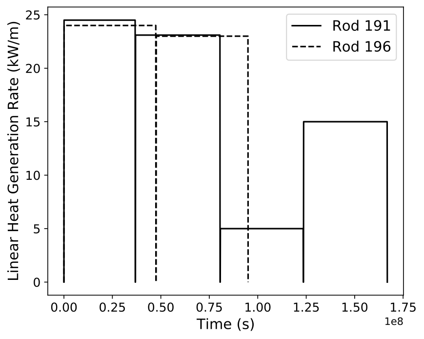
Figure 1: Power history for the commercial base irradiations of Rods 191 and 196.
Figure 2: Maximum cladding temperature applied during the LOCA transient for Rods 191 and 196.
Input files
The BISON input and all supporting files (power histories, axial power profile, etc.) for this case are provided with the code distribution at bison/assessment/LWR/validation/LOCA_Studsvik/analysis.
Material and Behavioral Models
The following material and behavioral models were used for the UO fuel:
UO2Thermal - NFIR: temperature and burnup dependent thermal properties
ComputeFiniteStrainElasticStress and UO2ElasticityTensor: elastic mechanical behavior
UO2RelocationEigenstrain: relocation strains, relocation activation threshold power set to 5 kW/m
ComputeThermalExpansionEigenstrain: thermal expansion with a constant instantaneous thermal expansion coefficient
UO2VolumetricSwellingEigenstrain: MATPRO models for fuel solid swelling and densification.
UO2Sifgrs: fission gas release model used with the combined gaseous swelling model UO2VolumetricSwellingEigenstrain (Pastore et al., 2015)
UO2Pulverization: determines if fuel pulverization occurs for a given burnup and temperature
The following models were used for the Zircaloy-4 cladding that allow for representing ballooning and burst under LOCA conditions:
ZryThermal: temperature dependent thermal properties
ZryCreepLOCAUpdate: High-temperature creep model based on the correlations from (Neitzel and Rosinger, 1980) (Erbacher et al., 1982). This allows for outward creep deformation of the cladding tube under the effect of internal pressurization and high temperature leading to cladding ballooning. The model accounts for the effect of crystallographic phase transition.
ZryElasticityTensor: elastic properties of the cladding
ZryThermalExpansionMATPROEigenstrain: thermal expansion of Zircaloy with the MATPRO model
ZryIrradiationGrowthEigenstrain: ESCORE model volumetric swelling due to irradiation exposure
ZryOxidation: High-temperature cladding oxidation calculated using the correlations of Leistikow (Leistikow et al., 1983)
ZrPhase: Crystallographic phase transition computes the volume fraction of phase for Zr-based cladding materials as a function of time and temperature. The model is based on (Massih, 2009) (Massih and Jernkvist, 2009).
ZryCladdingFailure: evaluates the onset of cladding burst due to combined overstress and plastic instability (Erbacher et al., 1982) (Marcello et al., 2014), and takes into account the effect of Zirconium phase transition and oxidation. The plastic instability and overstrain criteria was chosen for this study as the overstress criterion has been found to severely under-predict burst time on pre-irradiated rods due to the severe initial oxide formation.
Details and references for all of these models listed above can be found on the linked BISON documentation pages.
Additional models
Layered, one-dimensional setups of Studsvik 191 and 196 rods, with the same models listed above, are also available as assessment cases. These models include fuel axial relocation and friction.
Results
The BISON simulation covers all of the phases of the rodlets life including the base irradiation and the entire furnace transient, including post cladding rupture. Results for fuel dispersal are presented. In these studies it is assumed that the total volume of fuel that has exceeded the pulverization threshold (see UO2Pulverization) is assumed to have dispersed.
Table 2 provides a comparison between the BISON simulations and experimental measurements for the total amount of fuel released during the LOCA. It can be seen that BISON does predict that Rod 191 will finely fragment and Rod 196 will not. However, the amount of finely fragmented fuel predicted is much lower in the BISON analysis. This is likely due to the base irradiation power history provided for Rod 191, which results in a calculated average burnup of 67 MWd/kgU when the measured burnup at discharge was 71 MWd/kgU. These differences in burnup can greatly influence the predictions because the pulverization threshold is directly a function of burnup and the threshold is closer to the discharge value than the calculated value.
Table 2: Fuel mass released during the LOCA.
| BISON Rod 191 | Exp. Rod 191 | BISON Rod 196 | Exp. Rod 196 | |
|---|---|---|---|---|
| Mass Released (g) | 18.6 | 41 | 0 | 0 |
References
- F. J. Erbacher, H. J. Neitzel, H. Rosinger, H. Schmidt, and K. Wiehr.
Burst criterion of Zircaloy fuel claddings in a loss-of-coolant accident.
In Zirconium in the Nuclear Industry, Fifth Conference, ASTM STP 754, D.G. Franklin Ed., 271–283. American Society for Testing and Materials, 1982.[BibTeX]
- M. Flanagan and P. Askeljung.
Observations of fuel fragmentation, mobility and release in integral high-burnup, fueled loca tests.
In Enlarged Halden Program Group Meeting 2011. 2011.[BibTeX]
- M. Helin and J. Flygare.
NRC LOCA tests at Studsvik, design and construction of test train device and tests with unirradiated cladding material.
Technical Report STUDSVIK/N-11/130, Studsvik, 2012.[BibTeX]
- S. Leistikow, G. Schanz, H. v. Berg, and A.E. Aly.
Comprehensive presentation of extended Zircaloy-4/steam oxidation results 600-1600 C.
In CSNI/IAEA specialists meeting on water reactor fuel safety and fission product release in off-normal and accident conditions. Riso Nat. Lab., Denmark, 1983.[BibTeX]
- V. Di Marcello, A. Schubert, J. van de Laar, and P. Van Uffelen.
The TRANSURANUS mechanical model for large strain analysis.
Nuclear Engineering and Design, 276:19–29, 2014.[BibTeX]
- A.R. Massih.
Transformation kinetics of zirconium alloys under non-isothermal conditions.
Journal of Nuclear Materials, 384:330–335, 2009.[BibTeX]
- Ali R Massih and Lars Olof Jernkvist.
Transformation kinetics of alloys under non-isothermal conditions.
Modelling and Simulation in Materials Science and Engineering, 17(5):055002, 2009.[BibTeX]
- H. J. Neitzel and H. Rosinger.
The development of a burst criterion for zircaloy fuel cladding under loca conditions.
Technical Report KfK 4343, Kernforschungszentrum Karlsruhe GmbH (Germany, Kernforschungszentrum Karlsruhe, Germany, 1980.[BibTeX]
- G. Pastore, L.P. Swiler, J.D. Hales, S.R. Novascone, D.M. Perez, B.W. Spencer, L. Luzzi, P. Van Uffelen, and R.L. Williamson.
Uncertainty and sensitivity analysis of fission gas behavior in engineering-scale fuel modeling.
Journal of Nuclear Materials, 465:398–408, 2015.[BibTeX]