LOCA IFA-650.4
Overview
The Instrumented Fuel Assembly (IFA)-650.4 experiment completed at the Halden reactor in Norway is part of a series of integral in-pile tests to investigate fuel behavior under simulated LOCA conditions. This test was the fourth in the series and performed on a segment of a rod pre-irradiated in a commercial reactor to an average burnup of 92 MWd/kgU. This high average burnup in the fuel prior to the experiment resulted in significant axial relocation of the fuel during the transient. Cladding failure occurred at 336 seconds after blowdown.
Description of the experiment
The fabrication characteristics of the IFA-650.4 fuel rod are reported in Table 1. The test rod was a segment from the commercially irradiated PWR mother rod. The fuel and cladding materials are UO and duplex cladding (Zry-4 base material with additional alloying elements for improved oxidation resistance) with typical PWR design specifications. The refabricated rod was filled with a gas mixture of 95% argon and 5% helium at 4 MPa. Argon was chosen to simulate the (low-conductivity) fission gases. The rod plenum volume (free gas volume) was made relatively large in order to maintain stable pressure conditions until cladding burst occurred. The total free gas volume (21.5 cm) was thus practically all located in the plenum, outside the heated region.
Table 1: Design data of IFA-650.4 fuel rod (Kekkonen, 2007)
| Fuel material | UO | |
| Fuel density | 95.2 | %TD |
| U enrichment | 3.5 | wt% |
| Active fuel length | 480 | mm |
| Pellet OD | 9.13 | mm |
| Pellet ID | 0 | mm |
| Pellet length | 11.0 | mm |
| Cladding material | SRA Duplex (Zry-4 based) | |
| Cladding Thickness | 0.725 (including 0.1 mm liner) | mm |
| Cladding OD | 10.75 | mm |
| Diametral gap | 170 | m |
| Free volume | 21.5 | cm |
| Fill gas | Ar (95%), He (5%) (after refabrication) | |
| Fill gas pressure | 4.0 (after refabrication) | MPa |
The fuel rod was located in a standard high-pressure flask in the IFA-650 test rig, which was connected to a high-pressure heavy water loop and a blowdown system. The rod was located in the center of the test rig and surrounded by an electrical heater inside the flask. The heater is part of a flow separator, which divides the space into a central channel surrounding the fuel rod and an outer annulus. The heater is used for simulating heat from the adjacent fuel rods in a power reactor core. Cladding temperature is influenced by both rod and heater powers. Two cladding surface thermocouples, TCC1 and TCC2, were located 8.0 cm below the top of the fuel stack, one, TCC3 was located 19 cm above the pellet stack In IFA-650.4 the temperature of the heater was measured by two embedded thermocouples, TCH1 10.0 cm below the fuel top, and TCH2 located 3.5 cm below the fuel mid plane.
The experimental procedure for the IFA-650.4 test is detailed below (Kekkonen, 2007). The LOCA test refers to the experiment performed in the Halden reactor on the pre-irradiated, refabricated PWR fuel rod.
The general test scheme of IFA-650.4 consisted of the following phases:
Preparatory phases. The test started with a steady state irradiation with water cooling. This consisted of a forced circulation phase followed by a natural circulation phase. The forced circulation phase started with steady state operation at a linear heat generation rate (LHGR) of 84 W/cm, with the outer loop connected and the pressure in the loop set to 70 bar. Then the LHGR was decreased to 10 W/cm by decreasing the reactor power. After reaching the correct fuel power level the electrical heater was turned on to the preset value 15 W/cm. The power levels were chosen based on the previous test runs and pre-calculations to achieve the target peak cladding temperature (PCT) of 1073 K during the heat-up phase of the test. Then the flow regime was switched to natural circulation by disconnecting the rig from the outer loop. Full pressure still existed in the rig. Temperatures in the rig were left to stabilize for a few minutes before blowdown.
Blowdown phase. Valves to the dump tank were opened. The channel pressure decreased rapidly to 3–4 bar.
Heat-up phase. Stagnant superheated steam surrounding the test rod provided inadequate cooling and the fuel cladding temperature increased quickly. Ballooning and burst occurred during the heat-up phase and were detected from pressure and temperature signals, 336 s after blowdown. The test was ended by a reactor scram 617 s after the blowdown was initiated.
Model Description
The fuel axial relocation model implemented in BISON utilizes an algorithm that was originally built around FRAPTRAN-1.5 requiring distinct layers to keep track of the mass movement. Therefore, a layered 1D (1.5D) model of the IFA-650.4 fuel rodlet was constructed. In a layered 1D analysis each layer is a 1D generalized plane strain axisymmetric simulation. Thermo-mechanics is solved on each layer individual and global parameters such as fission gas release, internal gas volume and plenum pressure are communicated to the layers. Details of the layered 1D formulation can be found in a previous CASL report (Pitts et al., 2017).
The geometric parameters specified in Table 1 were used to develop the finite-element mesh that suitably represents the experimental rod. Because BISON does not have material properties for the liner the cladding was modeled as Zircaloy-4 for the entire thickness. The fuel was meshed with 30 layers with 11 EDGE2 elements each layer. The cladding was meshed with 31 layers with 30 corresponding with the fuel layers and 1 to represent the plenum. Five EDGE2 elements were used in the radial direction through the cladding thickness. Since the entire rig was not modeled the plenum length was adjusted to result in the same initial free volume (21.5 cm) reported in the refabrication data provided in Table 1. Refabrication in BISON is accounted for by specifying the refabrication temperature, pressure, and volume to suitably reset the rod conditions at the time of refabrication.
Input files
The BISON input and all supporting files (power histories, axial power profile, etc.) for this case are provided with the code distribution at bison/assessment/LWR/validation/LOCA_IFA_650/analysis/IFA_650_4.
Material and Behavioral Models
The following material and behavioral models were used for the UO fuel:
UO2Thermal - NFIR: temperature and burnup dependent thermal properties
ComputeFiniteStrainElasticStress and UO2ElasticityTensor: elastic mechanical behavior
UO2RelocationEigenstrain: relocation strains, relocation activation threshold power set to 5 kW/m
UO2AxialRelocationEigenstrain: strain applied to the fuel in layers that have gained more mass to move into point-wise contact
ComputeThermalExpansionEigenstrain: thermal expansion with a constant instantaneous thermal expansion coefficient
UO2VolumetricSwellingEigenstrain: MATPRO models for fuel solid swelling and densification.
UO2Sifgrs: fission gas release model used with the combined gaseous swelling model UO2VolumetricSwellingEigenstrain (Pastore et al., 2015)
UO2Pulverization: determines if fuel pulverization occurs for a given burnup and temperature
The following models were used for the Zircaloy-4 cladding that allow for representing ballooning and burst under LOCA conditions:
ZryThermal: temperature dependent thermal properties
ZryCreepLOCAUpdate: High-temperature creep model based on the correlations from (Neitzel and Rosinger, 1980) (Erbacher et al., 1982). This allows for outward creep deformation of the cladding tube under the effect of internal pressurization and high temperature leading to cladding ballooning. The model accounts for the effect of crystallographic phase transition.
ZryElasticityTensor: elastic properties of the cladding
ZryThermalExpansionMATPROEigenstrain: thermal expansion of Zircaloy with the MATPRO model
ZryIrradiationGrowthEigenstrain: ESCORE model volumetric swelling due to irradiation exposure
ZryOxidation: High-temperature cladding oxidation calculated using the correlations of Leistikow (Leistikow et al., 1983)
ZrPhase: Crystallographic phase transition computes the volume fraction of phase for Zr-based cladding materials as a function of time and temperature. The model is based on (Massih, 2009) (Massih and Jernkvist, 2009).
ZryCladdingFailure: evaluates the onset of cladding burst due to combined overstress and plastic instability (Erbacher et al., 1982) (Marcello et al., 2014), and takes into account the effect of Zirconium phase transition and oxidation. The plastic instability and overstrain criteria were chosen for this study as the overstress criterion has been found to severely under-predict burst time on pre-irradiated rods due to the severe initial oxide formation.
Details and references for all of these models listed above can be found on the linked BISON documentation pages.
Development of time-dependent boundary conditions
As for the time-dependent boundary conditions such as linear power, coolant pressure histories, and thermal boundary conditions at the cladding outer wall, clearly their accurate determination is crucial to the reliability of the experiment simulation. For the Halden LOCA experiments, evaluating the time-dependent boundary conditions is a very significant task given the complexity of the experimental setup and procedure. Determining the thermal boundary conditions at the cladding outer surface requires modeling heat transfer from the cladding to the coolant during the multiple phases of the IFA-650.4 experimental procedure, with each phase being characterized by a specific coolant condition, including forced and natural circulation, and the dry phase with the coolant becoming steam, the heat transfer being degraded and the heat transfer mode gradually switching from convection to radiation.
Commercial base irradiation
The fuel axial relocation model implemented in BISON utilizes an algorithm that was originally built around FRAPTRAN-1.5 requiring distinct layers to keep track of the mass movement. Therefore, a layered 1D (1.5D) model of the IFA-650.4 fuel rodlet was constructed. In a layered 1D analysis each layer is a 1D generalized plane strain axisymmetric simulation. Thermo-mechanics is solved on each layer individual and global parameters such as fission gas release, internal gas volume and plenum pressure are communicated to the layers. Details of the layered 1D formulation can be found in a previous CASL report (Pitts et al., 2017).
The geometric parameters specified in Table 1 were used to develop the finite-element mesh that suitably represents the experimental rod. Because BISON does not have material properties for the liner the cladding was modeled as Zircaloy-4 for the entire thickness. The fuel was meshed with 30 layers with 11 EDGE2 elements each layer. The cladding was meshed with 31 layers with 30 corresponding with the fuel layers and 1 to represent the plenum. Five EDGE2 elements were used in the radial direction through the cladding thickness. Since the entire rig was not modeled the plenum length was adjusted to result in the same initial free volume (21.5 cm) reported in the refabrication data provided in Table 1.
The IFA-650.4 experiment was carried out using a segment of a PWR rod that had been irradiated in a commercial PWR up to a burn-up of 89.9 MWd/kgU. Given the different thermal-hydraulic boundary conditions between the base irradiation and the subsequent LOCA test two BISON inputs were used to simulation the life of the rodlet. For simplicity, the base irradiation was simulated on the geometry of the refabricated IFA-650.4 rod rather than on the geometry of the original commercial mother rod. The power history for the base irradiation was made available by the Halden Reactor Project in tabulated form and is plotted in Figure 1. During the base irradiation typical PWR parameters were adopted for the coolant conditions (i.e., water at a pressure of 15.3 MPa, an inlet temperature of 580 K and an inlet mass flux of 3800 kg/m-s) The heat transfer from the cladding to the coolant was modeled using BISON's internal coolant channel model for convective heat transfer under PWR conditions.
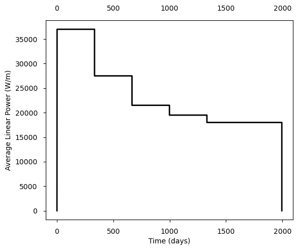
Figure 1: Power history for the commercial base irradiation of IFA-650.4.
As outlined earlier, the Halden test began with preparatory phases of fuel rod irradiation under coolant conditions of forced circulation followed by natural circulation. To determine the temperature boundary conditions at the cladding outer surface, rather than explicitly modeling the cladding-to-coolant heat transfer during these preparatory phases, a pragmatic approach was chosen in which the measured temperatures available from the Halden data were from the thermocouples and inlet and outlet. This approach guarantees good accuracy as the temperature values are derived directly from the measurements. This approach is deemed acceptable because the preparatory phases provide conditioning of the rod for the subsequent LOCA. For the post-blowdown phases, a more detailed approach is used. Since radiative heat transfer to structural components surrounding the rod becomes dominant during the heat-up phase (while it is negligible for fuel performance simulations under normal reactor conditions) a model that accounts for both convective heat transfer stream and this radiative heat transfer is required.
Switching between different approaches to prescribing the thermal boundary conditions (i.e., convection calculations for the base irradiation, prescribed temperatures during the preparatory phases, and convection-radiation calculations during the post-blowdown phases) is accomplished by the MOOSE capability called Controls. During the preparatory and LOCA phases the linear power, coolant pressure, and heater temperatures obtained from the Halden data were applied to the rodlet.
Results
The BISON simulation covers all of the phases of the rodlets life including the base irradiation, preparatory, blowdown, and heat up until the point of failure of the cladding. Results for fuel relocation (mass fraction), cladding profilometry, and rod internal pressure are presented. According to Di Marcello et al. (Marcello et al., 2014) the failure criterion to be used during large strain analyses such as the one analyzed is not unique given the large amount of uncertainty in the experimental conditions. For pre-irradiated rods it is recommended to use the overstrain criteria for Zircaloy failure (See ZryCladdingFailure). In the overstrain criterion the cladding is said to have failed when the average permanent tangential (hoop) strain (i.e., from creep) exceeds an engineering strain value of 40% or a true strain (as used in BISON) of 33.6%. The plastic instability (strain rate) criterion (See ZryCladdingFailure) is included for comparison.
Fuel Relocation
As the cladding balloons during the blowdown and heat-up phases the highly fragmented fuel (due to irradiation to high burnup in the commercial reactor) may be permitted to relocated from upper portions of the rodlet into the ballooned region(s). As the mass relocates the effective diameter of the fuel in the model should be moved radially outward to simulate point-wise contact with cladding and for thermal feedback purposes. The predicted time to burst by BISON using the overstrain criterion was 318.2 and 316.9 s for the plastic instability criterion. The measured value was 336 s.
Figure 2 shows the mass fraction of fuel as a function of axial position at the end of the simulation compared to a gamma scan completed after the experiment but prior to PIE. The BISON simulations indicate that mass accumulates in the midplane region of the rodlet which coincides with the increased gamma scan reading at that location.

Figure 2: Fuel mass fraction as a function of axial position in the rodlet at the time of rupture compared to a gamma scan that took place after the experiment (Kekkonen, 2007).
Cladding ballooning and burst behavior
Figure 3 shows the axial profile of the cladding diameter at the end of the simulation. As expected the cladding profilometry follows a similar trend as the mass fraction because the fuel movement is directly a function of the cladding distention. Therefore, at the location of the largest mass fraction is also the location of the largest cladding diameter predictions.

Figure 3: Calculated cladding outer diameter profile for IFA-650.4 at the end of the simulation compared to the PIE experimental data for the 90/270 degree orientation.
Rod inner pressure evolution
In Figure 4, the time evolution of rod inner pressure during the post-blowdown phases of the IFA-650.4 experiment is compared to the experimental (pressure transducer) data from Halden. A slight over-prediction of the rod pressure during the early portion of the heat-up phase is observed followed by an underprediction in the later portion.

Figure 4: Rod inner pressure evolution during the post-blowdown phase of IFA-650.4 and time to cladding burst. BISON results are compared to the Halden experimental data.
References
- F. J. Erbacher, H. J. Neitzel, H. Rosinger, H. Schmidt, and K. Wiehr.
Burst criterion of Zircaloy fuel claddings in a loss-of-coolant accident.
In Zirconium in the Nuclear Industry, Fifth Conference, ASTM STP 754, D.G. Franklin Ed., 271–283. American Society for Testing and Materials, 1982.[BibTeX]
- L. Kekkonen.
LOCA Testing at Halden; The Fourth Experiment IFA-650.4.
Technical Report HWR-838, OECD Halden Reactor Project, 2007.[BibTeX]
- S. Leistikow, G. Schanz, H. v. Berg, and A.E. Aly.
Comprehensive presentation of extended Zircaloy-4/steam oxidation results 600-1600 C.
In CSNI/IAEA specialists meeting on water reactor fuel safety and fission product release in off-normal and accident conditions. Riso Nat. Lab., Denmark, 1983.[BibTeX]
- V. Di Marcello, A. Schubert, J. van de Laar, and P. Van Uffelen.
The TRANSURANUS mechanical model for large strain analysis.
Nuclear Engineering and Design, 276:19–29, 2014.[BibTeX]
- A.R. Massih.
Transformation kinetics of zirconium alloys under non-isothermal conditions.
Journal of Nuclear Materials, 384:330–335, 2009.[BibTeX]
- Ali R Massih and Lars Olof Jernkvist.
Transformation kinetics of alloys under non-isothermal conditions.
Modelling and Simulation in Materials Science and Engineering, 17(5):055002, 2009.[BibTeX]
- H. J. Neitzel and H. Rosinger.
The development of a burst criterion for zircaloy fuel cladding under loca conditions.
Technical Report KfK 4343, Kernforschungszentrum Karlsruhe GmbH (Germany, Kernforschungszentrum Karlsruhe, Germany, 1980.[BibTeX]
- G. Pastore, L.P. Swiler, J.D. Hales, S.R. Novascone, D.M. Perez, B.W. Spencer, L. Luzzi, P. Van Uffelen, and R.L. Williamson.
Uncertainty and sensitivity analysis of fission gas behavior in engineering-scale fuel modeling.
Journal of Nuclear Materials, 465:398–408, 2015.[BibTeX]
- S. A. Pitts, S. R. Novascone, H. Chen, B. W. Spencer, S. Satpathy, R. J. Gardner, and J. D. Hales.
Verify and validate 1.5D capability.
Technical Report CASL-U-2017-1380-000, Idaho National Laboratory, June 2017.[BibTeX]