Coolant Channel
Sets up the Boundary Conditions, Material, and UserObject classes required to calculate the transfer of heat away from the fuel rod through the coolant channel.
Description
In the operating conditions of Light Water Reactors, fuel rods are surrounded by flowing water coolant: the flowing coolant carries the thermal energy generated from nuclear fission reaction and transfers the heat into a steam generator or drives a turbine directly. To predict the thermal response of a fuel rod, the thermal hydraulic condition of the surrounding coolant needs to be determined. The CoolantChannel action is used to calculate the energy transport of the coolant within BISON through a single coolant channel model. This single channel is used mathematically to describe the thermal boundary condition for modeling the fuel rod behavior. This model covers two theoretical aspects, i.e., the local heat transfer from cladding wall into the coolant and the thermal energy deposition in the coolant in steady state and slow operating transient conditions.
The CoolantChannel action simplifies the input file by creating the classes required to capture the effect of the coolant on the heat transfer at the exterior cladding surface. These created classes model the thermal hydraulics condition surrounding a single fuel rod to provide a thermal boundary condition for use in the analysis of nuclear fuel behavior. Energy conservation is used to derive the coolant enthalpy rise. Applicable heat transfer correlations are used to model the boiling curve prior to departure from nucleate boiling.
Coolant Channel Model Overview
There are no applicable standards on the coolant channel model used in a fuel performance code. It should be recognized that one should refer to a thermal-hydraulics code for detailed modeling of a coolant channel. For the application of a coolant channel model into a fuel performance code, significant emphasis is placed on the energy deposition and the heat transfer characteristics. Assumptions about the flow distribution in the axial and radial directions are made to increase the computational efficiency of the model and are discussed below.
Figure 1 shows the schematic of the coolant channel model. No finite element mesh was assigned to the coolant channel. The meshing of the one dimensional flow channel consists of several control volume with constant flow area A. Inlet pressure, coolant temperature (or enthalpy), and mass flux as a function of time are required input, and they can provide the boundary conditions in solving one-dimensional momentum and energy equations. Heat input into the coolant consists of cladding outer surface heat flux and energy deposits due to interactions of neutrons and gamma rays with coolant water.
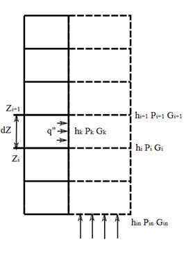
Figure 1: Schematic of one-dimensional coolant channel with upward flow
Figure 2 shows a typical sub-channel at assembly interior for a square lattice in thermal-hydraulics analysis. As can be seen, each channel is bounded by four fuel rods and each fuel rod shares a quarter of its cladding outer surface with the coolant channel. For a fuel performance code, the coolant channel takes the same geometry shown in Figure 2; however, it should be noted that the heat flux from the bounding fuel rod surfaces for the coolant sub-channel all come from the single fuel pin in the analysis to compute the coolant enthalpy for the sub-channel.
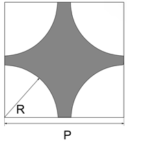
Figure 2: Geometry of an interior sub-channel channel, bounded by four separate fuel rods
Governing Equations
The mathematical single channel model is developed from one-component, one-dimensional, and two-phase compressible flow. With a set of assumptions, these equations are integrated over a control volume to develop a set of working equations. This model was derived with an emphasis on the heat transfer characteristics between the cladding and coolant water.
The conservation of mass is given by (1) where is the density of the mixture of the steam and liquid and is the void fraction of the steam. is the mass flux of the mixture of the steam and liquid in the unit of .
Recall the conservation of momentum equation, (2) with the density of the coolant mix given as (3) where x is the vapor quality, A is the flow area, is the friction factor, and is the perimeter of the flow channel.
The energy balance equation is given by: (4) where
(5) (6)
A few assumptions are applied to simplify the model:
Coolant channel has a constant flow area
Pressure drop analysis is neglected and coolant pressure at any axial location is inlet pressure
Flow is homogeneous and no slip between the liquid phase and the steam, then the void fraction is related to vapor quality by: (9) Subsituting Eq. (9) into Eq. (3) and Eq. (5), we obtain and
Pressure is allowed to vary in time; however, the work done by the pressure on the coolant is neglected.
With above assumptions, the momentum equation is not needed in the analysis and the governing equations can be reduced to the conservation of mass, Eq. (1), and a simplified energy balance, from Eq. (4). (7) (8)
Coolant Channel Model Limitations
Assumptions and limitations of the coolant channel model are summarized below:
Closed channel: The lateral energy, mass, and momentum transfer in the coolant channel within a fuel assembly is neglected. Therefore, the momentum, mass continuity, and the energy equations are only considered in one-dimension, i.e., the axial direction.
Homogeneous and equilibrium flow: For the flow involving both the vapor and liquid phases, the thermal energy transport and relative motions between the two phases are neglected. This essentially assumes the two-phase flow is in a form of one pseudo fluid.
Fully developed flow: In the application of most heat transfer correlations, the entrance effects are neglected. The heat transfer is assumed to happen in a condition that the boundary layer has grown to occupy the entire flow area, and the radial velocity and temperature profiles are well established.
Pressure drop neglected: The pressure drop due to flow induced resistance is not accounted for in the coolant channel model. Instead, coolant pressure as a function of time and axial location can be an input provided by user through a hand calculation or using a computer code.
Constructed Objects
Table 1: Correspondence Among Action Functionality and Moose/BISON Objects for the CoolantChannel Action
| Functionality | Replaced Classes | Associated Parameters |
|---|---|---|
| Calculate the convective heat transfer from the cladding to the coolant | ConvectiveHeatFluxBC | boundary: the mesh sideset on which the coolant channel calculation will be run, usually the outer cladding surface |
variable: the temperature variable | ||
| Calculate the heat transfer properties of the coolant fluid | CoolantChannelMaterial | inlet_quality, inlet_temperature, inlet_pressure, and inlet_massflux: coolant fluid properties at the inlet |
coupledEnthalpy: the variable containing the coolant system enthalpy | ||
heat_transfer_coefficient, heat_flux heat_transfer_mode, htc_correlation_type, and chf_correlation_type: heat transfer material properties | ||
rod_diameter and rod_pitch: dimensions associated with the fuel pellets | ||
linear_heat_rate and axial_power_profile: parameters associated with power generation from the fuel rod | ||
variable: the temperature variable | ||
| Set the coolant material property database | IAPWS95HEMFluidProperties if water (default), or SodiumProperties if sodium | coolant_material: the type of coolant fluid material |
| Calculate the total heat flux from the complete fuel rod length | PartialSumHeatFluxIntegral | number_axial_zone: the number of zones into which the integration of the heat flux is separated |
| Calculate the entropy with a user object | CoolantChannelUserObject | num_layers: number of radial zones |
The presence of some input parameters causes others to be ignored. The following parameters are given precedence over settings in the input file:
Heat Transfer Coefficients: If
heat_transfer_coefficientis given, its value will be assigned to the given boundary. All other parameters related to the heat transfer coefficient calculation are ignored.Enthalpy: If
coupledEnthalpyis present, the value of that parameter will be used for enthalpy.Heat Flux Calculation: If
coupledEnthalpyis not specified in the input file, the heat flux is calculated based onlinear_heat_rate, specification ofnumber_axial_zone, and specification ofheat_flux, in highest precedence order. The integrated heat flux is computed based on the same precedence. As an example, ifnumber_axial_zoneandheat_fluxare specified,heat_fluxwill be ignored.
These parameters are used as inputs to the heat transfer coefficient correlations.
Example Input Syntax
An example of the CoolantChannel action block is given below, where the auxkernel, materials, and userobjects are automatically created to model the heat transfer from the cladding boundary to the coolant channel:
[CoolantChannel<<<{"href": "index.html"}>>>]
  [clad_outer_surface]
    boundary<<<{"description": "The boundary where the coolant channel calculation will run"}>>> = 3
    variable<<<{"description": "The name of the variable representing temperature"}>>> = temp
    inlet_temperature<<<{"description": "Inlet temperature in K "}>>> = 559 # K
    inlet_pressure<<<{"description": "Inlet pressure in Pa"}>>> = 15.5E6 # Pa
    inlet_massflux<<<{"description": "Inlet mass flux in kg/m^2-sec"}>>> = 3886 # kg/m^2-sec
    rod_diameter<<<{"description": "Rod diameter in meter"}>>> = 0.95e-2 # m
    rod_pitch<<<{"description": "Rod pitch in meter"}>>> = 1.26e-2 # m
    linear_heat_rate<<<{"description": "Linear heat generation rate in W/m"}>>> = linear_heat_rate
    axial_power_profile<<<{"description": "Axial power profile"}>>> = axial_power_profile
    heat_transfer_mode<<<{"description": "heat transfer mode"}>>> = 2 # D-B correlation
  []
[]Available Actions
- Bison App
- CoolantChannelActionSets up the Boundary Conditions, Material, and UserObject classes required to calculate the transfer of heat away from the fuel rod through the coolant channel.