Whole Pin Furnace Experiments
The Whole Pin Furnace (WPF) assessment case simulates a series of out-of-pile transient experiments performance in the WPF facility at Argonne's Alpha-Gamma Hot Cell Facility (AGHCF) (Tomchik, 2021).
Overview
As FBTA facility could only handle a small segment of the sectioned irradiated fuel pins, and it was only capable of investigation of fundamental and localized fuel behaviors during transient events. However, as a whole fuel pin is a complex system that contains components beyond fuel and cladding, which includes filled sodium, initially filled gas, and released fission gas in plenum, etc., whole-pin out-of-pile transient tests are essential to capture these complex and comprehensive phenomena that involve contributions from different components. The WPF was established to perform transient testing for the entire fuel pin system to get more engineering information of an irradiated pin’s responses to power transients.
Test Description
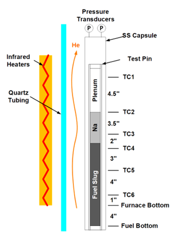
Figure 1: Experiment setup of the Whole Pin Furnace (WPF) FM-1 Experiment.
The WPF system was designed to perform two types of tests, (1) run-to-breach tests, and (2) safety demonstration tests. Those run-to-breach tests involve heating an intact in-pile-irradiated fuel pin at a high temperature (e.g. 800 °C) expected in accident scenarios and holding the temperature until the cladding failure. The safety demonstration tests, on the other hand, were designed to prove that certain fuel designs can survive some specific transient events. The design of the WPF system is shown in Figure 1. A metallic fuel pin that was irradiated in a fast neutron reactor (e.g. EBR-II) is entirely encapsulated in a stainless steel tube. Six K-type thermocouples are also installed inside the stainless steel tube to monitor the temperatures at different axial positions. Outside the stainless steel tube, an S-type thermocouple is attached on the tube to control the heating of the fuel pin. On the top of the stainless steel tube, two pressure transducers are installed to monitor the breach of cladding by detecting pressure increase caused by the released plenum gas. The entire stainless steel capsule tube is located in a quartz tube with He coolant flowing inside. The quartz tube is heated in a 65 cm long heating chamber powered by four longitude infrared filament lamps. The furnace is capable of operating at 1100 °C for extended periods or 1650 °C for short periods at a ramping rate up to 30 °C/s. The furnace has a long heating region with near-uniform power and temperature profile. Additionally, the released plenum gas is also analyzed by a mass spectroscopy.
During the IFR program, there were seven WPF experiments that were conducted. In the current WPF assessment case, one of the seven WPF experiment, FM-1, is adopted. Some basic parameters of the FM-1 experiment can be found in
Table 1: Specifications of the FM-1 experiment
| Test | Exp/Pin | Fuel | Cladding | P/F Ratio | Burnup (at.%) | Temperature (°C) | WPF Experiment Type |
|---|---|---|---|---|---|---|---|
| FM-1 | X425/T418 | U-10Zr | HT9 | 1.0 | ~3.0 | 820 | Run-to-breach |
BISON-FIPD and BISON-OPTD Integration
To simulate a WPF FM-1 test, two BISON simulations are needed. The first one is a steady state irradiation simulation to obtain the initial fuel and cladding conditions prior to the transient test. The second one is a transient simulation to simulate the out-of-pile heating stage of the WPF test.
For the first stage, the BISON-FIPD integration powered simulation approach, as used in the X447 Assessment Case, is adopted for the X425 T418 pin. For the second stage, as the out-of-pile transient experiment data are maintained in the OPTD database(Tomchik and Oaks, 2020), the simulation is enabled by the BISON-OPTD integration. Both test condition parameters and posttest measurement data from OPTD are used to help establish the simulation model and to evaluate the simulation results.
Model Description

Figure 2: Two-stage simulation approach utilizing checkpoint.
The first stage (i.e., steady state irradiation in EBR-II X425 subassembly) simulation is similar to the setup in the X447 Assessment Case. So the model description here is focused on the second stage (i.e., out-of-pile heating in WPF facility) simulation, including how the data generated at the first stage simulation are used as the initial conditions.
As both stages of simulations involve the same whole fuel pin, which is simulated using a 2D-RZ axisymmetric model. MOOSE's intrinsic Restart and Recover capability (checkpoint data, to be specific) is utilized to enable the switch between the two stages of simulations. The final "frame" of the steady state simulation is loaded through the checkpoint data as the initial condition of the transient data (see Figure 2).
Geometry and Mesh
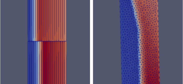
Figure 3: Improvements by using locally refined triangular elements in mesh.
FIPDRodletMeshGenerator is used to generate the 2D-RZ mesh of the whole fuel pin. Due to the severe degradation of the cladding's mechanical properties during the out-of-pile furnace transient testing, the cladding of the pin suffers a series of localized effects including loss of mechanical stress due to eutectic cladding penetration as well as the concentration of stress. Thus, the conventional QUAD elements based structured mesh may lead to artificial effects as shown in the left half of Figure 3. Thus, FIPDRodletMeshGenerator has been updated to allow localized refinement using unstructured mesh consisting of TRI elements. This local refinement is usually used near the top of the fuel column where the most prominent penetration is expected to occur. As shown in the right half of Figure 3, such an approach can significantly relieve the artificial effects caused by the conventional mesh.
Material and Behavioral Models
The majority of the models used in this assessment are similar to those used in X441 and X447 assessment cases. One major unique task of this FM-1 WPF assessment case is to assess the fuel-cladding eutectic melting effect and its effects on other fuel performance phenomena.
ADMetallicFuelLiquidCladdingPenetration: Calculates the liquid penetration rate of UPuZr fuel into HT9 cladding (the ANL improved conservative correlation is adopted).
MetallicFuelMeltingFunction: Converts the axially-dependent fuel melting thickness into a space function that describes the local melting status of the fuel region.
MetallicFuelWastageDegradationFunction: Converts the axially-dependent cladding penetration thickness into a space function that describes the local penetration status of the cladding region.
Out-of-Pile Transient Conditions
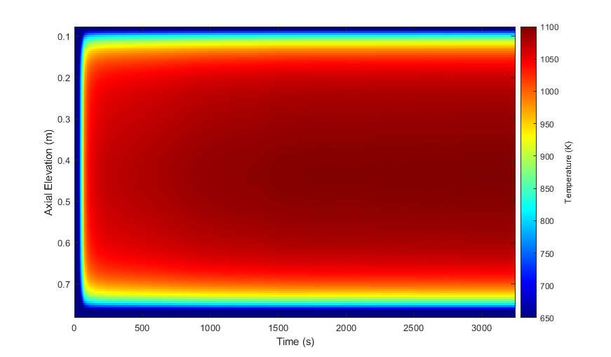
Figure 4: Time-varying temperature profile used for cladding outer surface temperature boundary conditions in FM-1 simulation.
The main condition that is needed for WPF FM-1 simulation is the time evolution of temperature profile in the presence of furnace heating. In this assessment case, the furnace heating is applied using a Dirichlet boundary condition on the outer surface of cladding. The data shown in Figure 4 are used as the boundary condition of the FM-1 test simulation.
This temperature input was derived from the normalized radiant power (NRP) correlation summarized in the FM-1 documentation (ANL-IFR-154),
(1)where is the axial elevation position (in.) from the bottom of the furnace heating area.
Based on the NRP, the axial-dependent temperature (in Kelvin) is calculated using an empirical correlation derived based on the thermal radiation,
(2)As six measurement thermocouples and one control thermocouple are installed, the value can be used to derive the time evolution of the NRP. Since the control thermocouple is located outside the tube, TC4's measurement value was used for the NRP calculation that leads to the temperature profile shown in Figure 4.
Input files
The parametrized input files for the steady state stage 2D-RZ whole fuel pin models are located at bison/assessment/metallic_fuel/WPF/analysis/X425_T418. The corresponding FIPD-based data files for T418 pin are located in the bison/fipd-bison-integration-data/X425/T418 submodule folder. FIPD users may manually download needed data files and modify assessment inputs to use these downloaded files if they do not have the fipd-bison-integration-data submodule setup.
The input files for the out-of-pile transient stage WPF models are located at bison/assessment/metallic_fuel/WPF/analysis/FM-1. The main body of the input files are the same as those for the steady state simulation of X425 T418 pin with some models/conditions switched for the transient simulation.
Results and Discussion
Steady State Simulation Results
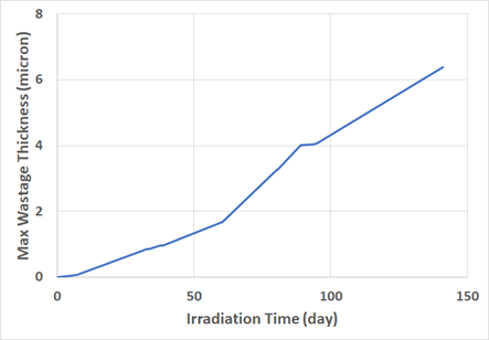
Figure 5: Time evolution of maximum FCCI wastage in the T418 pin during steady state irradiation in X425 as predicted by BISON.
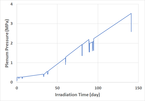
Figure 6: Time evolution of plenum pressure in the T418 pin during steady state irradiation in X425 as predicted by BISON.
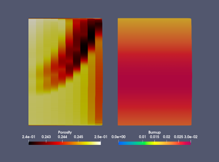
Figure 7: The porosity and burnup in the fuel region of the T418 pin after irradiation in X425
As X425/T418 is a low burnup intermediate temperature experiment, the peak cladding temperature of the pin was only slightly higher than 600 °C while the peaking fuel temperature is approximately 700 °C. Therefore, the FCCI wastage formation during the steady state irradiation is quite benign, which is merely ~6 micron thick as predicted by BISON (see Figure 5). The fission gas release at the end of the irradiation is predicted by BISON to be ~60%, leading to a plenum pressure of approximately 3.5 MPa, as shown in Figure 6. Some initial gas buildup has already been done although the burnup is still relatively low.
As illustrated in Figure 7 is the final porosity and burnup profile of the T418 pin right after the irradiation in the subassembly X425. It is clear that the porosity has already been saturated at ~0.25, which corresponds to 33% gaseous swelling, which is consistent with the metallic fuel’s behavior at ~3 at.% burnup.
Out-of-Pile Transient Simulation Results
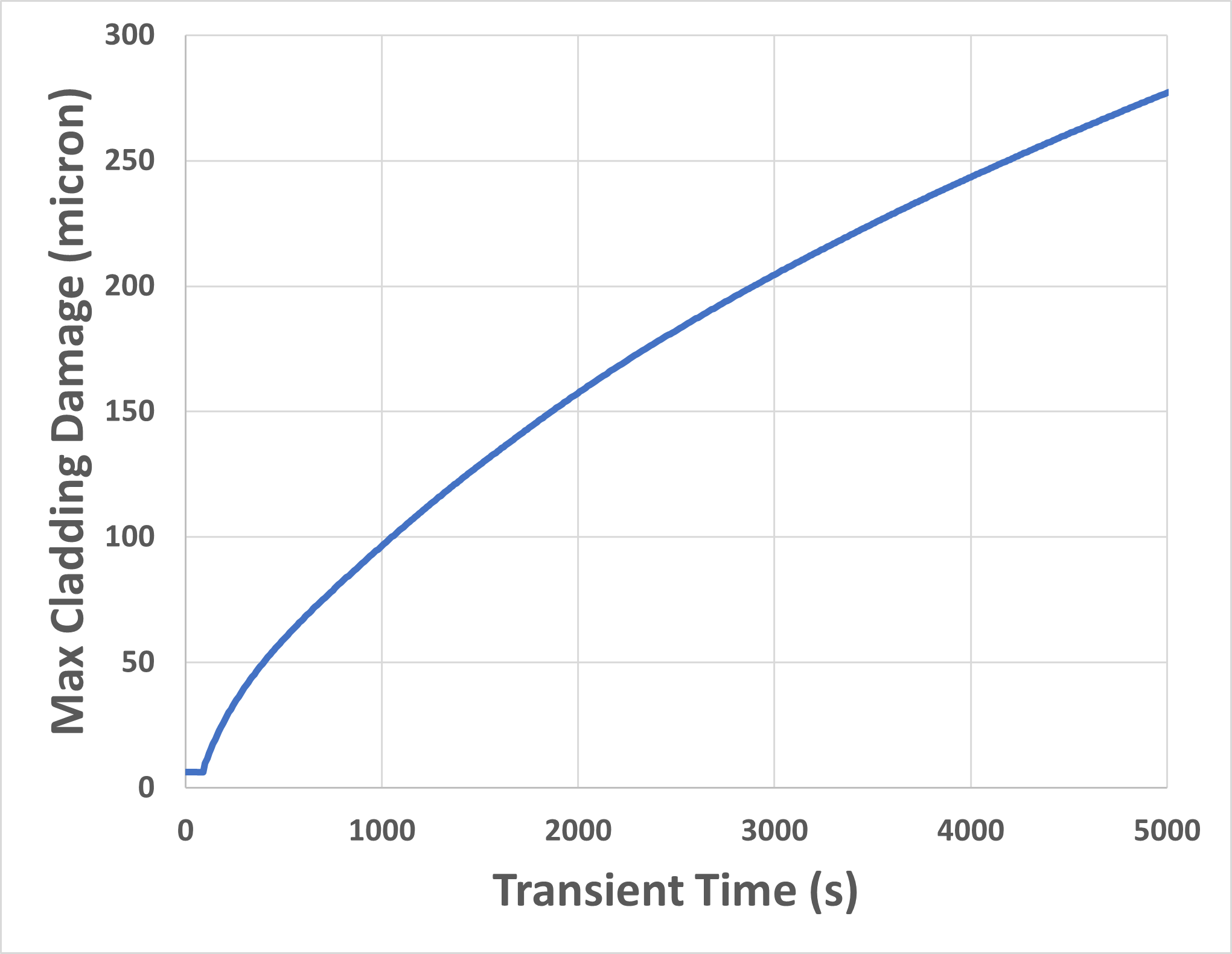
Figure 8: BISON predicted time evolution of the maximum cladding damage (steady state FCCI plus transient liquid cladding penetration) during the FM-1 test.
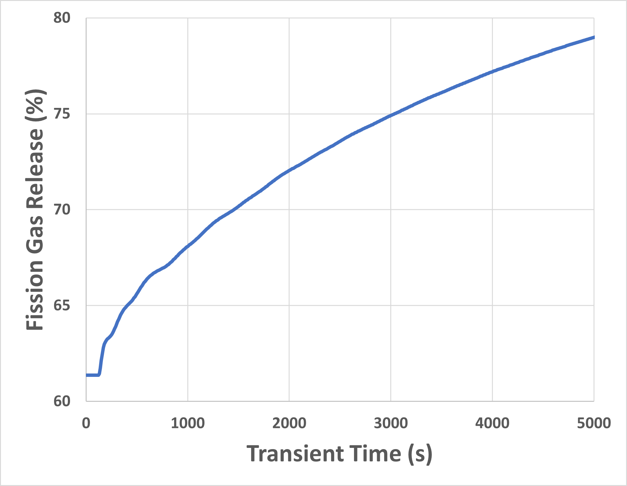
Figure 9: BISON predicted time evolution of the fission gas release mainly due to fuel melting during the FM-1 test.
As the peak temperature reached up to ~820 °C during the FM-1 test, the cladding was subjected to severe liquid penetration due to fuel-cladding eutectic melting. In Figure 8, the maximum cladding damage is illustrated. As the latest improved liquid penetration correlation was adopted, the kinetics shows a clearly parabolic feature. The total cladding damage exceeds 250 microns as the transient time exceeds ~4,000 seconds. Namely, the majority of the original 381-micron-thick cladding has been damaged at this time point, as predicted by BISON, implying the cladding failure event.
On the other hand, the liquid penetration on the cladding side corresponds to the melting on the fuel site. As a simple fuel melting correlation was also implemented here, the fuel melting effects, especially its effect on fission gas release, can be revealed. As shown in Figure 9, mainly because of the fuel melting, the predicted percentage fission gas release increases from ~60% to ~80% during the FM-1 test. This additional gas in the plenum slightly increases the predicted plenum pressure.
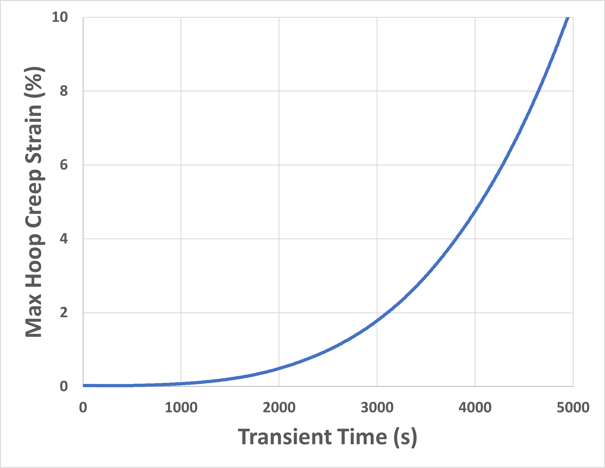
Figure 10: BISON predicted time evolution of the maximum hoop strain cause by cladding creep during the FM-1 test.
Meanwhile, as the effective cladding thickness continues to shrink due to the liquid penetration, the stress in the cladding that is required to maintain the pressure difference between the internal (plenum) and external (testing tube) becomes larger and larger, leading to a prominent creep deformation in the hoop direction. As shown in Figure 10, the BISON predicted maximum creep strain in the hoop direction exceeds ~2% near 3,000 seconds and ~4% near 4,000 seconds. Note that the HT9 creep model implemented in BISON only calculates primary and secondary creep deformation. The tertiary creep deformation, which could contribute to approximately 40% of the creep deformation near the failure event, was not calculated here.
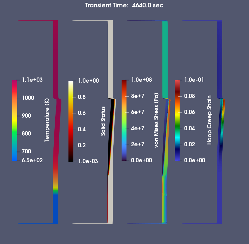
Figure 11: BISON predicted key cladding performance phenomena near the end of the actual FM-1 end time.
Near 4,600 seconds, where the FM-1 test was terminated due to the breach of the cladding, the key BISON predicted fuel performance phenomena parameters are illustrated in Figure 11. At this time, a prominent cladding deformation can be identified, which affects the top half of the fuel region. The deformation is caused by the thinning of the cladding that leads to a ~100 MPa hoop stress in the cladding.
In the FM-1, the cladding breach was found to occur at ~260 mm above the fuel bottom, namely, near the z/L0.75 position. According to Figure 11, although the z/L0.75 position is significantly affected by the liquid cladding penetration and subsequent cladding deformation, the most affected zone is still the top of the fuel (z/L1.0). Meanwhile, at the breach position, the metallograph is provided as the left half of Figure 12. The liquid penetration depth in the cladding shown in Figure 12 is varying in different azimuthal direction, ranging from marginal interaction to breaching. The average penetration depth is around 1/2 of the original cladding thickness, which is comparable to the 2D-RZ BISON simulation results (right half of Figure 12). The metallograph also indicates the melting fuel zone, which is slightly smaller than the BISON prediction. The larger melting zone in BISON could be caused by the fact that the current BISON model does not consider the latent heat of fusion.
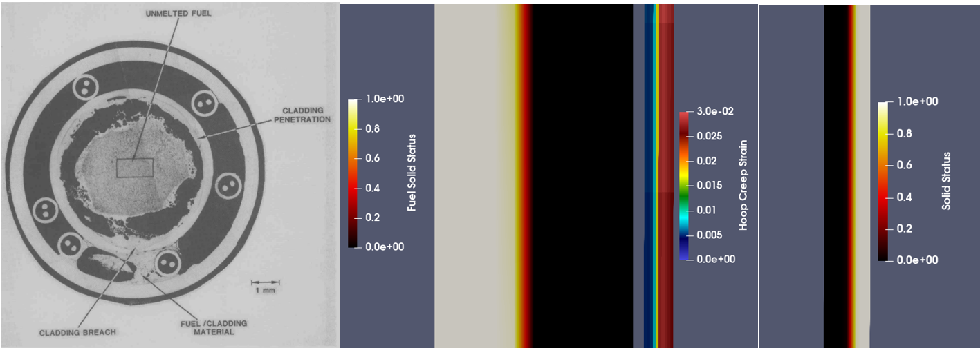
Figure 12: The metallograph of the cladding failure position (260 mm above the fuel column bottom, or z/L0.76) in comparison to the corresponding region in BISON’s simulation (Wright et al., 1991).
References
- Carolyn Tomchik.
Out-of-pile furnace tests on fast reactor metallic fuels conducted at the AGHCF.
Technical Report ANL-ART-217, Argonne National Laboratory, 3 2021.
doi:10.2172/1779724.[BibTeX]
- Carolyn Tomchik and Aaron Oaks.
Status and availability of OPTD, the out-of-pile transient database.
Technical Report ANL-ART-214, Argonne National Laboratory, 9 2020.
doi:10.2172/1690266.[BibTeX]
- A. E. Wright, Y. Y. Liu, J. W. Holland, and T. H. Bauer.
Performance analysis and checkout of the whole pin furnace system.
Technical Report ANL-IFR-154, Argonne National Laboratory, 10 1991.
doi:10.2172/714939.[BibTeX]