EBR-II X447 Experiment
A Metal Fuel Assessment Case Focused on High-Temperature Cladding Failure Evaluation
Overview
The IFR (Integral Fast Reactor) Experiment X447/A was selected to form an assessment case with a focus on the evaluation of the Fuel-Cladding and Coolant-Cladding Chemical Interaction (FCCI/CCCI) induced cladding degradation models for the U-10Zr/HT9 fuel solution. 19 U-10Zr/HT9 pins were irradiated in the X447/A subassembly with two pairs of pins involved in reconstitution between X447 and X447A. Therefore, the 15 U-10Zr/HT9 pins that were irradiated throughout the experiment are the focus in this X447 assessment case. Two BISON model sets were used for X447 in this assessment case. One is the Legacy Model Set that uses non-automatic differentiation models and node/face constraints based contact models. Many details on the development of this assessment case with the legacy model set can be found in Miao et al. (2021). The other is the Enhanced Model Set that features automatic differentiation models and mortar-based contact models.
Test Description
X447/A was designed to test the high-temperature performance of HT9 cladding and its compatibility with binary U-10Zr fuel (Pahl et al., 1993). The experiment utilized MK-D61 inner blanket driver type subassembly hardware. The coolant was orificed in this experiment to intentionally raise peak HT9 cladding temperature beyond 650 C. MK-D61 hardware adopted in X447/A usually contained 61 fuel pins (see Figure 1).
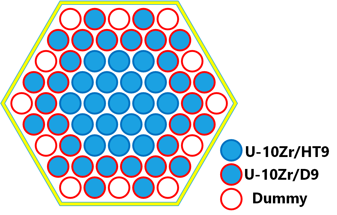
Figure 1: Schematic showing the U-10Zr/HT9 pins locations in X447/A subassembly.
However, as EBR-II enforced a subassembly mean coolant outlet temperature of 544 C, 12 solid dummy fuel pins were included to reduce the subassembly total power. Then 19 HT9 clad and 30 D9 clad U-10Zr fuel pins were irradiated in the subassembly X447 to a burnup around 4.7 at.%. Then four HT9 clad pins were replaced with fresh fuel pins before the irradiation experiment continued as subassembly X447A to achieve an ultimate burnup of approximately 10 at.%. In the IFR X447/A experiment, all the HT9 clad pins were located in the center region of the subassemblies to be exposed to high cladding temperature, while the D9 clad pins were located in the peripheral region along with dummy pins. In the presence of adjacent dummy pins, all the D9 clad pins experienced much lower irradiation temperatures and thus had no issues surviving throughout the experiment. At the end, among the 15 HT9 clad and U-10Zr fueled pins irradiated to approximately 10 at.% burnup, the cladding of two pins (DP70 and DP75) were found to have breached during the steady-state high-temperature irradiation. The cladding failure occurred near the top of the fuel slugs, corresponding to the peak cladding temperature locations. More importantly, severe FCCI wastage formation and prominent CCCI wastage formation were observed in those HT9 clad pins irradiated to ∼10 at.% burnup at elevated temperatures. In some cases, over one-third of the cladding thickness was consumed by FCCI wastage formation. Thus, the HT9 cladding failures observed in X447/A were determined to originate from a combined effect of FCCI wastage-induced cladding degradation and thermally-activated creep rupture caused by internal plenum pressure buildup. The X447/A experiment was a valuable experiment for FCCI/CCCI study because the wastage formation effects were prominent. In general, this experiment was important for HT9 cladding as it defined the operating condition envelope of applying HT9 cladding in sodium-cooled fast reactors (SFRs). Therefore, only the HT9 clad pins in X447/A experiment were investigated in this evaluation effort. In particular, four pins with most PIE data available (i.e., DP04, DP11, DP70, and DP75) are the focus here.
BISON-FIPD Integration
Many crucial fuel performance behaviors are highly sensitive to temperature and irradiation dose history. Hence, high-fidelity irradiation condition data and fuel design parameters are crucial for fuel performance code calibration, verification and validation (V&V). Meanwhile, comprehensive post-irradiation examination (PIE) data collected after the irradiation experiment are key references for assessing fuel performance models. As part of the legacy IFR program, these data about the IFR experiments conducted at EBR-II, including the X447/A experiment, are being recovered and maintained in Argonne National Laboratory’s SFR Fuels Irradiation and Physics Database (FIPD) (Yacout et al., 2021). The quality assurance efforts are on-going to eventually make FIPD data conformant with the requirements of the ASME NQA-1 Standard. To facilitate the use of these data stored in FIPD for BISON metallic fuel model V&V, efforts have been made on both FIPD and BISON sides through the BISON-FIPD integration project. This X447 assessment case is powered by these BISON-FIPD integration accomplishments, and thus is a demonstration case of the integration. The FIPD-based data as well as the related BISON/MOOSE classes used to handle those data are listed in Table 1.
Table 1: Use of BISON-FIPD Integration for X447 Assessment Case
| FIPD-Based Data Type | Related BISON/MOOSE Class | Category of Data |
|---|---|---|
| Fuel Pin Design Data | FIPDRodletMeshGenerator | Pin Design & Geometry |
| Time-Varying Pin-Averaged Power | PiecewiseLinear | Irradiation Conditions |
| Time-Varying Pin-Averaged Fast Neutron Flux | PiecewiseLinear | Irradiation Conditions |
| Power Peaking Factor | FIPDAxialProfileFunction | Irradiation Conditions |
| Fast Neutron Flux Peaking Factor | FIPDAxialProfileFunction | Irradiation Conditions |
| Time-Varying Cladding Outer Surface Temperature | FIPDAxialProfileFunction | Irradiation Conditions |
| Axial-Dependent Cladding Strain | FIPDAxialPIEComparison | Post-Irradiation Examination Data |
While all the FIPD data mentioned in Table 1 are available for downloading as CSV files on the FIPD website, those CSV data files that are needed by the BISON assessment cases are simultaneously maintained in a separate repository called FIPD-BISON Integration Data. This repository is set as an optional submodule of the BISON code. Any users who want to run this X447 assessment case must activate this submodule. All FIPD users can request for the access to this repository.
Pin Design Parameters
All the fuel pin design data of this assessment case are adopted from the FIPD database. As multiple versions of pin design data are available in FIPD, including nominal design description, as-built design specifications, and measured fabrication data. As-built design specifications are used in this assessment case due to their consistence and completeness. For each of the fifteen pins involved in this assessment case, a separate CSV file available in the FIPD-BISON Integration Data is read by BISON's FIPDRodletMeshGenerator to generate the axisymmetric 2D mesh as well as the corresponding MeshMetaData.
Operating Conditions and Irradiation History
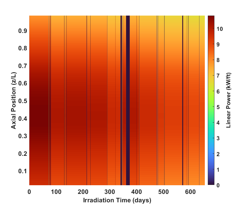
Figure 2: Time and axial dependent power profile for pin DP11.
Calculated pin-by-pin operating conditions data from the FIPD database are used in this assessment case. For each pin, time-varying pin-averaged power and fast neutron flux information are used along with corresponding axial peaking factors to provide complete time and axial dependent irradiation condition profiles (see Figure 2 and Figure 3). Here, the power profile is used as the heat source and then to deduce fuel depletion (burnup) for other models, while the fast neutron flux profile is used to account for irradiation effects especially the irradiation creep of the cladding.
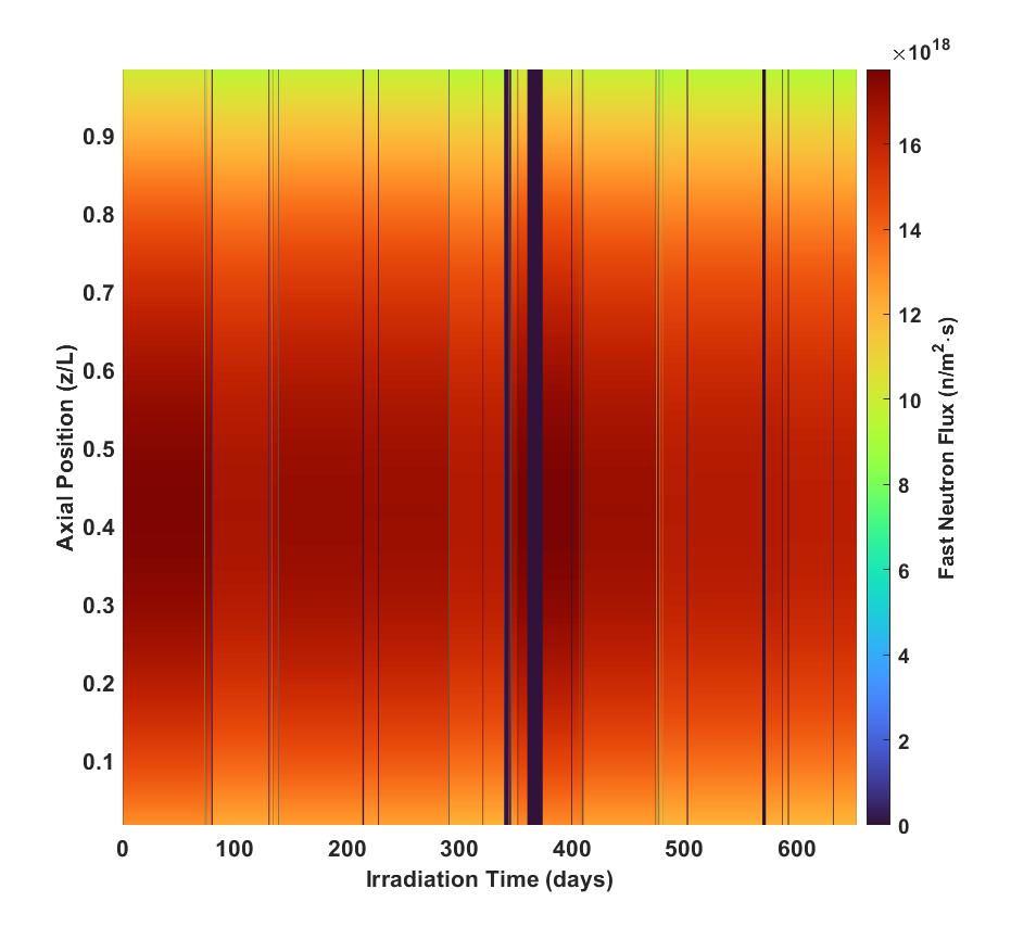
Figure 3: Time and axial dependent fast neutron flux profile for pin DP11.
In the FIPD-BISON Integration Data, both power and fast neutron flux data are provided in the form of two separate CSV files, respectively: a time-dependent average power/flux CSV file in the standard format that can be directly loaded by MOOSE's intrinsic PiecewiseLinear Function class, and a peaking profile CSV file that can be loaded by BISON's dedicated FIPDAxialProfileFunction.
Due to the existence of the dummy pins and pin reconstitution in the experiment X447, BISON's intrinsic coolant channel models (i.e., the generic CoolantChannelAction and the specific SodiumCoolantChannel) might not make best prediction, especially when the neighboring fuel pins have dissimilar power profiles. In that case, time-varying cladding outer surface temperature available in the FIPD database, which is calculated by thermal hydraulics code SuperEnergy2 (Basehore and Todreas, 1980), is used directly as the temperature boundary conditions (see Figure 4 for an example).
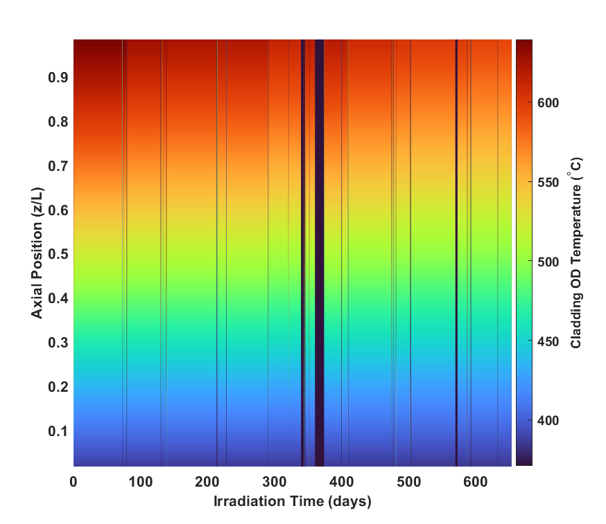
Figure 4: Time and axial dependent outer surface temperature profile for pin DP11.
The time-varying cladding outer surface temperature is provided as a single CSV file for each pin in the FIPD-BISON Integration Data, which can also be read by FIPDAxialProfileFunction.
Post-Irradiation Examinations
The main focus of this assessment case is the consequences of cladding degradation due to the FCCI/CCCI phenomena, which is the deformation and failure of the HT9 cladding. The damage/failure of the cladding is usually quantified by cumulative damage fraction (CDF), which is a statistical and virtual quantity that cannot be directly measured. Therefore, the major experimentally measured data that are valuable here are the deformation profiles of the HT9 cladding. The cladding deformation of the X447 fuel pins were measured by contact profilometry and sometimes also laser profilometry. The digitized data are available in FIPD and used in this assessment case for assess the cladding deformation predicted by BISON.
In the FIPD-BISON Integration Data, the cladding strain profile based on profilometry measurement is provided in a single CSV file for each pin. The data can be loaded by FIPDAxialPIEComparison to be directly compared with the BISON predictions.
Model Description
Geometry and Mesh
The 2D-RZ meshes for the X447 pins are generated with the intrinsic rodlet meshing capability in BISON's FIPDRodletMeshGenerator. The mesh generator directly reads the FIPD-based pin design parameter CSV file and generates the mesh along with a series of MeshMetaData to help ensure consistent use of pin geometry data throughout the simulations. For the enhanced model set, lower-dimensional elements are then added to the fuel and cladding contact surface sidesets with LowerDBlockFromSidesetGenerator. These additional side elements serve as contact surfaces for the Lagrange multiplier variables parameterizing mortar contact.
Material and Behavioral Models
The following material and behavioral models for the UPuZr fuel (note that in the case of X447, all the pins use U-10Zr fuels) were used in these cases. The "AD" prefix denotes that the material properties are computed with Automatic differentiation:
| Legacy Model Set | Enhanced Model Set | Description |
|---|---|---|
UPuZrElasticityTensor | ADUPuZrElasticityTensor | Isotropic elastic mechanical properties |
UPuZrCreepUpdate | ADUPuZrCreepUpdate | Creep mechanical properties and deformation behavior |
UPuZrVolumetricSwellingEigenstrainLM | ADSimpleFissionGasViscoplasticityStressUpdate | Calculates the change in volume due to gaseous fission product production in UPuZr |
UPuZrVolumetricSwellingEigenstrainLM | ADBurnupDependentEigenstrain | Calculates the change in volume due to solid fission product production in UPuZr |
UPuZrFissionRate | ADUPuZrFissionRate | Computes fission rate based on linear power, axial power profile and Pu and Zr concentrations |
UPuZrBurnup | ADUPuZrBurnup | Computes the burnup for UPuZr metallic fuel |
UPuZrThermal | ADUPuZrThermal | Calculates the thermal conductivity and specific heat for UPuZr fuel |
ComputeThermalExpansionEigenstrain | ADUPuZrThermalExpansionEigenstrain | Computes an eigenstrain due to thermal expansion for UPuZr using a function that describes the mean thermal expansion as a function of temperature |
| FgrUPuZrLM | ADSimpleFissionGasViscoplasticityStressUpdate | Fission gas release model for UPuZr metallic fuel (AD: legacy correlation from LIFE-METAL) |
| Neglected; only prominent beyond ~10 at.% bunrup | ADUPuZrHotPressingStressUpdate | Computes the inelastic strain of UPuZr metallic fuel due to hot pressing |
| Neglected | ADUPuZrSodiumLogging | Computes the local fractional amount of sodium logging |
The following material and behavioral models for the HT9 cladding were used in these cases:
| Legacy Model Set | Enhanced Model Set | Description |
|---|---|---|
HT9ElasticityTensor | ADHT9ElasticityTensor | Elastic mechanical properties |
HT9CreepUpdate | ADHT9CreepUpdate | Creep mechanical properties and deformation behavior |
| Neglected | Neglected | Volumetric Swelling of HT9 is neglected. As a tempered martensitic steel, HT9 does not swell as prominent as its austenitic stainless steel counterparts (316SS and D9). |
ComputeThermalExpansionEigenstrain | ADComputeThermalExpansionEigenstrain | Thermal expansion model with constant instantaneous thermal expansion coefficient |
HT9Thermal | ADHT9Thermal | Calculates the thermal conductivity and specific heat for HT9 cladding |
HT9FailureClad | HT9FailureClad | Failure model for HT9 cladding based on the steady-state CDF model |
MetallicFuelWastage | ADMetallicFuelWastage | Calculates the FCCI wastage thickness |
MetallicFuelCoolantWastage | ADMetallicFuelCoolantWastage | Calculates the CCCI wastage thickness |
Advanced Features for Enhanced Model Set
Automatic Differentiation
Recently adopted into the MOOSE framework is the automatic differentiation (AD) method for calculating the Jacobian (Lindsay et al., 2021). An alternative to error-prone numerical differentiation methods, or rigorous symbolic differentiation methods, AD applies the chain rule to elementary operations at every step of the simulation. This method for computing the Jacobian incurs a small additional computational cost, due to requiring a larger number of arithmetic operations, but ensures the formation of an accurate Jacobian, which can ultimately reduce the overall simulation time requirement (Lindsay et al., 2021). The use of AD in the X447/A assessment case, and the corresponding increased accuracy of the computed Jacobian, ensures appropriate convergence of the highly nonlinear, strongly coupled differential equations that describe the multiphysics of the system and its complex material properties (Matthews et al., 2023).
Mortar Contact
Another recent implementation into the MOOSE framework is mortar-based contact. Previously, fuel-clad mechanical and thermal contact in BISON was enforced with a node-on-face approach through which node locations on a secondary surface (the cladding) was matched to its closest counterpart on the primary surface (the fuel) (Recuero et al., 2022). This approach is relatively straightforward to implement but suffers from a lack of both smoothness and robustness, which can diminish the overall efficiency of solution convergence, or even prevent convergence altogether (Recuero et al., 2022). Mortar contact, on the other hand, alleviates these smoothness and robustness concerns. This advanced contact method uses Lagrange multipliers to enforce mechanical and thermal contact constraints. These Lagrange multipliers comprise an additional set of variables, whose solutions are determined on lower-dimensional domains of the contact surfaces (Recuero et al., 2022). Mortar contact methods enable tighter problem convergence and more reliable contact enforcement, including frictional interactions.
The mortar contact method was implemented for contact between the inner radial surface of the cladding and outer radial surfaces of the fuel, cap, and stand. Both normal and tangential mechanical contact are modeled, with tangential contact including considerations of friction between the contact surfaces, parameterized by a friction coefficient, . A value of =0.1 was determined to result in fuel axial elongation in DP04 consistent with PIE measurements. For uniformity, this value is applied to all 15 pins in the subassembly.
Input files
The parametrized input files for the 2D-RZ whole fuel pin models for the legacy X447/A assessment are located in bison/assessment/metallic_fuel/EBRII/X447/analysis/legacy. Inputs for the enhanced X447/A are located in bison/assessment/metallic_fuel/EBRII/X447/analysis/enhancement. In both cases, all the 15 pins are simulated using the same models. The specific differences between each of the pins are contained in the files ending with .params located in each subdirectory for each pin.
As mentioned above, all the needed FIPD data files are located in the bison/fipd-bison-integration-data/X447 submodule folder. FIPD users may manually download needed data files and modify assessment inputs to use these downloaded files if they do not have the fipd-bison-integration-data submodule setup.
Results Comparison
The discussion here is mainly focused on two pins of interest, DP04 and DP11, as the data of these two pins are available in open literature.
FCCI and CCCI Wastage Thickness
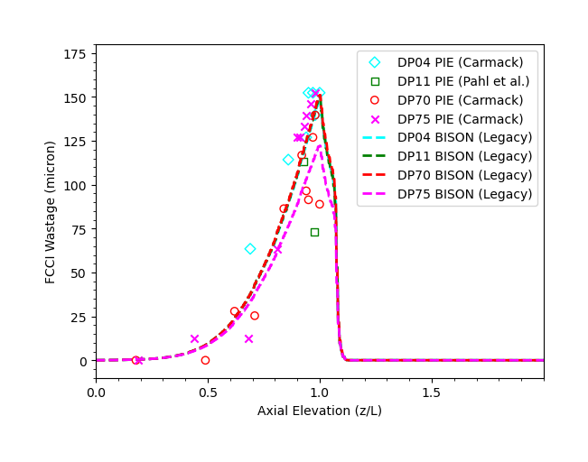
Figure 5: Comparison of the FCCI wastage thickness of four pins irradiated in X447/A between legacy BISON prediction and micrograph measurement.
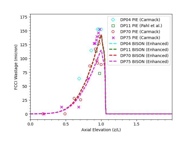
Figure 6: Comparison of the FCCI wastage thickness of four pins irradiated in X447/A between enhanced BISON prediction and micrograph measurement.
The FCCI wastage thickness profiles predicted by BISON are compared with the experimental measurement on micrograph photos of the sectioned irradiated fuel pins. As shown in Figure 5 and Figure 6, BISON prediction with the legacy assessment case is quite consistent with the measurement data, providing a foundation for reliable prediction of cladding deformation due to FCCI thinning. For the enhanced assessment case, these predictions changed a little bit, leading to slightly lower predictions. Although the overall FCCI prediction is still consistent with the measured data, the slight underestimation could result in a slight underestimation in consequent cladding deformation. It is worth mentioning here that the parameters of the FCCI correlation were optimized using the legacy model set. On the other hand, the CCCI wastage formation was found to be 20 microns near the cladding outer surface elevation corresponding to the top of the fuel, which is also consistent with the BISON prediction.
Cladding Hoop Strain
In X447, a major consequence of cladding thinning, mainly due to FCCI, is the degradation in cladding's mechanical strength and thus enhancement in cladding deformation caused by accumulated fission gas within the cladding. As the FCCI is only severe near the cladding inner surface corresponding to the top section of the fuel slug, the cladding deformation is also prominent in this region. As shown by the blue curves in Figure 7 and Figure 8, the majority of the cladding only experienced minor deformation after the 10% burnup. On the other hand, near the top of the fuel slug, prominent cladding deformation up to 2.0% strain was observed. Unlike other fuel irradiation experiments, where the cladding stayed far away from the the creep rupture domain, the cladding in X447 was observed to be subjected to breaching due to creep rupture. In that case, tertiary creep was expected to make significant contributions to the cladding deformation. In Figure 7 and Figure 8, using the enhanced model, it is prominent that taking into account the tertiary creep, the predicted cladding deformation is more consistent with the profilometry measurement. Additionally, it is worth mentioning that the measured cladding deformation values shown in Figure 7 and Figure 8 are the circumferentially maximum values, the corresponding minimum peak values are 2.956 mm and 2.963 mm (compared to 2.967 mm and 2.977 mm) for DP04 and DP11, respectively.
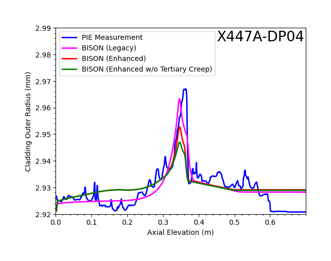
Figure 7: BISON predicted cladding deformation for legacy and enhanced (with and without tertiary cladding creep) models compared with profilometry measurement (DP04).
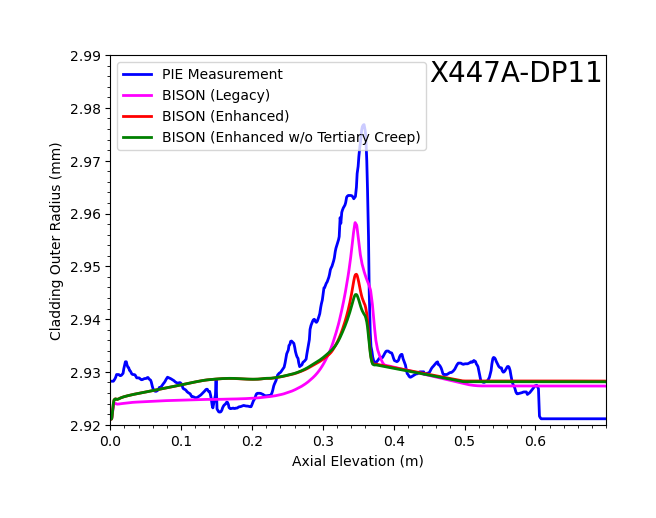
Figure 8: BISON predicted cladding deformation for legacy and enhanced (with and without tertiary cladding creep) models compared with profilometry measurement (DP11).
Leveraging the FIPD-BISON integration framework, BISON is capable of predicting such cladding deformation behavior that is comparable to the profilometry measurement results. Furthermore, modeling changes introduced in the enhanced assessment case only change these radial deformation predictions by approximately 0.01 mm. It is noticeable that the current BISON model predicts lower cladding strain compared to the PIE measurement, which will be discussed later.
Fuel Axial Elongation
An improvement of the enhanced X447 case over the legacy model is the calculation of non-recoverable axial fuel elongation, which is the final fuel elongation minus thermal expansion. As shown in Figure 9 and Figure 10, the legacy penalty formulation overpredicts fuel elongation, whereas the enhanced model, whose elongation estimate is tightly controlled by the combined effects of the fuel anisotropic swelling factor and the fuel-clad tangential contact coefficient of friction, more closely matches the PIE measurement, which is plotted with dashed black lines. It is also worth mentioning that tertiary creep of cladding has marginal effects on fuel axial elongation.
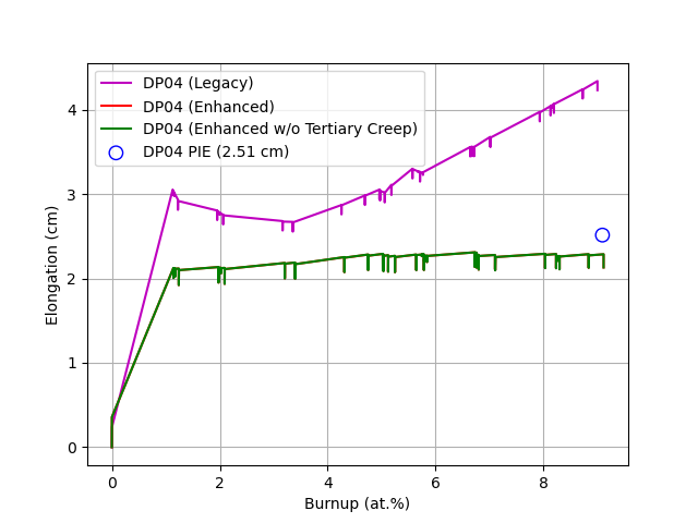
Figure 9: BISON predicted fuel elongation compared with profilometry measurement (DP04).
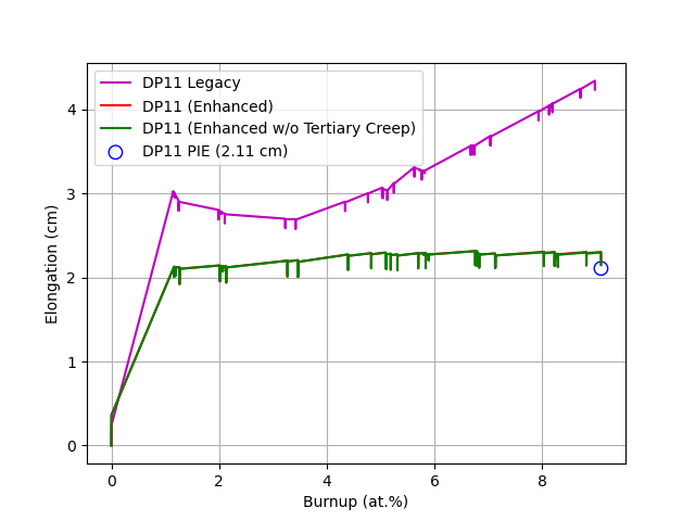
Figure 10: BISON predicted fuel elongation compared with profilometry measurement (DP11).
Statistics of Pin Failure
Under the legacy Integrated Fast Reactor (IFR) program, two pin failure criteria were developed for normal operation condition based on HT9 cladding damage Briggs et al. (1995):
Thermal component of plastic hoop strain during normal operation is less than 1%.
CDF during normal operation is less than 0.05.
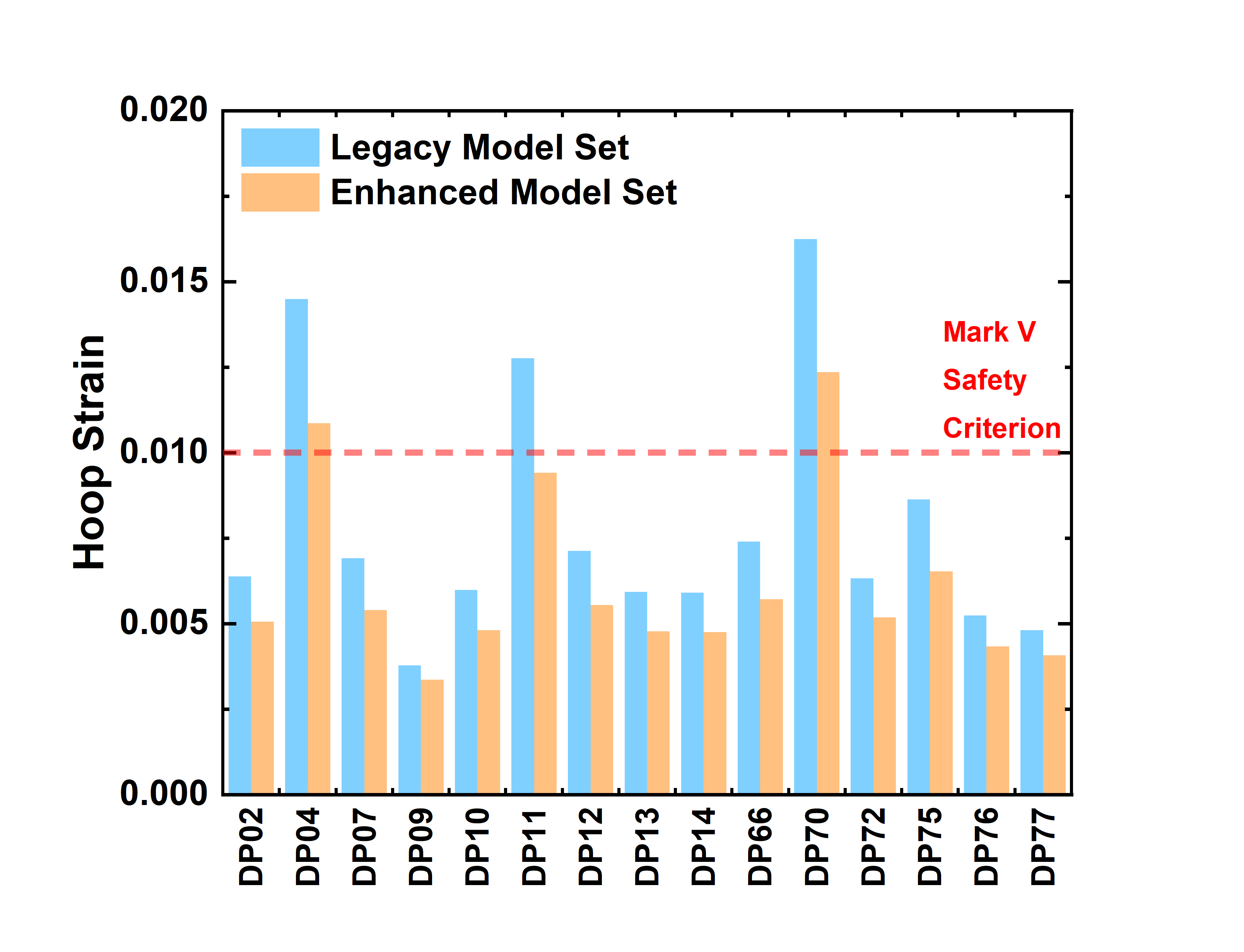
Figure 11: The maximum cladding hoop strain values (percentage) predicted for the X447/A subassembly. The red line indicates the fuel safety criterion defined for the EBR-II Mark V driver fuel during the IFR program (Briggs et al., 1995).
For the first criterion, the maximum predicted cladding hoop strain values are illustrated in Figure 11. Under the high cladding temperature conditions involved in the experiment X447, the cladding hoop strain is dominated by thermal creep. It is noticeable that the two failed pins (i.e., DP70 and DP75) and their sibling pins (i.e., DP04 and DP11) have highest predicted cladding hoop strain values, showing the consistence with experimental observation. Additionally, three out of these four pins have maximum cladding hoop strain approaching or exceeding the failure criterion of 1%. While BISON prediction provides correct trends and consistence, it is worth noting that the 1% criterion is conservative because the actual observed failure starts at ~2%. As shown in Figure 7 and Figure 8, current models still slightly underestimate hoop strain, as the PIE measured circumferential peak strain values of some pins do exceed 2%.
On the other hand, the maximum predicted CDF values are listed in Figure 12. Based on the enhanced model, the two failed pins and their sibling pins are the only four pins with CDF values exceeding the failure criterion of 0.05, which is again consistent with the experimental observation. When the CDF based criterion was established, a statistical relation between CDF and cladding failure probability was developed based on the long-term thermal creep rupture experiment results of unirradiated HT9 specimens, as shown in Figure 13. Based on this correlation, the BISON predicted CDF values, especially the enhanced model, correspond to a failure probability that is much lower than the observed 2 out of 15 pins. Similar underestimation in CDF was also reported in the original IFR documentation (Briggs et al., 1995) when using LIFE-METAL, which is potentially related to the limitations of the experimental data used for developing the correlation (e.g., unirradiated specimens).
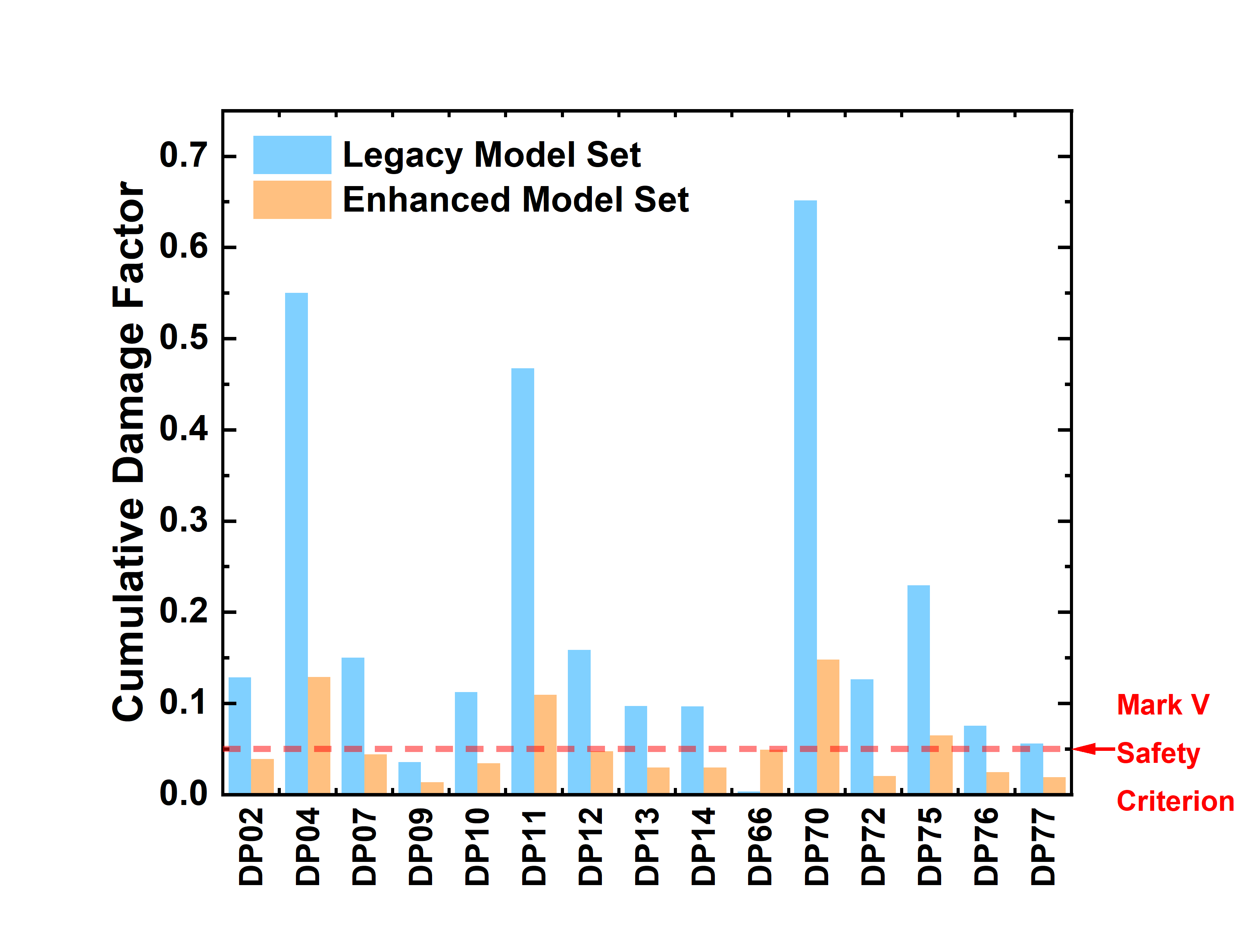
Figure 12: Cumulative Damage Factors values for the X447/A subassembly. The red line indicates the fuel safety criterion defined for the EBR-II Mark V driver fuel during the IFR program (Briggs et al., 1995).
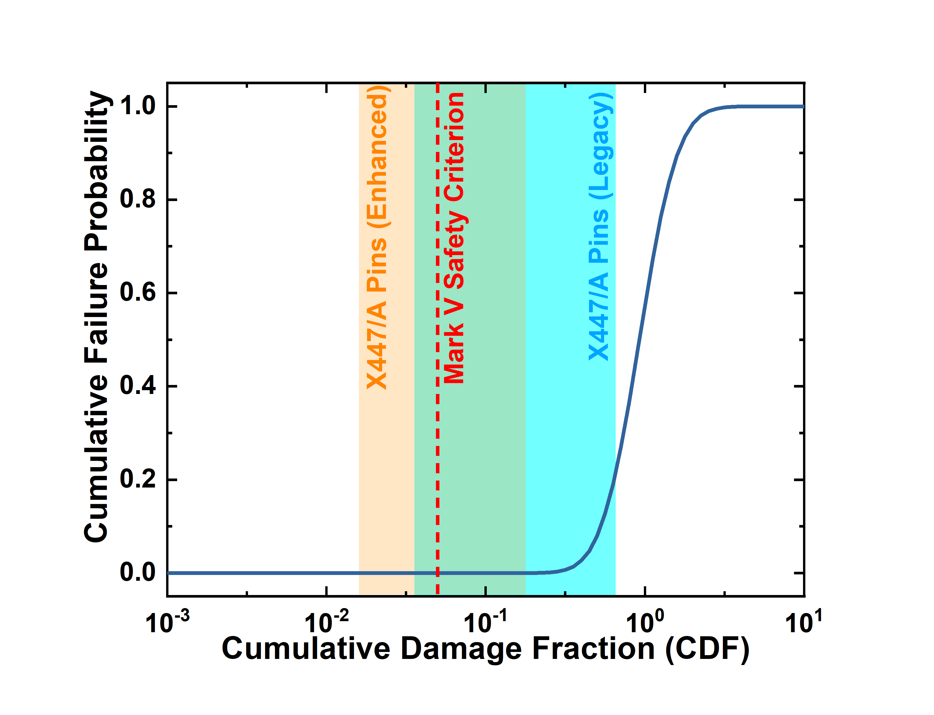
Figure 13: The correlation between CDF and failure probability with CDF ranges predicted for X447/A pins included. The red line indicates the fuel safety criterion defined for the EBR-II Mark V driver fuel during the IFR program (Briggs et al., 1995).
Discussion
This assessment case, enhanced with automatic differentiation and mortar mechanical contact, demonstrates improved problem convergence and fuel-clad contact enforcement with negligible changes to solution accuracy. FCCI wastage thickness profiles and cladding hoop strain remain generally consistent with the experimental measurement with some limited discrepancies. Furthermore, with enhanced contact modeling, fuel axial elongation calculations more closely resemble PIE measurements. The pins experiencing different temperature and burnup show different deformation as observed in the PIE data.
Finally, the enhancements made to the assessment case cause an underprediction in fuel pin cladding failure based on both cladding hoop strain and CDF criteria. The potential primary sources of such discrepancies could include: that the current HT9 creep model can be improved; that the FCCI-based cladding damage involves more complex failure mechanisms instead of simple creep rupture; and that the local details that are not covered by the adopted 2D-RZ model (e.g., preferential FCCI at some circumferential locations and thermal effects from the spacer wire). These factors should be improved with the currently in-development advanced microstructure-informed creep models as well as the potential 3D modeling approach.
References
- K. L. Basehore and N. E. Todreas.
SUPERENERGY-2: A multiassembly, steady-state computer code for LMFBR core thermal-hydraulic analysis.
Technical Report, Battelle Pacific Northwest Labs., Richland, WA (USA), 1980.
doi:10.2172/5107861.[BibTeX]
- L. L. Briggs, L. K. Chang, and D. J. Hill.
Safety Analysis and Technical Basis for Establishing an Interim Burnup Limit for Mark-V and Mark-VA Fueled Subassemblies in EBR-II.
Technical Report ANL-NSE-1, Argonne National Laboratory, 1995.[BibTeX]
- Alexander Lindsay, Roy Stogner, Derek Gaston, Daniel Schwen, Christopher Matthews, Wen Jiang, Larry K. Aagesen, Robert Carlsen, Fande Kong, Andrew Slaughter, Cody Permann, and Richard Martineau.
Automatic differentiation in metaphysicl and its applications in MOOSE.
Nuclear Technology, 207(7):905–922, 2021.
URL: https://doi.org/10.1080/00295450.2020.1838877, doi:10.1080/00295450.2020.1838877.[BibTeX]
- Christopher Matthews, Stephen Novascone, Al Casagranda, Larry Aagesen, Cetin Unal, and David Andersson.
Development and formulation of physics based metallic fuel models and comparison to integral irradiation data.
Journal of Nuclear Materials, 578:154343, 2023.
URL: https://www.sciencedirect.com/science/article/pii/S0022311523001137, doi:https://doi.org/10.1016/j.jnucmat.2023.154343.[BibTeX]
- Y. Miao, A. Oaks, K. Mo, M. Billone, C. Matthews, A. X. Zabriskie, S. Novascone, and A. M. Yacout.
Metallic fuel cladding degradation model development and evaluation for BISON.
Nuclear Engineering and Design, 385:111531, 2021.
doi:10.1016/j.nucengdes.2021.111531.[BibTeX]
- R. G. Pahl, C. E. Lahm, and S. L. Hayes.
Performance of HT9 clad metallic fuel at high temperature.
Journal of Nuclear Materials, 204:141–147, 1993.
doi:10.1016/0022-3115(93)90210-P.[BibTeX]
- A. Recuero, A. Lindsay, D. Yushu, J. W. Peterson, and B. Spencer.
A mortar thermomechanical contact computational framework for nuclear fuel performance simulation.
Nuclear Engineering and Design, 394:111808, 2022.
doi:10.1016/j.nucengdes.2022.111808.[BibTeX]
- Abdellatif M Yacout, Kun Mo, Aaron Oaks, Yinbin Miao, Tanju Sofu, and Walid Mohamed.
FIPD: the SFR metallic fuels irradiation & physics database.
Nuclear Engineering and Design, 380:111225, 2021.[BibTeX]