EBR-II X441 Experiment
Overview
The X441 experiment in EBR-II contained a series of fuel pin design changes to determine the effect of plenum/fuel volume ratio, fuel smear density, zirconium content, cladding material and cladding thickness. The fuel pins were examined at interim times to check for cladding deformation or breach. The cladding hoop strain at EOL was used to measure the effect of the fuel pin design changes tested in this experiment. The specific fuel pin design changes for each group are listed in Table 1.
Table 1: X441 Group Description
| Group | Plenum/Fuel (Vol. Ratio) | Zr content (w/o) | Smear Density (% TD) | Clad Material | Clad Thickness (mils) |
|---|---|---|---|---|---|
| A | 1.5 | 10 | 75 | HT9 | 15 |
| B | 2.1 | 10 | 75 | HT9 | 15 |
| C | 1.1 | 10 | 75 | HT9 | 15 |
| D | 1.5 | 6 | 75 | HT9 | 15 |
| E | 1.5 | 14 | 75 | HT9 | 15 |
| F | 1.5 | 10 | 85 | HT9 | 15 |
| G | 1.5 | 10 | 70 | HT9 | 15 |
| H | 1.5 | 10 | 75 | HT9 | 18 |
| I | 1.5 | 14 | 75 | D9 | 15 |
| J | 1.5 | 10 | 75 | D9 | 15 |
| K | 1.5 | 6 | 75 | D9 | 15 |
Test Description
The X441 experiment consisted of a 61-pin bundle irradiated in EBR-II under steady-state conditions to a target burnup of . The main objective of the experiment was to determine a design envelope for ternary (U-Pu-Zr) fuel design in EBR-II. The fuel design parameters that were varied include the plenum/fuel volume ratio (1.1, 1.5 and 2.1), fuel smear density (70, 75 and 85% TD), Zr content (6, 10 and 14 wt. %), cladding thickness (0.015 and 0.018 in.) and cladding material (HT9 and D9). Additional goals of this experiment were to provide more input for optimization of U-Pu-Zr fuel and experimental data for validating fuel performance codes.
Rod Design Specifications
Operating Conditions and Irradiation History
The actual power history for specific EBR-II experiments is still being determined. Therefore, a simplified power history containing an initial ramp to power and hold for a given amount of time with a final power down is being used. The average burnup of the fuel at the end of the simulation is used as a check that the power history is reasonable.
Model Description
Geometry and Mesh
The 2D-RZ meshes for these cases are generated with the internal smeared pellet meshing capability in BISON FuelPinMeshGenerator. The 1.5D versions of these models are created using the layered 1D mesh feature Layered1DMeshGenerator. All of the dimensions and meshing details are contained in the Mesh block. However, some of these quantities have been parameterized due to the similarity of the fuel rod design for each of the groups.
Material and Behavioral Models
The following material and behavioral models for the UPuZr fuel were used in these cases:
UPuZrElasticityTensor: Elastic mechanical properties
UPuZrCreepUpdate: Creep mechanical properties and deformation behavior
UPuZrGaseousEigenstrain: Calculates the change in volume due to gaseous fission product production in UPuZr
UPuZrFissionRate: Computes fission rate based on linear power, axial power profile and Pu and Zr concentrations
UPuZrBurnup: Computes the burnup for UPuZr metallic fuel
BurnupDependentEigenstrain: Calculates the change in volume due to solid fission product production in UPuZr
UPuZrThermal: Calculates the thermal conductivity and specific heat for UPuZr fuel
ComputeThermalExpansionEigenstrain: Thermal expansion model with constant instantenous thermal expansion coefficient
UPuZrFissionGasRelease: Fission gas release model for UPuZr metallic fuel
The following material and behavioral models for the HT9 cladding were used in these cases:
ComputeIsotropicElasticityTensor: Isotropic elastic mechanical properties
HT9CreepUpdate: Creep mechanical properties and deformation behavior
ComputeThermalExpansionEigenstrain: Thermal expansion model with constant instantenous thermal expansion coefficient
HT9FailureClad: Failure model for HT9 cladding
Input files
The parameratized input files for the 1.5D and 2D-RZ variations are located at bison/assessment/metallic_fuel/EBRII/X441/analysis. The specific differences between each of the groups are contained in the files ending with .params located in each subdirectory. The 2D-RZ models share a single .params file while the 1.5D model has a separate .params file.
Results Comparison
Cladding Hoop Strain
The primary experimentally measured quantity used to compare the various design parameter changes was the maximum cladding strain. Since the main objective was to determine the design envelope for the fuel and that a clad breech was the primary failure mode of the fuel pin, the maximum cladding strain correlated well with failure.
The plots below show the comparison of the BISON predictions for cladding strain with the experimentally measured values from the X441 experiment.
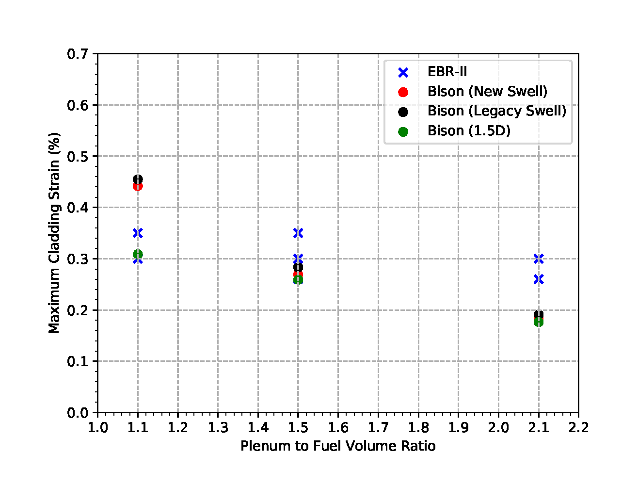
Figure 1: Comparison of maximum cladding strain as a function of plenum/fuel volume ratio
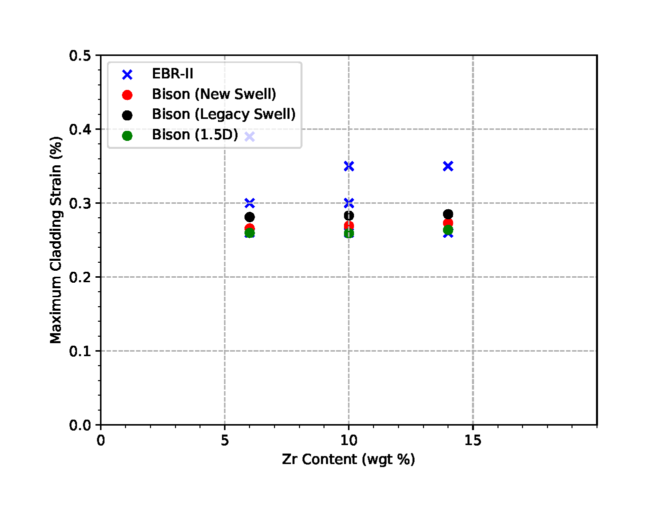
Figure 2: Comparison of maximum cladding strain as a function of Zr content
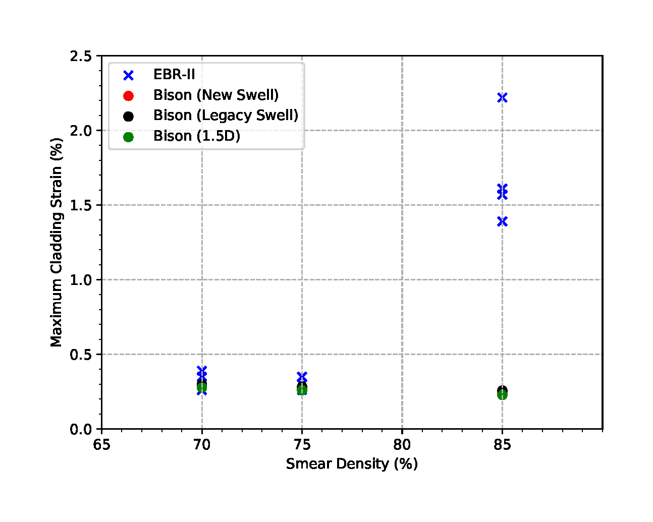
Figure 3: Comparison of maximum cladding strain as a function of smear density
Discussion
The BISON predictions for the cladding strain over the range of design groups is fairly good. The primary exception is the case with smear density as shown in Figure 3. However, this should be improved with the addition of an anisotropic swelling model for the fuel and including frictional contact in the simulation.