EBR-II X423 Experiment
A Metal Fuel Assessment Case Focused on Low Burnup Swelling Model Evaluation.
Overview
The IFR (Integral Fast Reactor) Experiment X423/A/B/C was selected to form an assessment case with a focus on the evaluation of the low-burnup metallic fuel swelling models. 58 metallic fuel pins, which include both binary (U-10Zr) and ternary (U-xPu-10Zr) alloys with various Pu percentages, were irradiated in the X423 subassembly. The X423 experiment used large diameter fuel pins ("fat" pins) and adopted EBR-II's D-37 subassembly hardware to contain these larger pins. As the name implies, the X423 subassembly contains 37 fuel pins and three reconstitutions were performed (labelled A, B, and C) so that a total of 58 fuel pins were irradiated up to approximately 5% atomic burnup. See Table 1 for more details about this experiment.
Table 1: Nominal Design Features of the X423 Fuel Pins
| Item | Value | Unit | Comments |
|---|---|---|---|
| Assembly Hardware | D-37 | n/a | 37 pins |
| Reconstitution | 3 | times | labelled as X423, X423A, X423B, and X423C |
| Fuel Alloys | U-xPu-10Zr | n/a | x = 0, 3, 8, 19, 22, 26 |
| Fuel Enrichment | 37, 34, 16, 13, and 6 | % U/U | various enrichment for different Pu content to achieve similar pin power |
| Fuel Slug Length | 13.5 | inch | standard EBR-II fuel length |
| Fuel Slug Diameter | 0.223 | inch | "fat" fuel |
| Fuel Slug Mass | 136 | g | |
| Sodium Fill Level | 0.25 | inch | Distance above the fuel slug top |
| Cladding Material | 316SS | n/a | 20% cold working (CW) |
| Cladding Outer Diameter | 0.290 | inch | |
| Cladding Wall Thickness | 0.016 | inch | |
| Spacer Wire Diameter | 0.057 | inch | |
| Spacer Wire Pitch | 6.00 | inch | |
| Fuel Element Mass | 202 | g | |
| Fuel-to-Plenum Volume Ratio | 1.07 | n/a | at 25C |
Test Description
X423 was designed to test the large pin performance as well as the low-burnup metallic fuel swelling behavior. By the time this experiment was designed, it had been known that metallic fuel swells rapidly at low burnup and closes the fuel-cladding gap within merely 2% burnup. Another feature of the fuel swelling is that the fuel grows anisotropically with a preferential radial growth direction. Once the fuel-cladding gap is closed, the further fuel swelling is coupled with complex mechanical interaction between fuel and cladding. However, a restriction-free fuel is ideal for fuel swelling model development, calibration, verification and validation. Therefore, the X423 experiment was designed to investigate the fuel swelling behavior before the fuel-cladding gap is closed.
To achieve this, the reconstitution was designed to allow intermediate post-irradiation examination at very low burnup points (~0.5%, ~1.0%, ~2.0%, etc.). During each reconstitution, all the pins were investigated by neutron radiography (NRAD) providing a non-destructive approach to measuring fuel dimensional changes. A selection of the irradiated fuel pins were also investigated using destructive approaches for more details and these pins were replaced by fresh fuel pins.
As all the pins irradiated in X423 have NRAD measured pin dimension at all reconstitution periods, all the 58 fuel pins are simulated in this assessment case.
BISON-FIPD Integration
Many crucial fuel performance behaviors are highly sensitive to temperature and irradiation dose history. Hence, high-fidelity irradiation condition data and fuel design parameters are crucial for fuel performance code calibration, verification and validation (V&V). Meanwhile, comprehensive post-irradiation examination (PIE) data collected after the irradiation experiment are key references for assessing fuel performance models. As part of the legacy IFR program, these data about the IFR experiments conducted at EBR-II, including the X423/A experiment, are being recovered and maintained in Argonne National Laboratory’s SFR Fuel Irradiation & Physics Database (FIPD) (Yacout et al., 2021). The quality assurance efforts are on-going to eventually make FIPD data conformant with the requirements of the ASME NQA-1 Standard. To facilitate the use of these data stored in FIPD for BISON metallic fuel model V&V, efforts have been made on both FIPD and BISON sides through the BISON-FIPD integration project. This X423 assessment case is powered by these BISON-FIPD integration accomplishments, and thus is a demonstration case of the integration. The FIPD-based data as well as the related BISON/MOOSE classes used to handle those data are listed in Table 2.
Table 2: Use of BISON-FIPD Integration for X423 Assessment Case
| FIPD-Based Data Type | Related BISON/MOOSE Class | Category of Data |
|---|---|---|
| Fuel Pin Design Data | FIPDRodletMeshGenerator | Pin Design & Geometry |
| Fuel Pin As-Build Radius Profile | FIPDRodletMeshGenerator | Pin Design & Geometry |
| Time-Varying Pin-Averaged Power | PiecewiseLinear | Irradiation Conditions |
| Time-Varying Pin-Averaged Fast Neutron Flux | PiecewiseLinear | Irradiation Conditions |
| Power Peaking Factor | FIPDAxialProfileFunction | Irradiation Conditions |
| Fast Neutron Flux Peaking Factor | FIPDAxialProfileFunction | Irradiation Conditions |
| Time-Varying Cladding Outer Surface Temperature | FIPDAxialProfileFunction | Irradiation Conditions |
| Axial-Dependent Fuel Radius and Fuel Length | FIPDAxialPIEComparison | Post-Irradiation Examination Data |
While all the Fuels Irradiation and Physics Database (FIPD) data mentioned in Table 1 are available for downloading as CSV files on the FIPD website, those CSV data files that are needed by the BISON assessment cases are simultaneously maintained in a separate repository called FIPD-BISON Integration Data. This repository is set as an optional submodule of the BISON code. Any users who want to run this X447 assessment case must activate this submodule. All FIPD users can request the access to this repository.
Pin Design Parameters
All the fuel pin design data of this assessment case are adopted from the FIPD database. Multiple versions of pin design data are available in FIPD, including nominal design description, as-built design specifications, and measured fabrication data. As-built design specifications are used in this assessment case due to their consistence and completeness. For each of the 58 pins involved in this assessment case, a separate CSV file available in the FIPD-BISON Integration Data is read by BISON's FIPDRodletMeshGenerator to generate the axisymmetric (RZ) 2D mesh as well as the corresponding MeshMetaData.
Radial fuel swelling at low burnup before fuel-cladding gap closure is the focus of this assessment case. Therefore, it is important to get accurately measured fuel radius prior to the irradiation. For all the X423 fuel pins, the radius profile of each as-fabricated fuel slug was measured using a micrometer at multiple axial positions. This as-fabricated fuel radius profile information is provided to FIPDRodletMeshGenerator in addition to the conventional pin design fuel so that the mesh generator can generate a fuel mesh that is consistent to the provided radius profile.
Operating Conditions and Irradiation History
Calculated pin-by-pin operating conditions data from the FIPD database are used in this assessment case. For each pin, time-varying pin-averaged power and fast neutron flux information are used along with corresponding axial peaking factors to provide complete time and axial dependent irradiation condition profiles. Also, Due to the existence of the reconstituted pins in the experiment X423, BISON's intrinsic coolant channel models might not make best prediction, especially when the neighboring fuel pins have dissimilar power profiles. In that case, time-varying cladding outer surface temperature available in the FIPD database, which is calculated by thermal hydraulics code SuperEnergy2 (Basehore and Todreas, 1980), is used directly as the temperature boundary conditions. The approaches of using FIPD-based operating condition and irradiation history data for this X423 assessment are identical to those of the X447 Assessment Case
Post-Irradiation Examinations
The main focus of this assessment case is the fuel swelling strain in both radial and axial directions, especially before the fuel-cladding gap is closed. The fuel dimensional changes were measured by NRAD. Two types of NRAD images were taken simultaneously, thermal neutron images through Dy (dysprosium) plates and epithermal neutron images through In (indium) plates. As fissile materials have large capturing cross sections for thermal neutrons, Dy-NRAD is particularly useful to image the nuclear fuels. Thus, the Dy-NRAD was used as a non-destructive examination method to measure fuel dimensional changes.
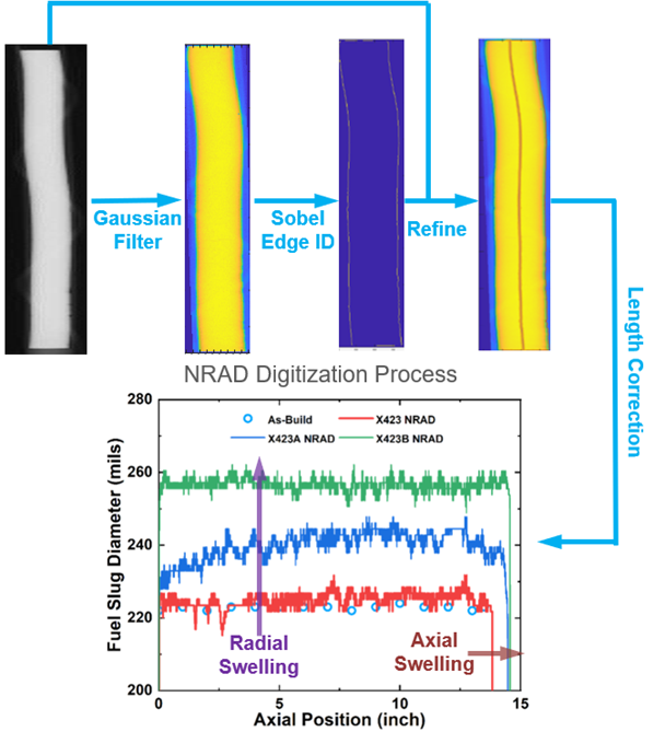
Figure 1: NRAD data processing and its application in swelling model evaluation.
For all the 58 fuel pins irradiated in the X423 experiment, the Dy-NRAD and In-NRAD images were taken during each reconstitution and after the irradiation. Therefore, a total of 148 sets of NRAD data are available in FIPD. These Dy-NRAD images have been processed and analyzed using a Canny edge detection algorithm. To be specific, a combination of Gaussian filter and Sobel edge detection algorithms were adopted, as shown in the upper half of Figure 1. The processed NRAD data is a fuel radius profile as a function of the elevation position, whereas the fuel axial growth information is implicitly contained as the length of the profile (i.e., maximum elevation position). The processed data of all the 148 related NRAD measurement results are available in FIPD and used in this assessment case for comparison with the fuel swelling strain predicted by BISON.
In the FIPD-BISON Integration Data, the fuel radius profile based on Dy-NRAD imaging is provided in a single CSV file for each pin during each reconstitution or after the irradiation. The data can be loaded by FIPDAxialPIEComparison to be directly compared with the BISON predictions, including both radial and axial fuel swelling strain, as shown in the lower half of Figure 1. An axial-dependent fuel radius profile will be generated and compared with the NRAD-based data as a VectorPostprocessor. Additionally, a series of Postprocessors will be created by FIPDAxialPIEComparison to compare axial fuel swelling related quantities such as axial fuel growth and anisotropic swelling factor.
Model Description
Geometry and Mesh
The 2D-RZ meshes for the X423 pins are generated with the intrinsic rodlet meshing capability in BISON's FIPDRodletMeshGenerator. The mesh generator directly reads the FIPD-based pin design parameter CSV file as well as the as-fabricated fuel radius profile CSV file, and thus generates the mesh along with a series of MeshMetaData to help ensure consistent use of pin geometry data throughout the simulations. Additionally, the as-fabricated fuel radius profile is also provided as a MeshMetaData to be used by FIPDAxialPIEComparison for comparison.
Material and Behavioral Models
Two metallic fuel swelling models available in BISON are covered in this assessment case:
an empirical swelling and fission gas release transplanted from LIFE-METAL without automatic differentiation (AD);
a simplified viscoplasticity swelling model partially informed by lower-length scale (LLS) simulation results with AD.
The Non-AD LIFE-METAL Empirical Correlation Approach
The following material and behavioral models for the UPuZr fuel were used in these cases:
ADUPuZrElasticityTensor: Isotropic elastic mechanical properties
UPuZrCreepUpdate: Creep mechanical properties and deformation behavior
UPuZrVolumetricSwellingEigenstrainLM: Calculates the change in volume due to gaseous and solid fission product production in UPuZr (legacy correlation from LIFE-METAL)
UPuZrFissionRate: Computes fission rate based on linear power, axial power profile and Pu and Zr concentrations
UPuZrBurnup: Computes the burnup for UPuZr metallic fuel
UPuZrThermal: Calculates the thermal conductivity and specific heat for UPuZr fuel
ComputeThermalExpansionEigenstrain: Thermal expansion model with constant instantaneous thermal expansion coefficient
FgrUPuZrLM: Fission gas release model for UPuZr metallic fuel (legacy correlation from LIFE-METAL)
The following material and behavioral models for the SS316 cladding were used in these cases:
SS316ElasticityTensor: Elastic mechanical properties. These properties are locally scaled by MetallicFuelWastageDegradationFunction to account for cladding thinning caused by FCCI/CCCI. Note that neither FCCI nor CCCI are prominent in X423 due to the low burnup and relatively low irradiated temperature.
SS316CreepUpdate: Creep mechanical properties and deformation behavior. These properties are locally scaled by MetallicFuelWastageDegradationFunction to account for cladding thinning caused by FCCI/CCCI. Note that neither FCCI nor CCCI are prominent in X423 due to the low burnup and relatively low irradiated temperature.
SS316VolumetricSwellingEigenstrain: Unlike tempered martensitic cladding material HT9, as an austenitic stainless steel, the SS316 cladding as used in the X423 experiment is subject to prominent void swelling under irradiation. At low burnup, although this cladding swelling effect is still minor, it is still simulated as an eigenstrain.
ComputeThermalExpansionEigenstrain: Thermal expansion model with constant instantaneous thermal expansion coefficient
SS316Thermal: Calculates the thermal conductivity and specific heat for SS316 cladding
D9FailureClad: Failure model for D9 cladding based on the steady-state CDF model. Note that the CDF of SS316 is regarded identical to that of D9, as suggested in the Metallic Fuel Handbook (Hofman et al., 2019).
MetallicFuelWastage: Calculates the FCCI wastage thickness; use MetallicFuelWastageDegradationFunction to apply the FCCI effect on cladding mechanical properties.
MetallicFuelCoolantWastage: Calculates the CCCI wastage thickness; use MetallicFuelWastageDegradationFunction to apply the CCCI effect on cladding mechanical properties.
The AD Simplified Viscoplasticity Approach
As the viscoplasticity-based fission gas models only work in the AD mode. AD versions of the fuel and cladding models mentioned above need to be used for the simplified viscoplasticity approach with several exceptions on the fuel swelling and fission gas release models.
ADSimpleFissionGasViscoplasticityStressUpdate: A simplified viscoplasticity based fission gas behavior model designed and parameterized for metallic fuels.
ADBurnupDependentEigenstrain: An eigenstrain object that produces data proportional to fuel burnup. Used here to account for solid fission product swelling, which is not covered by ADSimpleFissionGasViscoplasticityStressUpdate.
ADPorosityFromStrain: Calculates porosity based on the fission gas swelling strain.
ADUPuZrSodiumLogging: Calculates the sodium back-filling status based on the pore interconnectivity.
Input files
The parametrized input files for the 2D-RZ whole fuel pin models are located at bison/assessment/metallic_fuel/EBRII/X423/analysis. All the 58 pins are simulated using the same models. The specific differences between each of the pins are contained in the files ending with .params located in each subdirectory for each pin.
As mentioned above, all the needed FIPD data files are located in the bison/fipd-bison-integration-data/X423 submodule folder. FIPD users may manually download needed data files and modify assessment inputs to use these downloaded files if they do not have the fipd-bison-integration-data submodule setup.
Results Comparison
It is worth mentioning that as the gold files of X423 assessment case also contain a great number of PIE data from FIPD, they are also stored in the FIPD-BISON Integration Data submodule.
The comparison here is mainly on the statistic behavior of all the irradiated pins instead of specific pins to provide a general impression of the low-burnup swelling behavior. The focus of this assessment case is the swelling behavior of metallic fuel at low burnup. Therefore, the swelling at both radial and axial direction are discussed here along with the anisotropic swelling behavior.
Radial Swelling
For all the 58 pins irradiated in the X423 subassembly, the fuel radii at different axial elevations predicted by BISON are compared with the corresponding NRAD measurement data. For each data point, its local burnup is also collected and used as the main irradiation condition parameter. As six different Pu content levels were involved in the X423 experiment, the data are compared separately in Figure 2.
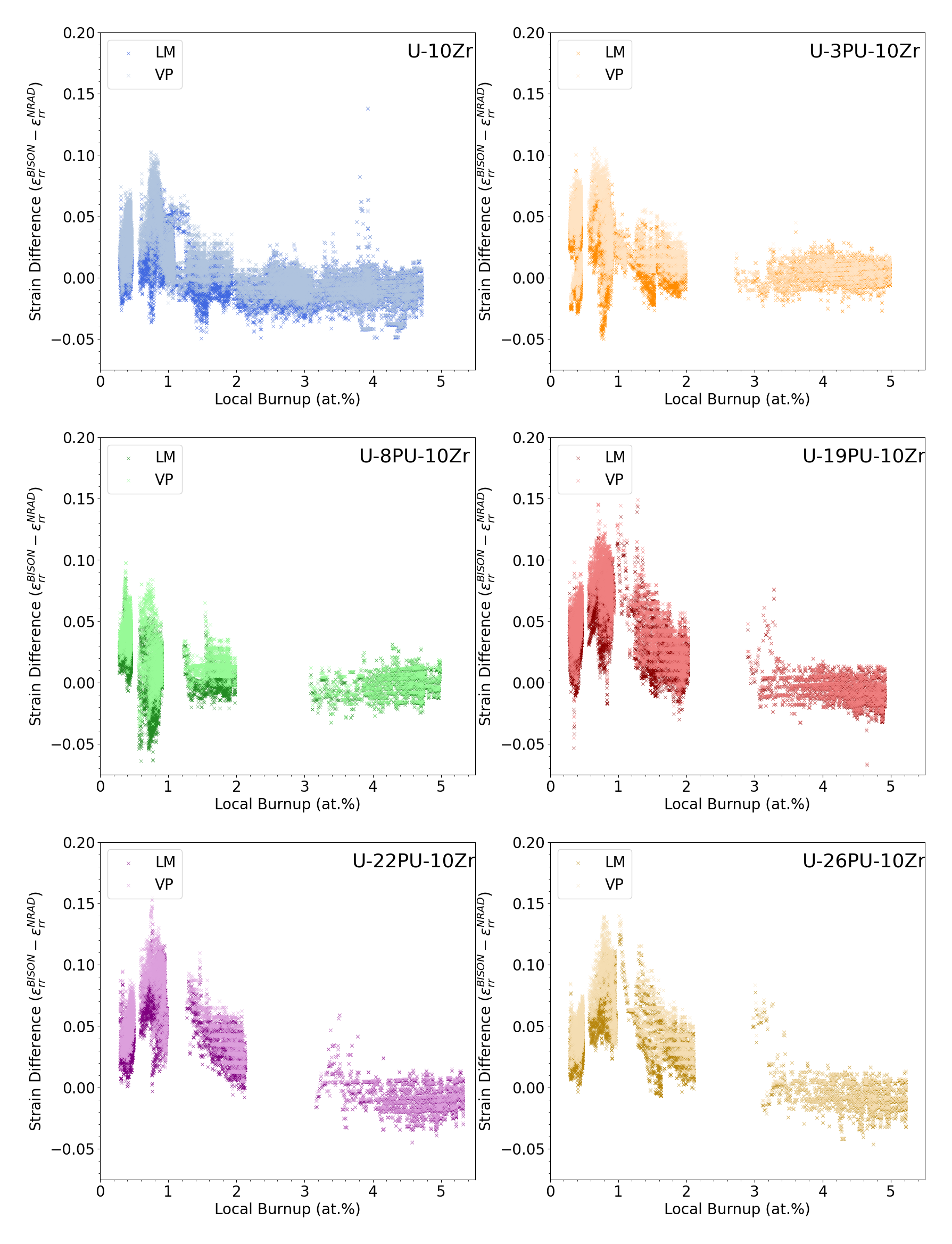
Figure 2: Comprehensive comparison of the difference between BISON predicted fuel radii using both LIFE-METAL fission gas model (LM) and viscoplasticity (VP) fission gas model and NRAD measured fuel radii of X423 pins.
It is prominent that the difference between BISON prediction and NRAD measurement becomes marginal as burnup exceeds approximately 2~3%. This is because the upper limit of radial swelling strain is defined by the inner diameter of the cladding. That is, once the fuel-cladding gap is closed, the difference is trivially marginal anyway.
On the other hand, prior to the gap closure event, both LM and VP fission gas models overestimate the radial swelling for all the Pu content level. As this overestimation gives a conservative prediction on swelling rate, both models are acceptable for safety related assessment. However, the future advanced mechanistic swelling model is expected to perform more accurate prediction to leave more design flexibility for advanced reactor developers.
Axial Swelling
The axial growth of the fuel pins predicted by BISON using the two models is also compared with the measured data based on the NRAD investigations. A comprehensive comparison is visualized in Figure 3, with a more detailed comparison illustrated in Figure 4
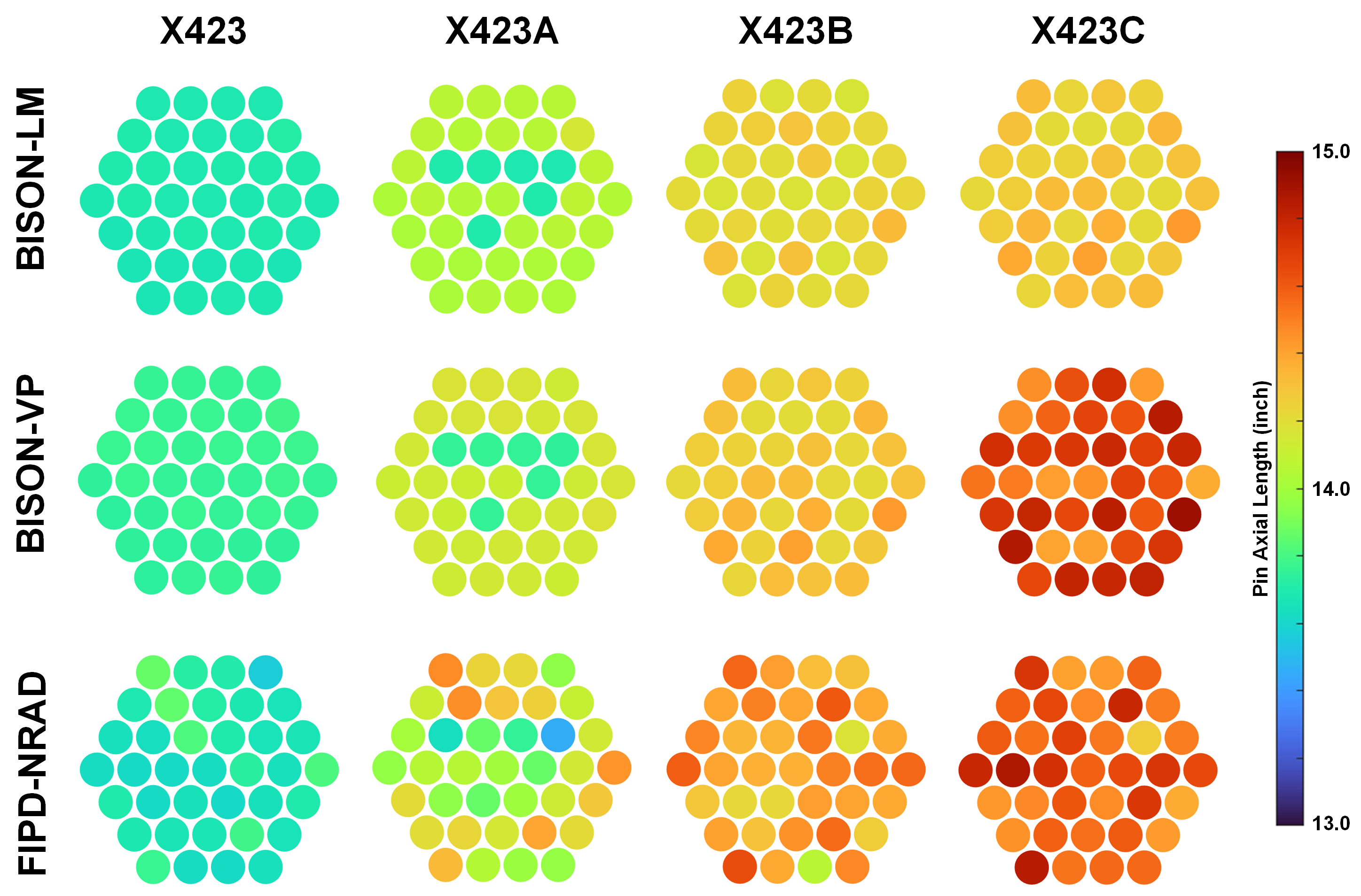
Figure 3: Fuel axial length measured by NRAD in comparison with the BISON predictions using the two swelling models (the length of each rod corresponds to the length of the irradiated pins beyond 33 inches. The color of the rod shows the local elevation so that the color of the top of each rod indicates the length of that rod).
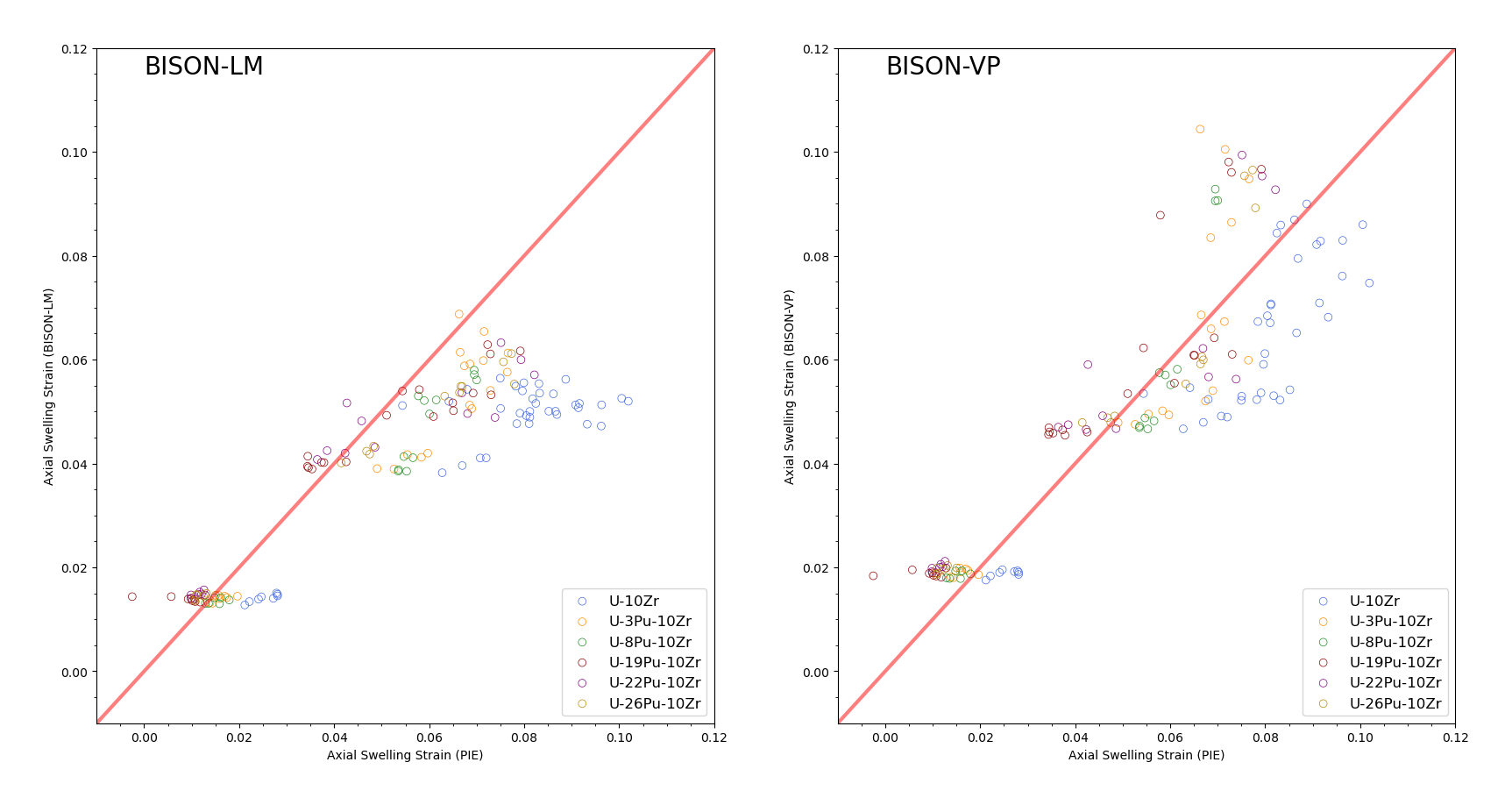
Figure 4: BISON predicted fuel axial swelling strain compared with NRAD measurement.
The LM model was found to predict axial growth at very low burnup (e.g., ~0.5%); it slightly underestimated the axial growth beyond ~2% burnup. On the other hand, the VP fission gas model slightly underestimates the axial growth at very low burnup but starts to catch up as the burnup increases and eventually slightly overestimates the axial growth at ~5% burnup. Despite the slight discrepancies, both models can still provide acceptable performance in predicting the axial swelling behavior. But the future advanced mechanistic swelling model is expected to outperform both models in accuracy. Also, the NRAD data show prominent Pu content dependence on axial swelling, whereas the current models do not include such dependence. This is another preferred feature of the advanced mechanistic model.
Volumetric Swelling
As the combined effect of the axial and radial swelling, the total volumetric swelling strain values of the X423 pins predicted by both BISON models are compared with the NRAD-based measurement values in Figure 5. As discussed previously in separate radial and axial swelling strains, both BISON models overestimate the early-stage swelling rate, providing conservative estimates. Meanwhile, future mechanistic swelling models are expected to provide more accurate predictions about metallic fuel's volumetric swelling at low burnup as well as capture Pu content effects.
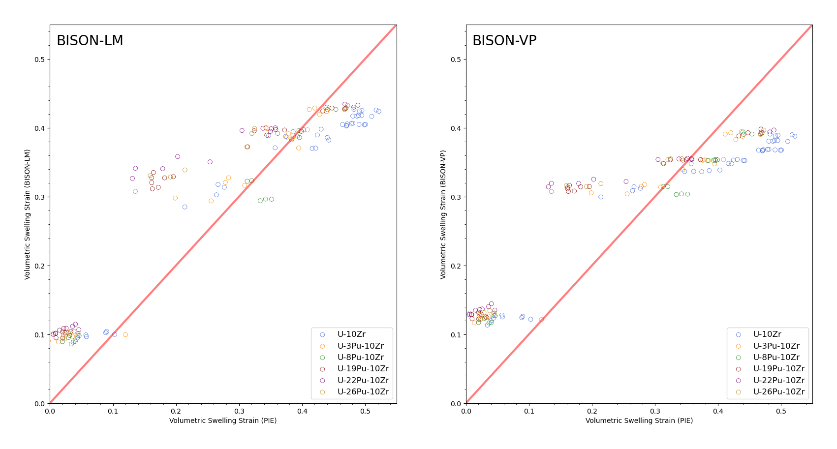
Figure 5: Volumetric swelling strain values of the X423 pins predicted by BISON using the two swelling models in comparison with the PIE NRAD measurement.
Anisotropy
Metallic fuel is well-known for its anisotropic swelling behavior featuring preferential radial swelling. To quantitatively describe such an anisotropic phenomenon, an anisotropic swelling factor () can be defined as follows,
(1) (2)
Note that the definition of anisotropic swelling factor is not unique. Here the definition used in UPuZrVolumetricSwellingEigenstrainLM is adopted. For the fuel pins irradiated in the X423 experiment, the NRAD images unveil the anisotropic factor as a function of burnup as shown in the left sub-figure of Figure 6.
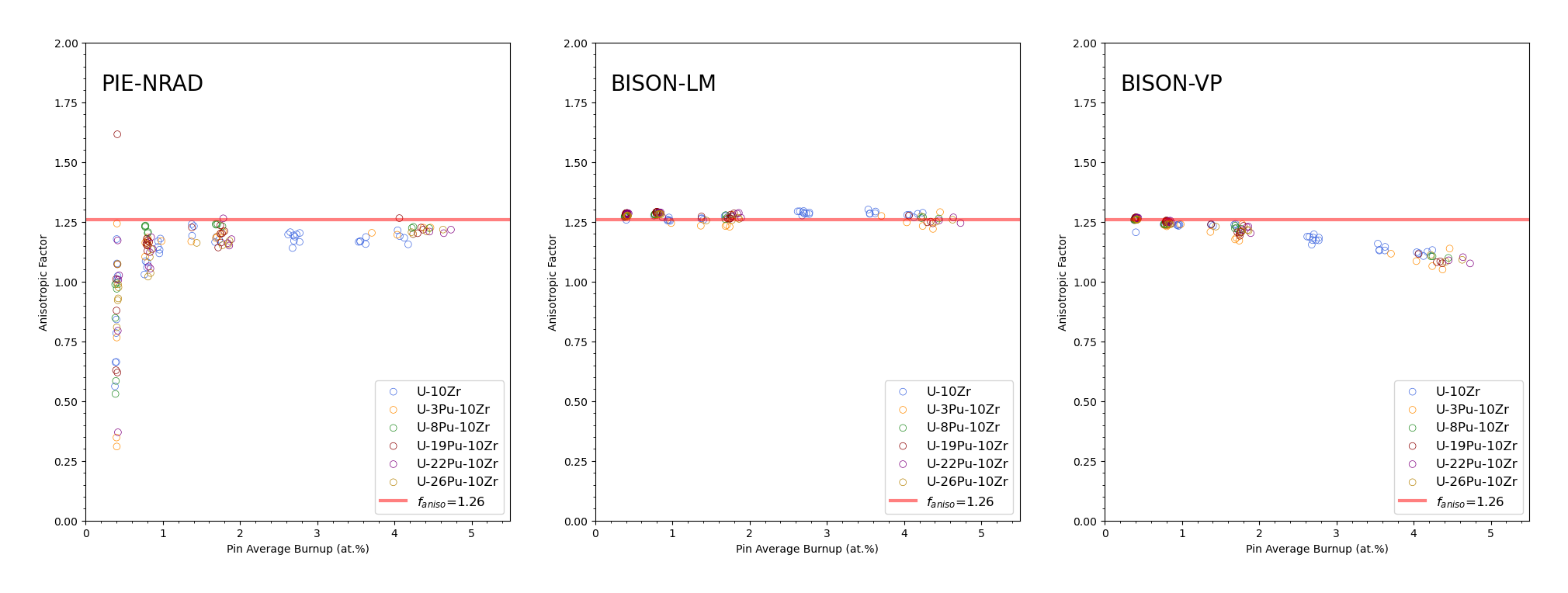
Figure 6: Anisotropic factor of fuel swelling for all the pins irradiated in X423: (left) experimental measurements by NRAD; (middle) predictions by BISON using the LIFE-METAL (LM) swelling model; (right) predictions by BISON using the simplified viscoplasticity (VP) model.
As the burnup exceeds 2%, the anisotropic swelling factor converges at a constant value of approximately 1.25. However, at the very low burnup (~0.5%), the anisotropic factor was found scattered and shows some dependence on Pu content.
The mechanism of such anisotropic swelling behavior has been assumed to originate from complex phase-specific behaviors at difference irradiation temperatures. But the detailed theory has never been established and confirmed. Therefore, a user-defined anisotropic swelling factor is usually enforced in fission gas swelling models. For example, in the LM model used in this assessment case, the anisotropic swelling factor is set as 1.25. As indicated in the middle sub-figure of Figure 6, the enforced factor is applied to the simulation effectively. On the other hand, the VP model adopts a different definition of anisotropic factor. However, the two definitions are inter-convertible. As shown in the right sub-figure of Figure 6, the anisotropic factor is also enforced effectively.
However, neither of the models are capable of replicating the complex and Pu-dependent anisotropic swelling behavior at very low burnup (see Figure 6), which is another expected feature of the future advanced mechanistic swelling model.
Discussion
The BISON predictions for both axial and radial swelling using the two existing sets of fission gas swelling models are generally consistent with the NRAD measurement beyond approximately 2% burnup. But discrepancies do exist between the simulation results and experimental observation at low burnup (<2%). In that case, BISON overestimates the radial swelling strain, which is acceptable as this is conservative. Additionally, the low-burnup anisotropic swelling behavior as well as the Pu effects on the swelling behavior are the gaps identified in this assessment case and need to be improved by any future advanced mechanistic swelling model.
References
- K. L. Basehore and N. E. Todreas.
SUPERENERGY-2: A multiassembly, steady-state computer code for LMFBR core thermal-hydraulic analysis.
Technical Report, Battelle Pacific Northwest Labs., Richland, WA (USA), 1980.
doi:10.2172/5107861.[BibTeX]
- G. L. Hofman, M. C. Billone, J. F. Koenig, J. M. Kramer, J. D. B. Lambert, L. Leibowitz, Y. Orechwa, D. R. Pedersen, D. L. Porter, H. Tsai, and A. E. Wright.
Metallic fuels handbook.
Technical Report ANL-NSE-3, Argonne National Laboratory, 2019.[BibTeX]
- Abdellatif M Yacout, Kun Mo, Aaron Oaks, Yinbin Miao, Tanju Sofu, and Walid Mohamed.
FIPD: the SFR metallic fuels irradiation & physics database.
Nuclear Engineering and Design, 380:111225, 2021.[BibTeX]