US PWR 16x16 Rods TSQ002 and TSQ022
Overview
The US PWR 16x16 lead test assembly (LTA) extended burnup demonstration (referred to as US PWR 16x16 from here on out) was conducted during the 1980's in a US commercial pressurized water reactor (PWR) (IAEA, 2008-2012). The purpose of this series of experiments was to increase final discharge burnup and to demonstrate improved fuel utilization through more efficient fuel management. Two rods out of this series, TSQ002 and TSQ022, were discharged at a burnup of approximately 58 MWd/kgU and are the subjects of this report. TSQ002 is a full length fuel rod with standard (solid) fuel pellets, whereas TSQ022 is a full length fuel rod with annular fuel pellets.
Test Description
Rod Design Specifications
As mentioned in the previous section, both rods considered in the US PWR16x16 experiment were full length rods. TSQ002 was a standard fuel rod with solid fuel pellets whereas TSQ022 had annular fuel pellets. Both fuel rods were clad with Zr-4. The rod specifications are tabulated in Table 1.
Table 1: Rod Specifications for US PWR 16x16 rods TSQ002 and TSQ022.
| Fuel Rod | Measurement | Unit |
|---|---|---|
| Overall length | 4.094 | m |
| Fuel stack height | 3.81 | m |
| Nominal plenum height | 284 | mm |
| Number of pellets per rod | 385 | |
| Fill gas composition | He | |
| Fill gas pressure | 2.62 | MPa |
| Fuel | Measurement | Unit |
| Material | UO | |
| Enrichment | 3.48 | |
| Density | 95 | |
| Inner diameter (TSQ022 only) | 2.337 | mm |
| Outer diameter | 8.255 | mm |
| Pellet geometry | dished both ends | |
| Grain diameter | 7-12 | m |
| Pellet Dishing | Measurement | Unit |
| Dish diameter | 0.5 | cm |
| Dish depth | 0.03 | cm |
| Chamfer width | 0.05 | cm |
| Chamfer depth | 0.016 | cm |
| Cladding | Measurement | Unit |
| Material | Zr-4 | |
| Outer diameter | 9.7028 | mm |
| Inner diameter | 8.4328 | mm |
| Wall thickness | 0.635 | mm |
Operating Conditions and Irradiation History
The power history for rod TSQ002 is shown inFigure 1. The power history for rod TSQ022 is shown in Figure 2. A prescribed axial profile for this experiment was provided in the FUMEX-III data (IAEA, 2008-2012). The measured clad surface temperature, as a function of time, was also provided in the FUMEX-III data (IAEA, 2008-2012) and used as a boundary condition for this simulation. The fast neutron flux was provided in the FUMEX-III data (IAEA, 2008-2012) as well, and is input in to the code as a function of time. The other reactor operation parameters are tabulated in Table 2.
Table 2: Operational input parameters for the US commercial PWR.
| Input Parameters | ||
|---|---|---|
| Coolant inlet temperature | C | 290 |
| Coolant pressure | MPa | 15.517 |
| Fast neutron flux | n/(cms) per (kW/m) | 5.41 10 |
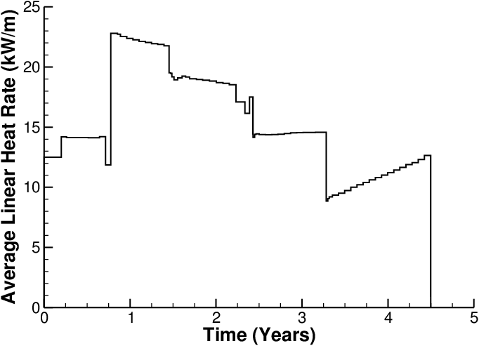
Figure 1: Power history for the TSQ002 fuel rod.
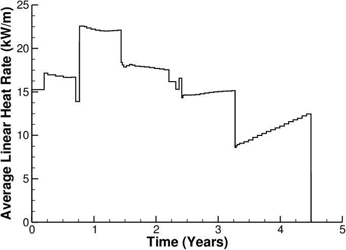
Figure 2: Power history for the TSQ022 fuel rod.
Model Description
Geometry and Mesh
A 2-dimensional axi-symmetric quadratic mesh was used to model the geometry for both rods. The fuel pellets were modeled using a single cylindrical fuel column, refered to as a smeared pellet mesh. Both meshes consisted of 1925 axial elements and 11 radial elements. The clad mesh for both rods consisted of 1931 axial elements and 4 radial elements.
Input files
The BISON input and all supporting files (power histories, axial power profile, fast neutron flux history, etc.) for this case are provided with the code distribution at bison/assessment/LWR/validation/US_PWR_16x16/analysis.
Material and Behavioral Models
The following material and behavioral models for UO fuel were used:
UO2Thermal - NFIR: NFIR model for temperature and burnup dependent thermal properties
ComputeFiniteStrainElasticStress: elastic mechanical behavior
ComputeIsotropicElasticityTensor: Constant values are used for the Young's modulus ( Pa) and Poisson ratio ()
UO2RelocationEigenstrain: relocation strains, relocation activation threshold power set to 5 kW/m
ComputeThermalExpansionEigenstrain: thermal expansion with a constant instanteous thermal expansion coefficient
UO2VolumetricSwellingEigenstrain : volumetric expansion due to solid and gaseous swelling
UO2Sifgrs: fission gas release model used with the gaseous swelling model
UO2VolumetricSwellingEigenstrain(Pastore et al., 2015)
For one particular simulation of the TSQ 002 case, the elastic stress material used to model the fuel mechanical behavior is replaced by a combination of a cracking material and a creep material model:
ComputeSmearedCrackingStress: represents cracking with an isotropic softening model
UO2CreepUpdate: mechanical creep and elastic deformation behavior for UO fuel as a function of temperature and fission rate
For the cladding material, a constant thermal conductivity of 16 W/m-K was used and both thermal and irradiation creep were considered using the Limback model (Limbäck and Andersson, 1996). The following material and thermal behavior models were used for the Zircaloy-4 cladding:
HeatConductionMaterial: Thermophysical material properties
ZryCreepLimbackHoppeUpdate and ZryElasticityTensor: mechanical creep and elastic deformation behavior for Zircaloy-4
ZryIrradiationGrowthEigenstrain: ESCORE model for volumetric swelling due to irradiation exposure
ZryThermalExpansionMATPROEigenstrain: thermal expansion of Zircaloy with the MATPRO model
Details and references for all of these models listed above can be found on the linked BISON documentation pages.
Results Comparison
The purpose of this series of experiments was to increase final fuel discharge burnup and to demonstrate improved fuel utilization through more effcient fuel management. The two rods of interest, for this study, are TSQ002 and TSQ022, which compare the difference between annular and solid pellets with the standard PWR fuel design (IAEA, 2008-2012). Experimental data is sparse as these are commercial rods irradiated in a commercial plant. The through life fuel centerline temperature and the through life rod internal pressure results were compared to other well know fuel performance codes. The data for these comparisons were digitized from the plots in the FUMEX-III Summary Report (IAEA, 2008-2012). The total fission gas release and the end of life final rod diameter calculations were compared to experimental data.
TSQ002
Temperature
As there is no experimental data to compare the fuel centerline temperature to, BISON results were compared to other well know fuel performance codes (IAEA, 2008-2012). As show in Figure 3, the BISON predictions for fuel centerline temperature compare well with the other codes. Note: The fuel centerline temperature was taken at a node near the axial mid-plane of the rod.
Fission Gas Release
The only fission gas release data available for this experiment is from post irradiation examination (PIE) puncture tests at the end of the fuel life. Figure 4 shows BISON's comparisons with the end of life experimental data.
Internal Rod Pressure
As there is no rod internal pressure data to compare to, BISON calculations are compared to other well known fuel performance codes (IAEA, 2008-2012). As shown in Figure 5, the BISON predictions of rod internal pressure compare well with the other codes.
Rod Diameter
The final rod diameter is an indication of how well the solid mechinics featured in BISON are predicting fuel swelling and clad creep. Figure 6 has the BISON to experimental comparisons for the end of life final rod diamter. The BISON predictions over estimate the end of life rod diameter, with a difference of appoximatly 0.02 mm. Results of the other fuel performance codes can be found in reference (IAEA, 2008-2012).
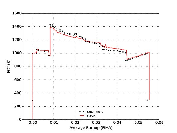
Figure 3: Fuel centerline temperature comparisons for rod TSQ002.
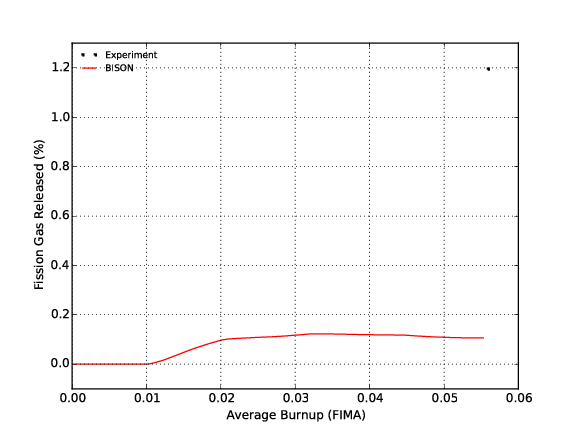
Figure 4: Fission gas release comparisons for rod TSQ002.
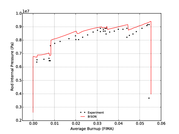
Figure 5: Through life code comparisons for the rod internal pressure for fuel rod TSQ002.
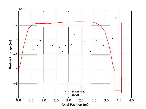
Figure 6: Final rod diameter comparisons for fuel rod TSQ002.
TSQ022
Temperature
As there is no experimental data to compare the fuel centerline temperature to, BISON results were compared to other well known fuel performance codes (IAEA, 2008-2012). As show in Figure 7, the BISON predictions for fuel centerline temperature compare well with the other codes. Note: The fuel centerline temperature was take at a node near the axial mid-plane of the rod.
Fission Gas Release
The measured fission gas released was 0.85%, BISON did not predict any fission gas release for this experiment.
Rod Internal Pressure
As there is no rod internal pressure data to compare to, BISON calculations are compared to other well known fuel performance codes (IAEA, 2008-2012). As shown in Figure 8, the BISON predictions for the rod internal pressure are lower than the other codes plotted. The lack of fission gas release in the BISON simulation could account for the lower pressure calculated.
Rod Diameter
The final rod diameter is an indication of how well the solid mechanics featured in BISON are predicting fuel swelling and clad creep. Figure 9 shows the BISON to experimental comparisons for the end of life final rod diamter. The BISON predictions over estimate the end of life rod diameter, with a difference of appoximatly 0.03 mm. Results of the other fuel performance codes can be found in reference (IAEA, 2008-2012).
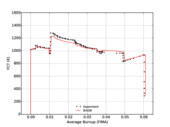
Figure 7: Fuel centerline temperature comparisons for rod TSQ022.
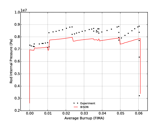
Figure 8: Through life code comparisons for the rod internal pressure for fuel rod TSQ022.

Figure 9: Final rod diameter comparisons for fuel rod TSQ022.
Discussion
Data for these two simulations, TSQ002 and TSQ022, where provided in a histogram format from the FUMEX-III database. A script was written at Idaho National Laboratory to convert this histogram style formatting in to a linear style format for BISON's PiecewiseLinear function call. This script can be found with the code distribution at bison/assessment/US_PWR_16x16/analysis. From the results shown above it is plain to see that BISON results differ from the other codes mainly in the end of life rod diameter. Pellet-cladding interactions are extremely complex and modeling them is not a trivial matter. The BISON code is constantly undergoing changes and revisions to rectify weaknesses and results will be revisited as new and improved features are made available.
References
- IAEA.
Improvement of Computer Codes Used for Fuel Behaviour Simulation (FUMEX-III): Report of a Coordinated Research Project 2008-2012.
Technical Report IAEA-TECDOC-1697, International Atomic Energy Agency, 2008-2012.[BibTeX]
- M. Limbäck and T. Andersson.
A model for analysis of the effect of final annealing on the in- and out-of-reactor creep behavior of zircaloy cladding.
In Zirconium in the Nuclear Industry: Eleventh International Symposium, ASTM STP 1295, 448–468. 1996.[BibTeX]
- G. Pastore, L.P. Swiler, J.D. Hales, S.R. Novascone, D.M. Perez, B.W. Spencer, L. Luzzi, P. Van Uffelen, and R.L. Williamson.
Uncertainty and sensitivity analysis of fission gas behavior in engineering-scale fuel modeling.
Journal of Nuclear Materials, 465:398–408, 2015.[BibTeX]