LOCA REBEKA
Overview
The REBEKA separate effects tests (Erbacher et al., 1982) (Markiewicz and Erbacher, 1988) (Erbacher et al., 1990) are temperature transient tests in steam performed on single PWR-size Zircaloy-4 tubes at a variety of internal pressures and heating rates. The purpose of the tests was to establish data of cladding ballooning and burst with reference to LOCA conditions. The single-rod tests from the REBEKA program have been simulated with BISON for validation of code's modeling capabilities to reproduce cladding ballooning and burst under LOCA conditions.
Test Description
Experiment
The cladding tubes had a fabricated inner/outer diameter of 9.30/10.75 mm, with a 325 mm heated length, and were heated indirectly by conduction heating from inside, using an electrically insulated heater rod. A stack of alumina annular pellets () was used to simulate the fuel column in a fuel elements. The diametral c1earance between the cladding inner diameter and the pellets outer diameter was 0.15 mm. The axial gap distance between the end plugs and alumina pellets stack was 15 mm. Considering this magnitude and the change in the axiallength of the tube, it can be said that these experiments were carried out under axially unconstrained conditions. The test parameters covered a range of 1 to 14 MPa for the internal rod (He) pressure and 1 to 30 K s for the heating rate. The test atmosphere was almost stagnant steam at atmospheric pressure and at a temperature of 473 K. The cladding temperatures were measured by thermocouples spot-welded on the outer surface of the cladding. More details on the experimental apparatus and conditions are given in (Erbacher et al., 1982) (Markiewicz and Erbacher, 1988) (Erbacher et al., 1990).
Model Description
Geometry and Mesh
The considered cases are modeled considering only the cladding, while the allumina pellets are taken into account imposing a proper tempeature boundary conditions at the cladding inner radius, which accounts for the heat transfer through the inner components. For simplicity, only the heated portion of the rods was simulated.
A 2-dimensional axisymmetric quadratic (Quad8 elements) mesh was used to model the geometry of the considered rods. In addition, to investigate inherently three-dimensional aspects, such as the effect of azimuthal temperature differences, 3D simulations were conducted emplying hexahedral elements (Hex20 elements).
Taking advantage of the symmetry of the problem, only the lower half of the heated cladding length was modelled in the 2D simulations. For the 3D simulations, a quarter of the cladding circumference was modelled.
Input files
The BISON input and all supporting files for these cases are provided with the code distribution at bison/assessment/LWR/validation/LOCA_REBEKA_cladding_burst_tests/analysis.
Material Models
The following material and behavioral models were used for the Zircaloy-4 cladding:
ZryThermal: Thermophysical material properties of Zircaloy.
ZryCreepLOCAUpdate and ZryElasticityTensor: Calculates the Erbacher secondary thermal creep under loss-of-coolant accident conditions
ZryThermalExpansionMATPROEigenstrain: Computes the thermal expansion of Zircaloy with the MATPRO model
ZrPhase: Calculates the relative amounts of the and material phases present as a function of time and temperature. The model is based on (Massih, 2009) (Massih and Jernkvist, 2009)
ZryOxidation: Model for waterside oxidation of Zircaloy, including oxidation in high temperature steam (Leistikow et al., 1983)
ZryCladdingFailure: Criterion for cladding failure due to burst, based on the calculated hoop stress and creep strain rate (Erbacher et al., 1982) (Marcello et al., 2014), and takes into account the effect of Zirconium phase transition and oxidation
Details and references for all of these models listed above can be found on the linked BISON documentation pages.
Boundary Conditions
The internal electric heating was simulated by a time-dependent Dirichlet temperature boundary condition applied to the tube inner wall and consistent with the experimental conditions. In particular, a parabolic temperature profile symmetric with respect to the tube mid-plane was considered, which results from the uniform axial power generation in the heater rod (Erbacher et al., 1990). To estimate the temperature variation over the heated length of the cladding, simplified calculations of axial heat conduction within the rod and convection to the outer steam atmosphere were performed, based on available information on materials and experimental conditions (Erbacher et al., 1982) (Markiewicz and Erbacher, 1988) (Erbacher et al., 1990). Pressure equal to the experimental value was applied at the tube inner wall.
Results
Using the 2D axisymmetric model, simulations were conducted of the REBEKA experiments with a heating rate of 1 K s, considering the full range of 1 to 14 MPa for the internal cladding pressure. As for the 3D model, only one case is here reported, in order to demonstrate BISON's ability to assess the impact of azimuthal temperature variations on cladding ballooning and burst.
2D simulations
The predictions of burst temperature at the various internal cladding pressures are compared to the available experimental data in Figure 1. The trend of increasing burst temperature with decreasing internal pressure is reproduced, and the quantitative accuracy of predictions is reasonable. Nevertheless, a moderate but systematic under-prediction is observed. Such discrepancies may be due to uncertainties inherent in the cladding mechanics, oxidation and phase transformation modelling, three-dimensional effects (azimuthal temperature differences) that cannot be captured by 2D modelling, as well as measurement uncertainties.
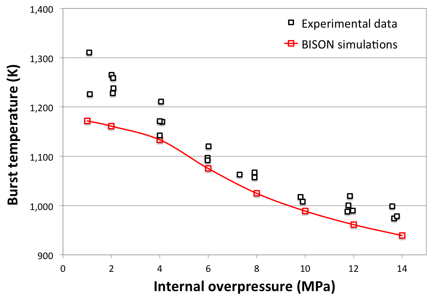
Figure 1: Comparison between BISON predictions and experimental data of cladding burst temperature for the simulations of the REBEKA tests with heating rate of 1 K s.
Figure 2 shows contour plots of temperature, creep strain magnitude, and locations where the local stress reached the limiting burst stress for the case with 10 MPa internal pressure; results are shown at the time of cladding burst. The creep strain magnitude (-) is defined as
(1)
where is the creep strain tensor. The cladding ballooning effect as reproduced by BISON is obvious. Cladding failure due to burst is predicted at a temperature of about 993 K and a creep strain magnitude of about 1.1, which reasonably conform to experimental observations (Erbacher et al., 1982) (Erbacher et al., 1990). The burst stress is first reached in the cladding mid-section of the cladding, which is characterized by the largest strain and hence by the highest thinning. The time evolution of the hoop stress and burst stress in the cladding mid-section in proximity of time of burst are plotted in Figure 3. The corresponding hoop strain is also shown. The stress increases under the effect of the constant inner pressure as the cladding wall thins due to the large creep strain. The burst stress decreases over time due to increasing temperature and progressive cladding oxidation (and in general also due to phase transformation, not observed at the temperatures reached in this specific case). The calculated time evolution of the cladding hoop strain is consistent with the experimental observations (Erbacher et al., 1990).
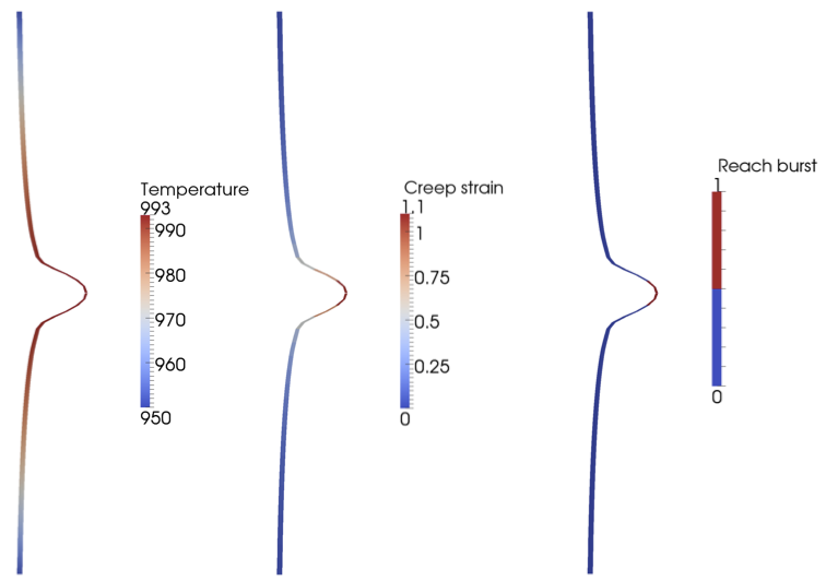
Figure 2: Contour plots for the BISON 2D simulation of the REBEKA test with 10 MPa internal pressure at the time of cladding burst. The results for the lower half of the heated cladding are mirrored to obtain a full-length view. The plots are magnified 4x in the radial direction for visualization.
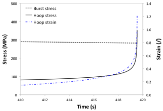
Figure 3: Time evolution of burst stress, hoop stress, and hoop strain at the cladding mid-section in proximity of time of burst. The results refer to the BISON simulation of the REBEKA test with 10 MPa internal pressure.
3D simulation
In addition to above mentioned boundary conditions applied to the 2D simulations, in the 3D simulation an azimuthal temperature gradient was applied. A maximum azimuthal temperature variation of 30 K was considered, in conformity with the experimental indications from thermocouple measurements (Markiewicz and Erbacher, 1988). The results are presented for the exemplifying case of 10 MPa internal pressure at the time of cladding burst. Figure 4 shows contour plots of temperature, creep strain magnitude, and locations where the local stress reached the limiting burst stress. The 3D simulation reproduces the non-uniform cladding ballooning and a localized burst on the hottest side of the cladding, which is consistent with experimental observations (Markiewicz and Erbacher, 1988). Note that the predicted burst temperature is higher (by about 10 K) than for the corresponding 2D simulation, thus indicating that capturing 3D aspects such as the effect of azimuthal temperature differences is of importance for fuel analysis during accidents.
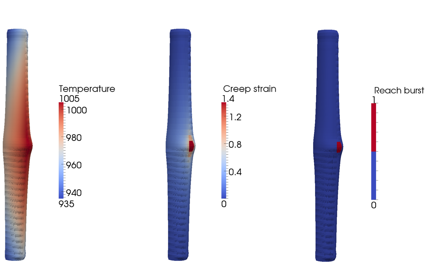
Figure 4: Contour plots for the BISON 3D simulation of the REBEKA test with 10 MPa internal pressure at the time of cladding burst. The results for the lower quarter of the heated cladding are mirrored to obtain a full-length, half circumference view. The plots are magnified 3x in the radial direction for visualization. The blur zones are due to the adopted visualization tool.
References
- F. J. Erbacher, H. J. Neitzel, H. Rosinger, H. Schmidt, and K. Wiehr.
Burst criterion of Zircaloy fuel claddings in a loss-of-coolant accident.
In Zirconium in the Nuclear Industry, Fifth Conference, ASTM STP 754, D.G. Franklin Ed., 271–283. American Society for Testing and Materials, 1982.[BibTeX]
- F.J. Erbacher, H.J. Neitzel, and K. Wiehr.
Technical Report KfK 4781, Kernforschungszentrum, Karlsruhe, 1990.[BibTeX]
- S. Leistikow, G. Schanz, H. v. Berg, and A.E. Aly.
Comprehensive presentation of extended Zircaloy-4/steam oxidation results 600-1600 C.
In CSNI/IAEA specialists meeting on water reactor fuel safety and fission product release in off-normal and accident conditions. Riso Nat. Lab., Denmark, 1983.[BibTeX]
- V. Di Marcello, A. Schubert, J. van de Laar, and P. Van Uffelen.
The TRANSURANUS mechanical model for large strain analysis.
Nuclear Engineering and Design, 276:19–29, 2014.[BibTeX]
- M. E. Markiewicz and F.J. Erbacher.
Experiments on ballooning in pressurized and transiently heated Zircaloy-4 tubes.
Technical Report KfK 4343, Kernforschungszentrum Karlsruhe GmbH (Germany, Kernforschungszentrum Karlsruhe, Germany, 1988.[BibTeX]
- A.R. Massih.
Transformation kinetics of zirconium alloys under non-isothermal conditions.
Journal of Nuclear Materials, 384:330–335, 2009.[BibTeX]
- Ali R Massih and Lars Olof Jernkvist.
Transformation kinetics of alloys under non-isothermal conditions.
Modelling and Simulation in Materials Science and Engineering, 17(5):055002, 2009.[BibTeX]