IFA-716.1 Rod 1 and Rod 6
Overview
The IFA-716.1 test (Tverberg, 2014; Baurens, 2016) was performed at the Halden Reactor Project with the aim to study the fuel performance of Cr-doped UO and large grain UO with respect to fission gas release (FGR), swelling and densification. The very high temperature region was already covered by the high initial rating test IFA-677.1 (Jos̆ek, 2008), therefore, IFA-716.1 was operated at lower power such that the fuel temperature is below the FGR threshold during the initial power cycles. The test rig contained six rods supplied by AREVA and ULBA. Two of the rods contained UO fuel doped with CrO. All rods were instrumented with pressure transducers, fuel centreline thermocouples on the upper end and fuel stack elongation detectors, in addition to a cladding extensometer for one of the rods. The test was loaded in the Halden reactor in January 2010 and completed six cycles of irradiation under Halden Boiling Water Reactor (HBWR) conditions in May 2015, achieving a rig average burnup of 31.8 MWd/kgOX.
Rod 1 and Rod 6 from the IFA-716.1 test are included in the BISON assessment database. This report presents the BISON simulation and comparisons of the predictions to the available experimental data of fuel centerline temperature, fission gas release, rod inner pressure and fuel stack elongation. These results contribute to the assessment of BISON for the analysis of CrO-doped UO fueled light water reactor (LWR) rods.
Test Description
The IFA-716.1 rig contained a single cluster of six rods with an active fuel length of about 400 mm and initial enrichment of about 4.9%.
IFA-716.1 Rod 1 contained doped UO fuel with 1580 ppm CrO, and Rod 6 contained doped UO fuel with 1050 ppm CrO. The doped fuel has larger grain size compared to standard UO fuel. The main characteristics of Rod 1 and Rod 6 are summarized in Table 1.
Table 1: Fabrication characteristics of IFA-716.1 Rod 1 and Rod 6
| Rod 1 | Rod 6 | Unit | |
|---|---|---|---|
| Cladding material | Zircaloy-4 | Zircaloy-4 | |
| Fuel material | Doped UO | Doped UO | |
| Fill gas | He | He | |
| Total active fuel stack length | 399.5 | 399.3 | mm |
| Pellet inner diameter (drilled sections) | 1.8 | 1.8 | mm |
| Pellet outer diameter | 9.12 | 9.12 | mm |
| Diametral gap | 180 | 180 | m |
| Cladding thickness | 0.725 | 0.725 | mm |
| Cladding outer diameter | 10.75 | 10.75 | mm |
| Free volume | 5.80 | 6.0 | cm |
| Fill gas pressure | 1.0 | 1.0 | MPa |
| Fuel CrO content | 1580 | 1050 | ppm |
| Fuel U-235 enrichment | 4.90 | 4.89 | |
| Initial fuel density | 10500 | 10530 | kg/m |
| Fuel average grain radius | 35 | 29.5 | m |
Operating Conditions and Irradiation History
The test rig was operated under standard HBWR conditions, i.e., natural circulation at a coolant (moderator) pressure of 34 bar and saturation temperature of 235C, experiencing 842 full power days of accumulated operation. The final average assembly burnup is 31.8 MWd/kgOX (Baurens, 2016). The average linear heat rate (LHR) were kept below the FGR threshold during the first six irradiation cycles, and an assembly average burnup of 17 MWd/kgOX was reached by the end of this period. Later, the LHR was elevated slowly to bring the fuel temperature above the FGR threshold to study the FGR performance. The power level was later kept close to the FGR threshold.
Model Description
Geometry and Mesh
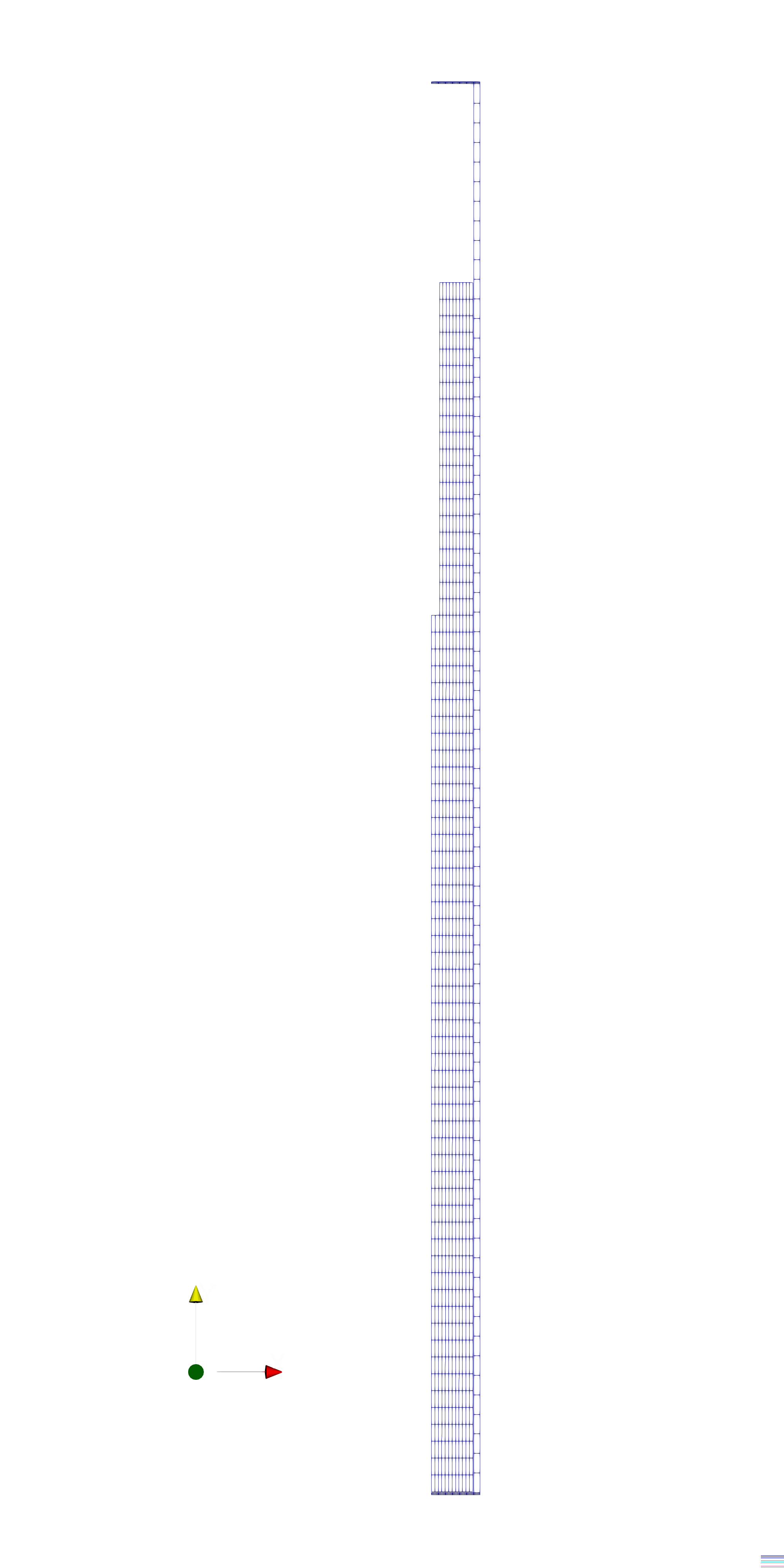
Figure 1: Mesh for IFA 716.1 Rod 1

Figure 2: Mesh for IFA 716.1 Rod 6
A 2D axisymmetric geometrical model and linear elements were used for the mesh. For simplicity, the pellet stack was modeled as a single continuous fuel column. The thermocouple is placed close to the bottom of the top drilled fuel section. Figure 1 and Figure 2 show a scaled view of the mesh for Rod 1 and Rod 6.
The plenum length was adjusted so that the internal volume of the rod (gap, drilled sections, and plenum) matched the value for the free volume from the Halden data (see Table 1).
Input files
The BISON input and all supporting files are provided with the code distribution at bison/assessment/LWR/validation/IFA_716/analysis.
To avoid code duplication, the input files are built as follows: A base input file contains characteristics common to the entire assessment case. A second base input file contains characteristics common to non-mortar and mortar run-types. Specific model, numerical, and configuration parameters for non-mortar and mortar run-types are listed in .params and .i files, respectively, as well as locations to irradiation history data. The base input files require the information contained in the .params or .i files and cannot run on its own. To run a specific non-mortar run-type assessment case, the input file can be created by listing the rod pair base file and the desired parameters, such as, for IFA_716_rod1: ../IFA_716_Base.i ../IFA_716_Base_No_Mortar IFA_716_rod1.params To run a specific mortar run-type assessment case, simply run the IFA_716_rod#_mortar.i file.
Material and Behavioral Models
The following material and behavioral models for UO fuel were used:
UO2Thermal - Halden: Halden model for temperature and burnup dependent thermal properties
UO2CreepUpdate: MATPRO model for fuel creep mechanical behavior
UO2ElasticityTensor: a elastic mechanical behavior calculator
UO2RelocationEigenstrain: relocation strains, relocation activation threshold power set to 5 kW/m
UO2ThermalExpansionMATPROEigenstrain: MATPRO model for fuel thermal expansion
UO2VolumetricSwellingEigenstrain: volumetric expansion due to solid and gaseous swelling
UO2Sifgrs: fission gas release model with the combined gaseous swelling model
UO2VolumetricSwellingEigenstrain(Pastore et al., 2015)
In addition, the following settings were adopted that are specific to CrO-doped UO fuel analysis:
Specific option for the lattice diffusion coefficient of fission gas atoms in the SIFGRS fission gas release and swelling model. The diffusion coefficient for CrO-doped UO is derived from the atomistic simulation developed at Los Alamos National Laboratory (LANL) (Cooper et al., 2021). This correction accounts for the increased diffusivity in CrO-doped UO relative to standard UO. This is associated with a higher uranium vacancy concentration in doped fuel.
CrO-doped UO is characterized by a larger grain size than standard UO. In contrast to the enhanced diffusivity, the larger grain radius tends to reduce fission gas release due to the associated larger intra-granular diffusion distance for gas atoms to travel before reaching the grain boundaries. The reported average grain radius for IFA-716.1 is 35m for Rod 1 and 29.5m for Rod 6 (Tverberg, 2014; Baurens, 2016). Accordingly, this value has been set for the fission gas model, which in turn utilizes it in the fission gas atom diffusion calculation. The grain radius is used in the fuel creep model as well.
A total densification in the MATPRO densification model of 0.15%. This is consistent with the experimental indications (Tverberg, 2014; Baurens, 2016) and with the lower densification expected in CrO-doped UO relative to standard UO.
The following material and behavioral models were used for the Zircaloy-4 cladding:
ZryThermal: thermal properties of Zircaloy-4
ZryCreepLimbackHoppeUpdate and ZryElasticityTensor: mechanical creep and elastic deformation behavior for Zircaloy-4
ZryIrradiationGrowthEigenstrain: ESCORE model volumetric swelling due to irradiation exposure
ZryThermalExpansionMATPROEigenstrain: thermal expansion of Zircaloy with the MATPRO model
ZryOxidation: EPRI/KWU/C-E model for the waterside oxidation of the Zircaloy cladding
Details and references for all of these models listed above can be found on the linked BISON documentation pages.
Boundary and Operating Conditions
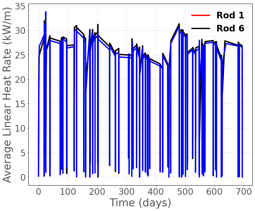
Figure 3: Average LHR history used as input for the simulation of IFA-716.1 Rod 1 and IFA-716 Rod 6. The Halden raw data were condensed using the Fuel Rod Analysis ToolBox (Lassmann et al., 2015).
LHR history for Rod 1 and Rod 6 are illustrated in Figure 3.
The thermal boundary conditions at the cladding outer surface were determined using BISON's internal coolant channel model. The coolant inlet temperature history was determined from the Halden raw data and supplied to BISON as a time-dependent input. Coolant flow conditions were taken from OECDHRP (2005). The Jens-Lottes heat transfer correlation, which is recommended for Halden HBWR conditions, was applied.
Contact Models
Mortar-based contact model have been observed with higher computational efficiency and robustness compared to conventional nodal-face contact (frictionless contact and augmented Lagrange contact). For the Halden IFA-716.1 validation cases, using the mortar-based frictional contact saves up to 25% of the total computational time compared to using the augmented Lagrangian or frictionless contact model. Therefore, separate input files are provided for mortar-based contact approach and frictionless contact under bison/assessment/LWR/validation/IFA_716/analysis/.
Case Setup
Two case setups are provided as shown in Table 2. The base case relies on reported values in Tverberg (2014) and Baurens (2016) as well as default model parameters in BISON for the missing information. Although Tverberg (2014) and Baurens (2016) indicate small densifications (0.1% to 0.2%) in general for the doped fuel, exact values of fuel densification were not specified for each rod. Therefore, an average value of indications (0.15%) is used. Under the Sifgrs FGR model, a best estimation of the diffusion coefficient (doping_type=1, cr_doped_option=5) is used. Based on the above setup, a systematic overestimation of fuel elongation prediction and underestimation of rod inner pressure are observed right from the beginning of life. Given that the aforementioned parameters can be associated with relatively large uncertainty, a corrected setup is provided, with slightly higher filled pressure, default fuel densification in BISON, and elevated stress-free temperature for fuel thermal expansion. An upper limit of the diffusion coefficient (doping_type=1, cr_doped_option=5) is also modeled in the corrected case to compensate for the underestimation of fuel temperature.
Table 2: Case setups for IFA-716.1 Rod 1 and Rod 6
| BISON | BISON-corrected | Unit | |
|---|---|---|---|
| Rod filled pressure | 10 (Baurens, 2016) | 11 | bar |
| Fuel total densification | 0.0015 (inferred from Baurens (2016)) | 0.01 (BISON default) | - |
| Fuel thermal expansion stress-free temperature | 293 | 350 | K |
| FGR diffusion coefficient model | best estimate | upper limit | - |
Results Comparison
In this section, we show comparisons of BISON predictions to experimental data for IFA-716 Rod 1 and Rod 6.
Fuel Centerline Temperature
The calculated fuel centerline temperature at the location of the upper fuel thermocouple for IFA-716.1 Rod 1 and Rod 6 as a function of the irradiation time are shown in Figure 4 and Figure 5, and compared to the on-line measured data. An underprediction of the measured temperature of up to 150 K is observed throughout the irradiation for both rods using the base case setup. Such discrepancy arises from overestimation of fuel thermal expansion therefore underestimated gap thickness, as well as too small fuel densification. With the corrected case setup, underestimation of the fuel temperature is only 100 K for the first three cycles of irradiation, and matches well the the measured data for the last three cycles of irradiation, consistent with what have been observed for IFA-677.1.
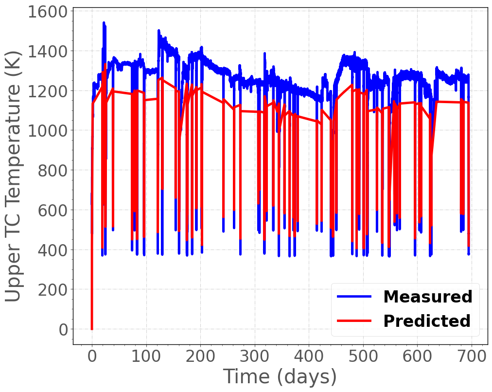
Figure 4: Comparison of predicted and measured fuel centerline temperature histories at the upper thermocouple location for IFA-716.1 Rod 1.
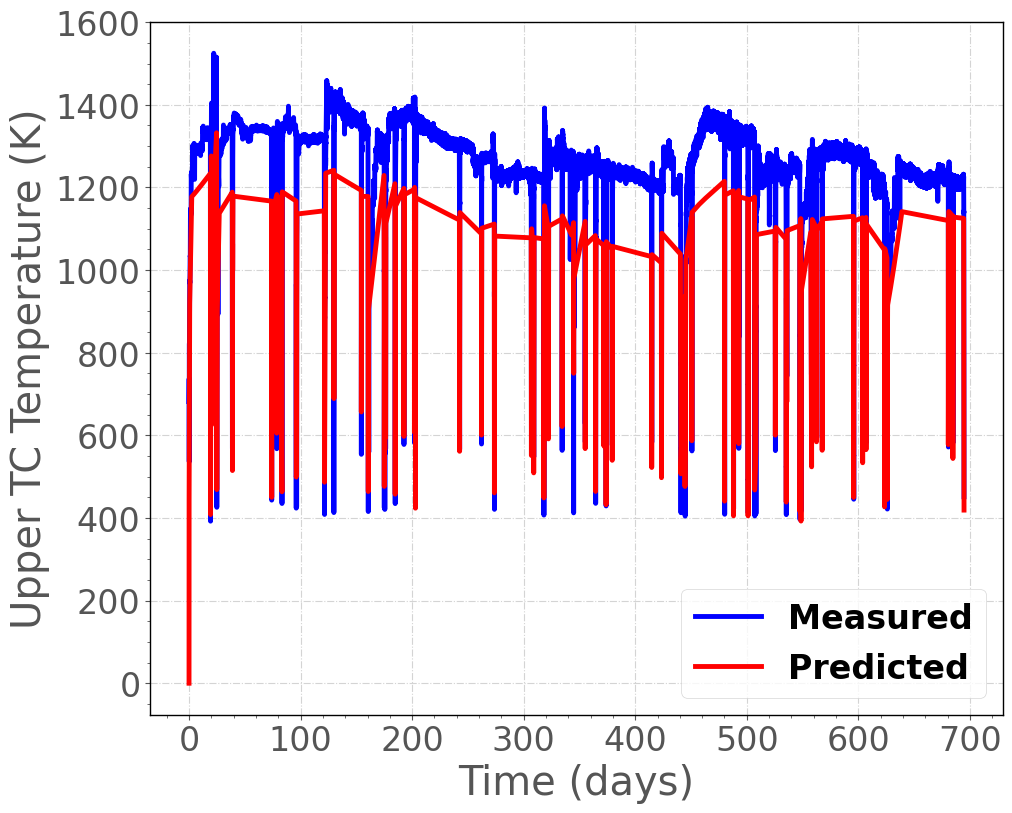
Figure 5: Comparison of predicted and measured fuel centerline temperature histories at the upper thermocouple location for IFA-716.1 Rod 6.
Fission Gas Release
The calculated fission gas release as a function of rod average burnup are shown in Figure 6 and Figure 7 along with the measured data (which are inferred from the inner rod pressure on-line measurement). With both setups, BISON predicts an earlier FGR onset than the on-line measurement, and the estimated FGR is lower than the measured data. With the base case setup, FGR is underestimated by 4% primarily due to underestimated fuel temperature, as FGR is temperature-sensitive. With the corrected setup, discrepancy between the measured and predicted FGR becomes much smaller (1.5%), which is more acceptable considering the relatively large inherent uncertainty related with FGR predictions (Pastore et al., 2015). It is also worth pointing out that the measured FGR is derived from the change of rod inner pressure, while the pressure sensor was reported with failure after 625 full power days ( 26 MWd/kgU) for Rod 1. Therefore, measured FGR after 625 full power days should not be used for the purpose of validation for Rod 1.
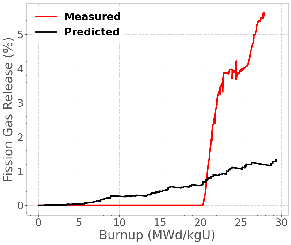
Figure 6: Comparison of predicted and measured fission gas release as a function of rod average burnup for IFA-716.1 Rod 1.
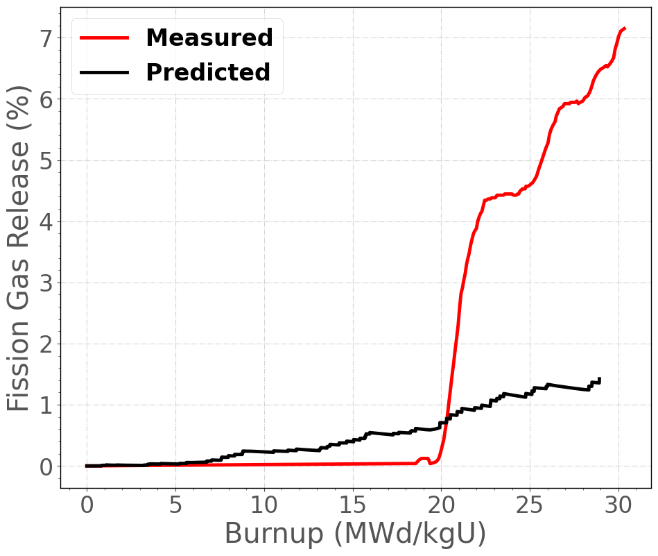
Figure 7: Comparison of predicted and measured fission gas release as a function of rod average burnup for IFA-716.1 Rod 6.
Rod internal pressure
In Figure 8 and Figure 9, the time evolution of rod inner pressure calculated by BISON are compared to the measured data from the pressure transducers in IFA-716.1 Rod 1 and Rod 6. With the base case setup, the rod internal pressure is underestimated by 0.15 MPa for the first three irradiation cycles. With the corrected setup, the rod pressure estimation matches better with the measured data for the first three cycles, and the discrepancy exaggerates for later cycles. As previously pointed out, the pressure transducer in Rod 1 failed during the last cycle, causing the sharp increase of the measured data towards the end of life. Underestimation of the rod internal pressure in the last three cycles is most likely due to underestimated fuel elongation, as will be shown in Figure 10 and Figure 11.
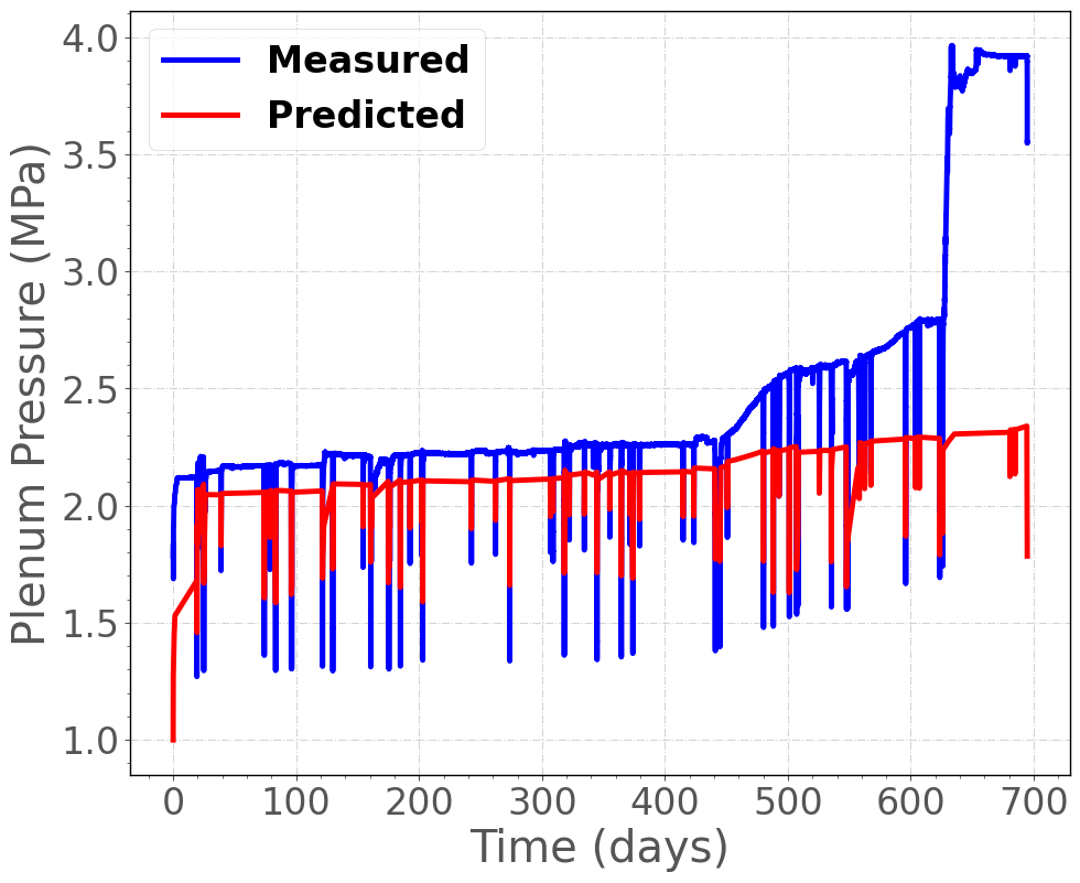
Figure 8: Comparison of predicted and measured inner rod pressure histories for IFA-716.1 Rod 1.
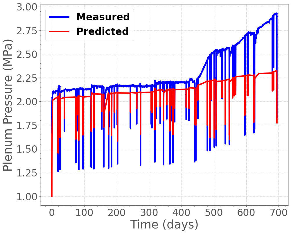
Figure 9: Comparison of predicted and measured inner rod pressure histories for IFA-716.1 Rod 6.
Fuel stack elongation
The calculated fuel stack elongation history is compared to the experimental data from the fuel elongation detector for IFA-716.1 Rod 1 in Figure 10 and IFA-716.1 Rod 6 in Figure 11. Malfunctioning of the elongation detector was reported for both Rod 1 and Rod 6 during the later cycles, causing the flat lines towards the end of life. With the base case setup, a systematic overprediction of the fuel elongation rate over time is observed in the BISON calculation. With the corrected setup, the simulated fuel elongation matches well with measured data for the initial cycles, but tends to be greater than measured data during later cycles.
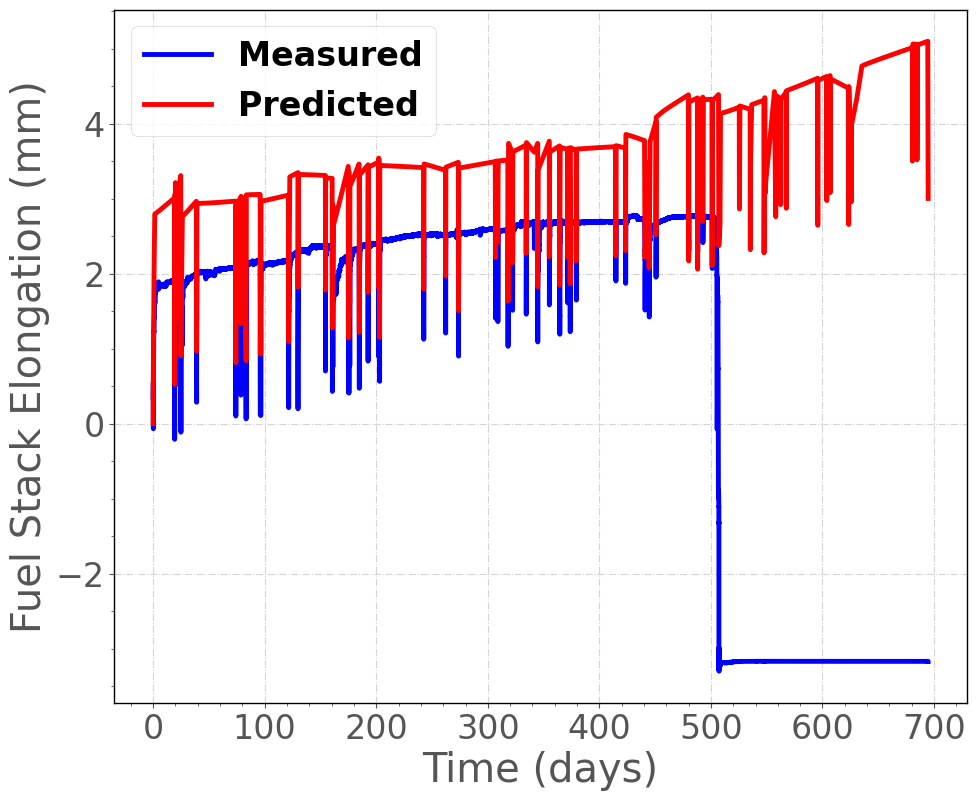
Figure 10: Comparison of predicted and measured fuel stack elongation histories for IFA-716.1 Rod 1. Note that the experimental data for the last two cycles is believed to be erroneous (Baurens, 2016).
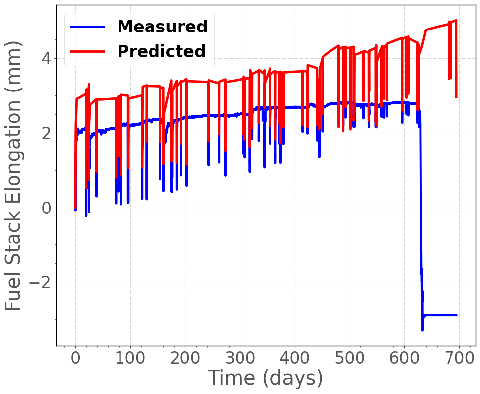
Figure 11: Comparison of predicted and measured fuel stack elongation histories for IFA-716.1 Rod 6. Note that the experimental data for the last cycle is believed to be erroneous (Baurens, 2016).
Conclusion
Further investigation of modeling fuel dimensional changes for Cr-doped UO in BISON is required, such as fuel densification, thermal expansion, and swelling behavior. Further investigation on the interpretation of the Halden data is also necessary for the purpose of code validation and model development.
References
- B Baurens.
In-pile results from the fission gas release mechanisms study in ifa-716 after final unloading.
Technical Report HWR-1161, OECD Halden Reactor Project, April 2016.[BibTeX]
- M. W. D. Cooper, G. Pastore, Y. Che, C. Matthews, A. Forslund, C. R. Stanek, K. Shirvan, T. Tverberg, K. A. Gamble, B. Mays, and others.
Fission gas diffusion and release for cr2o3-doped uo2: from the atomic to the engineering scale.
Journal of Nuclear Materials, 545:152590, 2021.[BibTeX]
- R. Jo\u sek.
The High Initial Rating Test IFA-677: Final Report on In-Pile Results.
Technical Report HWR-872, OECD Halden Reactor Project, April 2008.[BibTeX]
- K. Lassmann, A. Schubert, J. van de Laar, and P. Van Uffelen.
The 'Fuel Rod Analysis ToolBox': a general program for preparing the input of a fuel rod performance code.
Annals of Nuclear Energy, 81:332–335, 2015.[BibTeX]
- OECDHRP.
Data Sheet / IFA-677.1.
Technical Report QA-F-702, OECD Halden Reactor Project, 2005.[BibTeX]
- G. Pastore, L.P. Swiler, J.D. Hales, S.R. Novascone, D.M. Perez, B.W. Spencer, L. Luzzi, P. Van Uffelen, and R.L. Williamson.
Uncertainty and sensitivity analysis of fission gas behavior in engineering-scale fuel modeling.
Journal of Nuclear Materials, 465:398–408, 2015.[BibTeX]
- T Tverberg.
Update on the in-pile results from the fission gas release mechanisms study in ifa-716.
Technical Report HWR-1090, OECD Halden Reactor Project, September 2014.[BibTeX]