IFA-677.1 Rods 1 and 5
Overview
The High Initial Rating Test IFA-677.1 (Jos̆ek, 2008; Jenssen, 2010) was performed at the Halden Reactor Project with the aim to investigate the performance of modern fuels subjected to high initial rating with respect to thermal behavior, dimensional changes (densification and swelling), fission gas release and PCMI. The test rig contained six rods supplied by Westinghouse, Framatome ANP and GNF. Two of the rods contained UO fuel doped with CrO and AlO. All rods were instrumented with pressure transducers, fuel centreline thermocouples in both ends and fuel stack elongation detectors, in addition to a cladding extensometer for one of the rods. The test was loaded in the Halden reactor in December 2004 and completed six cycles of irradiation under Halden Boiling Water Reactor (HBWR) conditions in September 2007, achieving a rig average burnup of 26.3 MWd/kgOX.
Rods 1 and 5 from the IFA-677.1 test are included in the BISON assessment database at this time. This report presents the BISON simulation and comparisons of the predictions to the available experimental data of fuel centerline temperature, fission gas release, rod inner pressure and fuel stack elongation. These results contribute to the assessment of BISON for the analysis of Cr O-doped UO fueled LWR rods.
Test Description
The IFA-677.1 rig contained a single cluster of six rods with an active fuel length of about 400 mm and initial enrichment of about 4.95%.
IFA-677.1 Rod 1 contained doped UO fuel with 900 ppm CrO and 200 ppm AlO. Rod 5 contained doped UO fuel with 500 ppm CrO and 200 ppm AlO. The doped fuel has both higher density and larger grain size than standard UO. The main characteristics of Rods 1 and 5 are summarized in Table 1.
Table 1: Fabrication characteristics of IFA-677.1 Rod 1 and 5
| Rod 1 | Rod 5 | Unit | |
|---|---|---|---|
| Cladding material | Zircaloy-4 | Zircaloy-4 | |
| Fuel material | UO with additives | UO with additives | |
| Fill gas | He | He | |
| Total rod length | 456.0 | 459.5 | mm |
| Total active fuel stack length | 398.6 | 403.5 | mm |
| Drilled active section length (top) | 109.2 | 111.0 | mm |
| Drilled active section length (bottom) | 109.7 | 111.1 | mm |
| Pellet inner diameter (drilled sections) | 1.8 | 1.8 | mm |
| Pellet outer diameter | 9.13 | 9.13 | mm |
| Diametral gap | 170 | 170 | m |
| Cladding thickness | 0.725 | 0.725 | mm |
| Cladding outer diameter | 10.75 | 10.75 | mm |
| Free volume | 5.34 | 5.26 | cm |
| Fill gas pressure | 1.35 | 1.35 | MPa |
| Fuel CrO content | 900 | 500 | ppm |
| Fuel AlO content | 200 | 200 | ppm |
| Fuel U-235 enrichment | 4.94 | 4.94 | |
| Initial fuel density | 10690 | 10700 | kg/m |
| Fuel average grain radius | 28 | 22.5 | m |
Operating Conditions and Irradiation History
The test rig was operated under standard HBWR conditions, i.e., natural circulation at a coolant (moderator) pressure of 34 bar and saturation temperature of 235 C. The test completed six cycles of irradiation. The discharge rod average burnup for Rod 1 was 26.3 MWd/kgOX (Jos̆ek, 2008). Average linear heat rates (LHR) for the rods in IFA-677 were in the range of 30-45 kW/m, i.e., high power. For the rods in IFA-677.1, during the first irradiation cycle the LHR was kept at 42-46 kW/m. Lower power of 33-42 kW/m was experienced by the rods during the second and third cycles. During the fourth cycle the LHR was raised again from 35 to 43 kW/m at the beginning of the cycle. In the fifth cycle, the rod LHR first increased to 40kW/m, then declined to 30 kW/m at the end of the cycle. During the sixth cycle the LHR was again increased to 45 kW/m and then decreased to 35 kW/m.
Model Description
Geometry and Mesh
A 2D axisymmetric geometrical model and linear elements were used for the mesh. For simplicity, the pellet stack was modeled as a single continuous fuel column. The thermocouple holes at the top and bottom of the fuel column were included. Figure Figure 1 shows a scaled view of the mesh for Rod 1.
The plenum length was adjusted so that the internal volume of the rod (gap, drilled sections, and plenum) matched the value for the free volume from the Halden data (Table Table 1).
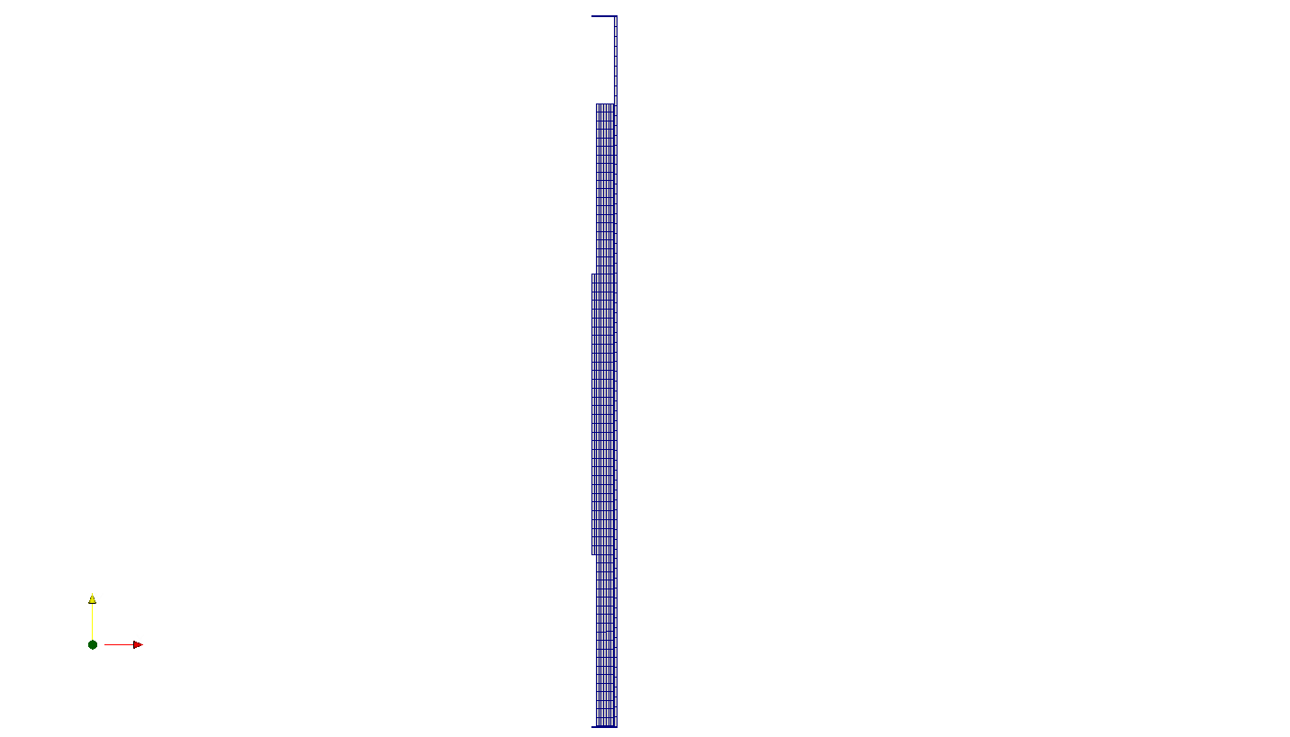
Figure 1: Mesh for IFA 677.1 Rod 1
Input files
The BISON input and all supporting files are provided with the code distribution at bison/assessment/LWR/validation/IFA_677/analysis.
To avoid code duplication, the input files are built as follows: A base input file contains characteristics common to the entire assessment case. Specific model, numerical, and configuration parameters are listed in .params files, as well as locations to irradiation history data. The base input files require the information contained in the .params files and cannot run on its own. To run a specific assessment case, the input file can be created by listing the rod pair base file and the desired parameters, such as, for IFA_677_rod1: IFA_677_Base.i IFA_677_rod1.params
Material and Behavioral Models
The following material and behavioral models for UO fuel were used:
UO2Thermal - HALDEN: HALDEN model for temperature and burnup dependent thermal properties
UO2CreepUpdate: MATPRO model for fuel creep mechanical behavior. This is coupled to a smeared cracking model ComputeSmearedCrackingStress
UO2ElasticityTensor: isotropic elastic mechanical behavior.
UO2RelocationEigenstrain: relocation strains, relocation activation threshold power set to 5 kW/m
UO2ThermalExpansionMATPROEigenstrain: MATPRO model for fuel thermal expansion
UO2VolumetricSwellingEigenstrain: volumetric expansion due to solid and gaseous swelling
UO2Sifgrs: fission gas release model with the combined gaseous swelling model
UO2VolumetricSwellingEigenstrain(Pastore et al., 2015)
In addition, the following settings were adopted that are specific to CrO-doped UO fuel analysis:
Specific option for the lattice diffusion coefficient of fission gas atoms in the SIFGRS fission gas release and swelling model. The diffusion coefficient for UO is scaled with a temperature-dependent correction developed at Los Alamos National Laboratory (LANL) (Cooper et al., 2018). This correction accounts for the increased diffusivity in CrO-doped UO relative to standard UO. This is associated with a higher uranium vacancy concentration in doped fuel.
Cr O-doped UO is characterized by a larger grain size than standard UO. In contrast to the enhanced diffusivity, the larger grain radius tends to reduce fission gas release due to the associated larger intra-granular diffusion distance for gas atoms to travel before reaching the grain boundaries. The reported average grain radius for IFA-677.1 Rod 1 is 28m and Rod 5 is 22.5 m (Jos̆ek, 2008; Jenssen, 2010). Accordingly, this value has been set for the fission gas model, which in turn utilizes it in the fission gas atom diffusion calculation. The grain radius is used in the fuel creep model as well.
A total densification in the MATPRO densification model of 0.09%. This is consistent with the experimental indications (Jos̆ek, 2008; Jenssen, 2010) and with the lower densification expected in CrO-doped UO relative to standard UO.
The following material and behavioral models were used for the Zircaloy-4 cladding:
ZryThermal: isotropic thermal properties for Zircaloy
ZryCreepLimbackHoppeUpdate and ZryElasticityTensor: mechanical creep and elastic deformation behavior for Zircaloy-4
ZryIrradiationGrowthEigenstrain: ESCORE model volumetric swelling due to irradiation exposure
ZryThermalExpansionMATPROEigenstrain: thermal expansion of Zircaloy with the MATPRO model
ZryOxidation: EPRI/KWU/C-E model for the waterside oxidation of the Zircaloy cladding
Details and references for all of these models listed above can be found on the linked BISON documentation pages.
Boundary and Operating Conditions
The average linear heat rate (LHR) history for Rods 1 and 5 are illustrated in Figure 2.

Figure 2: Average linear heat rate history used as input for the simulation of IFA-677.1 Rod 1 and 5. The Halden raw data were condensed using the Fuel Rod Analysis ToolBox (Lassmann et al., 2015).
The power histories provided in Figure 2 are as received from the Halden data. A modification to the average linear heat rate and is required based upon information contained within (Weisenak, 2019). An approximate 2% reduction in the average linear power is applied to the power after a burnup of approximately 14.5 MWd/kgU and lasting until the end of the irradiation due to changes in the reactor environment near the IFA-667.1 rig. A second change was also applied to the axial profile including a reduction in power at the bottom (1.5%) and top (3.5%) power nodes, a slight increase at the upper and lower thermocouple locations (2.6%), and a larger increase at the middle power node (4.3%).
The thermal boundary conditions at the cladding outer surface were determined using BISON's internal coolant channel model. The coolant inlet temperature history was determined from the Halden raw data and supplied to BISON as a time-dependent input. Coolant flow conditions were taken from (OECDHRP, 2005). The Jens-Lottes heat transfer correlation, which is recommended for Halden HBWR conditions, was applied.
Results Comparison
In this section, we show comparisons of BISON predictions to experimental data for IFA-677 Rods 1 and 5.
Fuel Centerline Temperature
The calculated fuel centerline temperature at the location of the upper fuel thermocouple for IFA-677.1 Rod 1 as a function of the irradiation time is shown in Figure 3 and compared to the on-line measured data. An underprediction of the measured temperature of up to 100 K is observed for the first 3 cycles of irradiation. Such a discrepancy corresponds to a relative error of 7%, which is within the uncertainties due to the measured power used as input for the calculation. The BISON calculation matches the experimental data well for the fourth and fifth cycle of irradiation. For the sixth cycle, an overprediction of 100 K is observed. The difference in the behavior between the early and late periods of the irradiation may be associated with gap closure approximately at the beginning of the fourth cycle. Gap closure corresponds to the introduction of the solid-solid contact mode for the fuel-to-cladding heat transfer, which corresponds to additional complexity for the modeling of the gap heat transfer.
The calculated and measured fuel centerline temperatures at the lower thermocouple location are shown in Figure 4. This additional comparison confirms the behavior observed for the temperature prediction at the upper thermocouple location, with an underprediction of up to 100 K for the first three irradiation cycles, a very accurate prediction during the first and fourth cycles, and an overprediction during the last cycle.
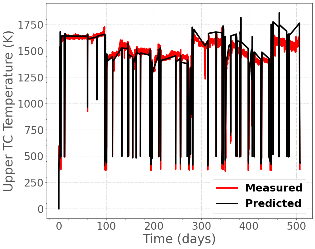
Figure 3: Comparison of predicted and measured fuel centerline temperature histories at the upper thermocouple location for IFA-677.1 Rod 1.
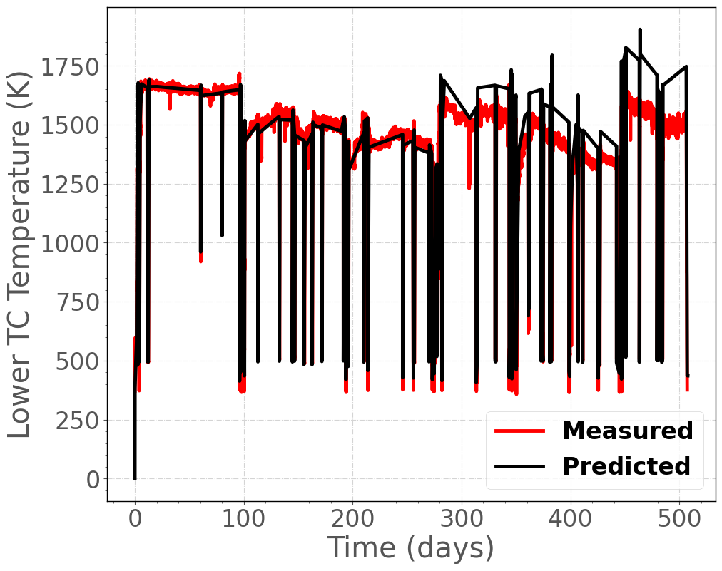
Figure 4: Comparison of predicted and measured fuel centerline temperature histories at the lower thermocouple location for IFA-677.1 Rod 1.
Similar results are observed for Rod 5 at both the upper and lower thermocouples as shown in Figure 5 and Figure 6.
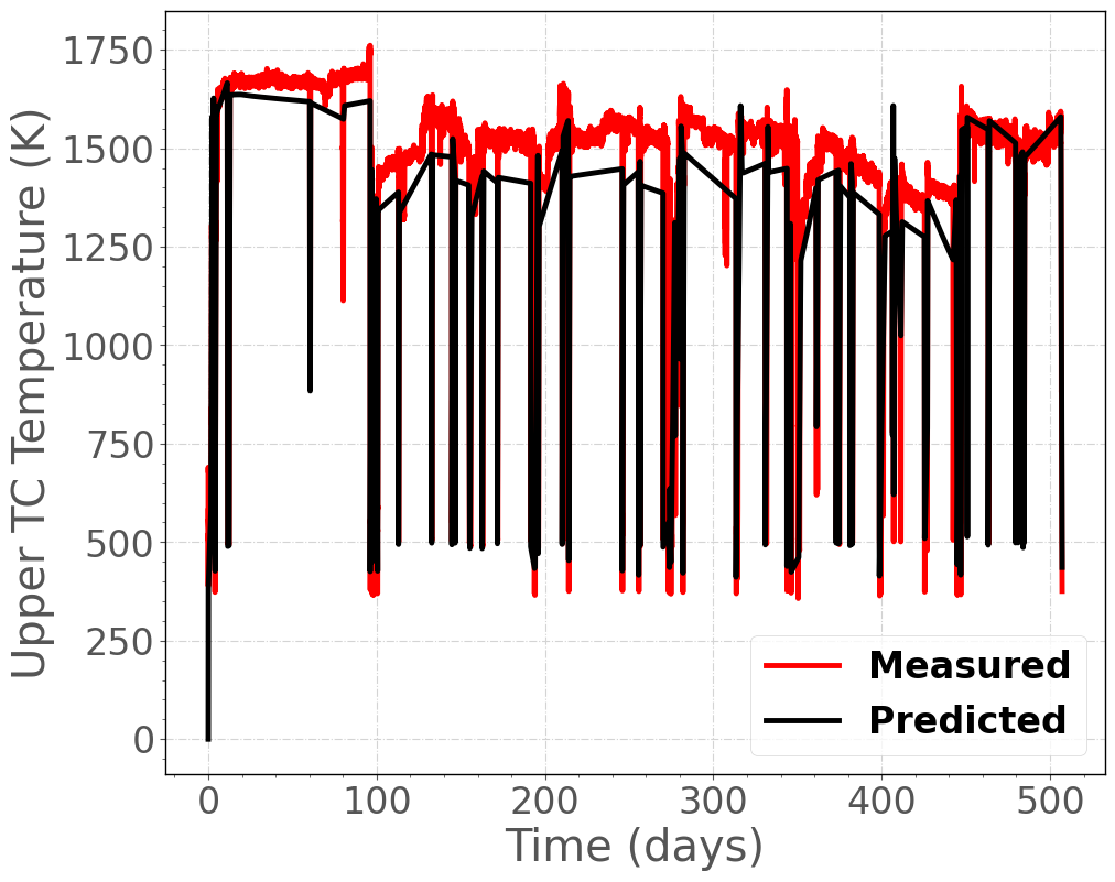
Figure 5: Comparison of predicted and measured fuel centerline temperature histories at the upper thermocouple location for IFA-677.1 Rod 5.
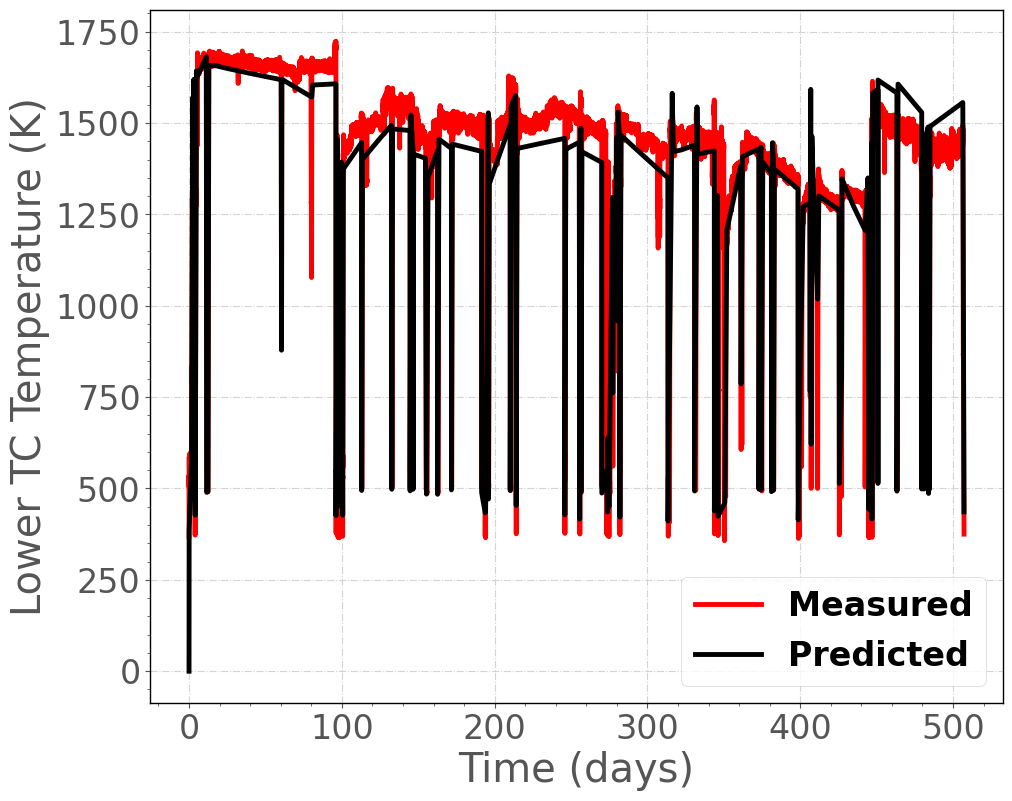
Figure 6: Comparison of predicted and measured fuel centerline temperature histories at the lower thermocouple location for IFA-677.1 Rod 5.
Fission Gas Release
The calculated fission gas release as a function of rod average burnup is shown in Figure 7 along with the measured data (which are inferred from the inner rod pressure on-line measurement (Jos̆ek, 2008)). FGR is predicted accurately during the first 17 MWd/KgU. After that, FGR is underpredicted, with the calculated value at the end of life being 8% and the experimental value being 22%. The underprediction is consistent with the tendency to underpredict the fuel temperature, as FGR is mainly temperature driven. However, a discrepancy of up to a factor of 3 can be considered acceptable, in view of the inherent modeling uncertainties for FGR (Pastore et al., 2015). Similar results are observed for Rod 5 as shown in Figure 8.
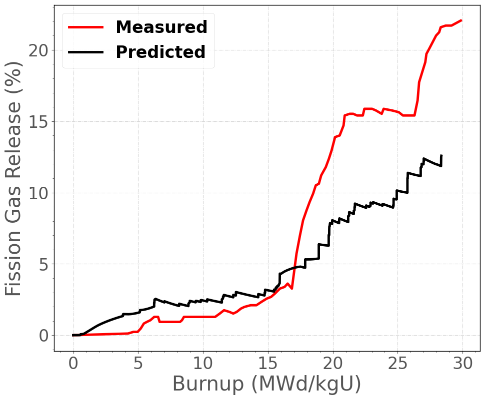
Figure 7: Comparison of predicted and measured fission gas release as a function of rod average burnup for IFA-677.1 Rod 1.
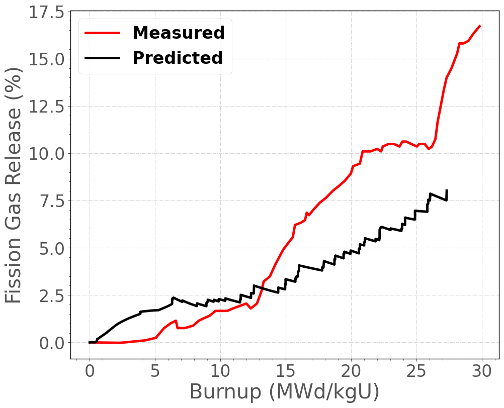
Figure 8: Comparison of predicted and measured fission gas release as a function of rod average burnup for IFA-677.1 Rod 5.
Rod inner pressure
In Figure 9, the time evolution of rod inner pressure calculated by BISON is compared to the experimental data from the pressure transducer in IFA-677.1 Rod 1. Prediction is accurate for the first three cycles of irradiation, although a moderate overprediction of the measured rod inner pressure is observed. Starting from the fourth cycle, BISON overpredicts the measured data. Discrepancies may be partly due to inaccuracies in the calculation of the plenum temperature. Similar results are observed for Rod 5 as shown in Figure 10.
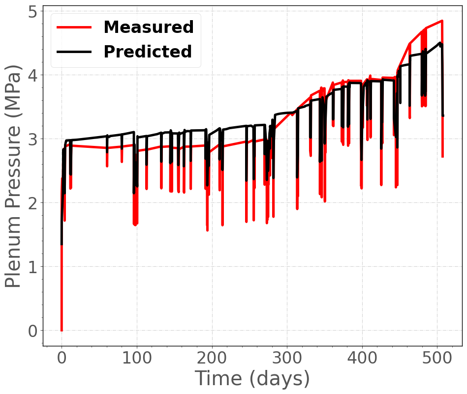
Figure 9: Comparison of predicted and measured inner rod pressure histories for IFA-677.1 Rod 1.
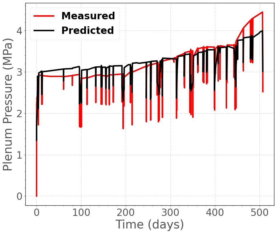
Figure 10: Comparison of predicted and measured inner rod pressure histories for IFA-677.1 Rod 5.
Fuel stack elongation
In Figure 11, the time evolution of fuel stack alongation calculated by BISON is compared to the experimental data in IFA-677.1 Rod 1. Similar results are observed for Rod 5 as shown in Figure 12.
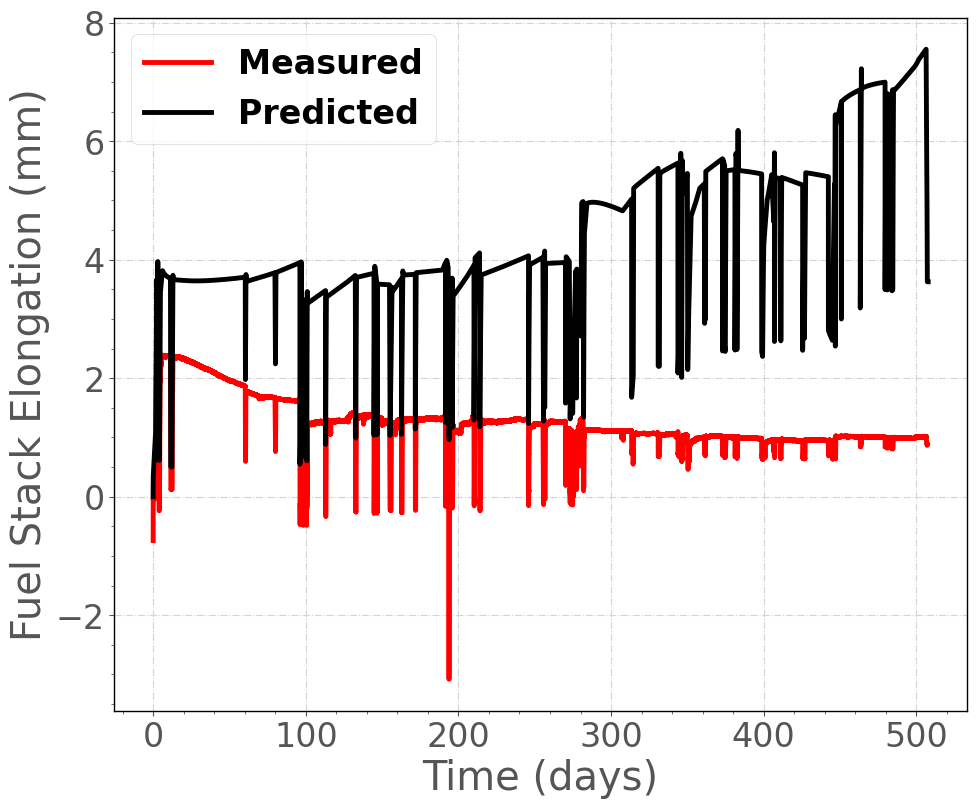
Figure 11: Comparison of predicted and measured fuel stack elongation histories for IFA-677.1 Rod 1.
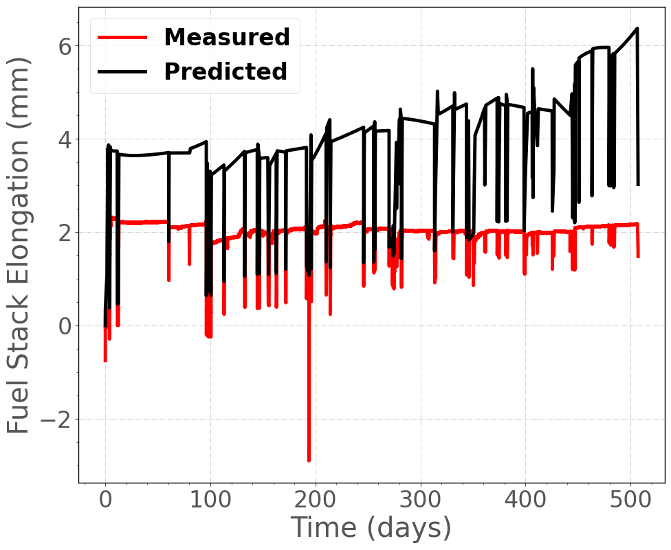
Figure 12: Comparison of predicted and measured fuel stack elongation histories for IFA-677.1 Rod 5.
References
- M. W. D. Cooper, C. R. Stanek, and D. A. Andersson.
The role of dopant charge state on defect chemistry and grain growth of doped UO$_2$.
Acta Materialia, 150:403–413, 2018.[BibTeX]
- H. K. Jenssen.
PIE Report on Six UO$_2$ Fuel Rods Irradiated in IFA-677 High Initial Rating Test.
Technical Report HWR-968, OECD Halden Reactor Project, March 2010.[BibTeX]
- R. Jo\u sek.
The High Initial Rating Test IFA-677: Final Report on In-Pile Results.
Technical Report HWR-872, OECD Halden Reactor Project, April 2008.[BibTeX]
- K. Lassmann, A. Schubert, J. van de Laar, and P. Van Uffelen.
The 'Fuel Rod Analysis ToolBox': a general program for preparing the input of a fuel rod performance code.
Annals of Nuclear Energy, 81:332–335, 2015.[BibTeX]
- OECDHRP.
Data Sheet / IFA-677.1.
Technical Report QA-F-702, OECD Halden Reactor Project, 2005.[BibTeX]
- G. Pastore, L.P. Swiler, J.D. Hales, S.R. Novascone, D.M. Perez, B.W. Spencer, L. Luzzi, P. Van Uffelen, and R.L. Williamson.
Uncertainty and sensitivity analysis of fission gas behavior in engineering-scale fuel modeling.
Journal of Nuclear Materials, 465:398–408, 2015.[BibTeX]
- W. Weisenak.
Modifications to ifa-677 data conversion.
Technical Report HWR-1263, Halden, 2019.[BibTeX]