- fragmentation_modelCOINDREAUThe model used to calculate the number of large fragments.
Default:COINDREAU
C++ Type:MooseEnum
Controllable:No
Description:The model used to calculate the number of large fragments.
- fuel_pin_geometryName of the UserObject that reads the pin geometry from the mesh.
C++ Type:UserObjectName
Controllable:No
Description:Name of the UserObject that reads the pin geometry from the mesh.
- layered_average_burnupName of the UserObject that contains the layered average burnup.
C++ Type:UserObjectName
Controllable:No
Description:Name of the UserObject that contains the layered average burnup.
- layered_clad_internal_volumeName of the UserObject that contains the layered internal volume.
C++ Type:UserObjectName
Controllable:No
Description:Name of the UserObject that contains the layered internal volume.
- layered_maximum_clad_radiusName of the UserObject that contains the layered maximum cladding inner radius.
C++ Type:UserObjectName
Controllable:No
Description:Name of the UserObject that contains the layered maximum cladding inner radius.
- layered_pulverized_fuel_volumeName of the UserObject that contains the layered average pulverized fuel volume.
C++ Type:UserObjectName
Controllable:No
Description:Name of the UserObject that contains the layered average pulverized fuel volume.
- max_linear_heat_generation_rateName of the Postprocessor that holds the max linear heat generation rate over time in W/m
C++ Type:PostprocessorName
Unit:(no unit assumed)
Controllable:No
Description:Name of the Postprocessor that holds the max linear heat generation rate over time in W/m
AxialRelocationUserObject
Tracks mass movement due to axial relocation of fuel during a Loss of Coolant Accident.
Description
AxialRelocationUserObject calculates movement of mass throughout a fuel rod during Loss of Coolant Accident (LOCA) conditions. First, the effective packing fraction of a crumbled mixture of two sizes of particles (larger fragments and smaller pulvers) is calculated, which determines how effective the packing of the crumbled fuel is in the distended regions of the cladding. Once the effective packing fraction is determined, the movement of the mass throughout the axial layers is computed. The model was original developed by Jernkvist and Massih (2015) for coupling to FRAPTRAN-1.5. FRAPTRAN-1.5 simulates fuel rods as numerous 1D radial slices with generalized plain strain characteristics in the axial direction. The implementation of the axial relocation model in BISON can make use of either the Layered1D Layered1DAction or Layered2D Layered2DAction capabilities.
Fuel Fragmentation and Packing Fraction
Prior to axially relocating fuel fragments, the amount and size of such fragments need to be quantified. In the model two fuel particle sizes are assumed and defined as fragments and pulvers. Fragments are larger fuel particles that exist throughout the irradiation history of the rod and begin forming due to fracture during the first rise to power. Pulvers are the smaller fuel particles that only form at high local burnups due to the disintegration of the high burnup fuel structure at the pellet periphery. For extremely high burnup rods there is the potential for the entire pellet to pulverize. The number of radial fragments can be computed by one of three fragmentation models: COINDREAU, WALTON, and BARANI. In the COINDREAU model (Coindreau et al., 2013), which is the default, the number of radial fragments formed in fresh fuel is obtained by: where is the number of radial fragments formed in fresh fuel subjected to a power at beginning of life, is the maximum linear heat generation rate experienced by the fuel in kW/m. Using the initial number of radial fragments calculated above, the number of radial fragments in irradiated fuel is determined by: where is the fuel pellet average burnup in MWd/kgHM. Notice that the above equations limit the maximum number of radial fragments to 16. In the WALTON model (Walton and Matheson, 1984), the number of radial fragments formed is computed by: (1) where is in the same units at the COINDREAU model. The term in equation~\ref{eq:walton_matheson} is known as the Macaulay brackets defined by: (2) where the units for are the same as the COINDREAU model. In the BARANI model (Barani et al., 2019), the number of radial fragments formed is given by: (3) where the units for is the same as the other models.
Once the number of radial fragments in irradiated fuel is known, the characteristic side length of the fragments is calculated by: where is the characteristic side length of the fragments and is the as-fabricated diameter of the fuel pellet. Before the packing fraction can be calculated the amount of pulverized fuel needs to be determined. This can be calculated by UO2Pulverization or UO2PulverizationMesoscale. Since the characteristics of pulverized fuel are not well known, Jernkvist and Massih (2015) argue that the characteristic side length of the pulvers () can be treated as a model parameter having a default value of 100 m. The mass fraction of pulvers () can be determined from the calculated volume of pulverized fuel to the known total volume of fuel. The mass fraction of fragments is then simply given by .
Once the mass fractions of both fragments and pulvers are known, an effective packing fraction can be determined using the methodology proposed by Westman (2015). The effective packing fraction () is determined by using an internal Newton iteration loop to solve the following: where
and is a parameter that depends upon the difference in shape between the fragments and pulvers. In the preceding equations and represent the packing fraction if the crumbled bed of fuel particles was entirely made up of fragments or pulvers respectively. Jernkvist and Massih suggest values of and . The parameter is calculated by: where and are the equivalent packing diameters of the pulvers and fragments. The equivalent packing diameter is determined via: where is the sphericity of the particle and is the volume of the particle. Jernkvist and Massih (2015) provides a table of possible shapes with their respective volumes and sphericities:
| Shape and dimension | ||
|---|---|---|
| Sphere with diameter s | 1.000 | |
| Cube with side s | 0.806 | |
| Octahedron with side s | 0.846 | |
| Ideal cylinder, h = s | 0.874 | |
| Triangular prism, h = s | 0.716 |
The default shape settings are proposed by Jernkvist and Massih (2015) with fragments represented as triangular prisms and pulvers as octahedrons. All table options are avaiable for both fragment and pulver shapes which will override the default sphericity values and volume calculations.
Axial Relocation Algorithm
Since this axial relocation model was originally developed to be coupled to FRAPTRAN-1.5 a layered approach was taken. Assuming the layers are indexed by and there are layers the condition on collapse of the fuel in a given layer is: where is the initial as-fabricated fuel mass in the layer and represents the mass in the layer if it is completely filled with crumbled fuel: where is the equivalent packing fraction in the layer, is the density of the fuel, is the height of the layer, and is the cladding inner radius for the layer. Two constraints are applied to prevent unrealistic phenomena from occurring. First, relocation can only occur in the downward direction, and second, the amount of fuel that can relocate into a layer is limited by the available mass of fuel existing in all layers above it. These lower () and upper () constraints can be cast into the following equations:
where the superscript represents the mass in the j:th layer at the beginning of the timestep () and represents the available mass to be relocated into the k:th layer. Two additional constraints are placed on the movement of mass in Jernkvist and Massih's model: (1) a residual amount of the initial fuel mass will remain in the layer throughout the simulation (denoted by ) and (2) the fuel-to-cladding gap must be large enough to accommodate fuel movement (denoted by ). The algorithm is divided into two loops, Figure 1, with the first beginning at the top layer and moving downwards to determine the amount of available mass to be relocated in each layer followed by a loop from the bottom layer to the top that enforces the upper and lower constraints while relocating the mass to the appropriate layers. In the second loop the and terms represent a nested conditional statement in the code.
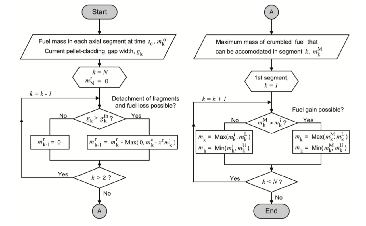
Figure 1: The two loops representing the axial relocation algorithm.
The algorithm for the two branches of the code is shown in Figure 1 for clarity. The left loop is executed first which determines the amount of relocatable mass that can accommodated in each layer. The right loop enforces the constraints and moves the mass to the appropriate layers. Reproduced from Jernkvist and Massih (2015).
Example Input Syntax
[UserObjects<<<{"href": "../../syntax/UserObjects/index.html"}>>>]
  [axial_relocation]
    type = AxialRelocationUserObject<<<{"description": "Tracks mass movement due to axial relocation of fuel during a Loss of Coolant Accident.", "href": "AxialRelocationUserObject.html"}>>>
    block<<<{"description": "The list of block ids (SubdomainID) that this object will be applied"}>>> = fuel
    direction<<<{"description": "The direction of the layers."}>>> = y
    num_layers<<<{"description": "The number of layers."}>>> = 5
    layered_average_burnup<<<{"description": "Name of the UserObject that contains the layered average burnup."}>>> = layered_average_burnup
    layered_pulverized_fuel_volume<<<{"description": "Name of the UserObject that contains the layered average pulverized fuel volume."}>>> = layered_pulverized_fuel_volume
    layered_maximum_clad_radius<<<{"description": "Name of the UserObject that contains the layered maximum cladding inner radius."}>>> = layered_maximum_clad_radius
    layered_clad_internal_volume<<<{"description": "Name of the UserObject that contains the layered internal volume."}>>> = layered_clad_internal_volume
    max_linear_heat_generation_rate<<<{"description": "Name of the Postprocessor that holds the max linear heat generation rate over time in W/m"}>>> = maximum_power
    fuel_pin_geometry<<<{"description": "Name of the UserObject that reads the pin geometry from the mesh."}>>> = fuel_pin_geometry
    execute_on<<<{"description": "The list of flag(s) indicating when this object should be executed. For a description of each flag, see https://mooseframework.inl.gov/source/interfaces/SetupInterface.html."}>>> = 'initial timestep_end'
  []
[]Input Parameters
- blockThe list of block ids (SubdomainID) that this object will be applied
C++ Type:std::vector<SubdomainName>
Controllable:No
Description:The list of block ids (SubdomainID) that this object will be applied
- density10431As-fabricated fuel pellet density
Default:10431
C++ Type:double
Unit:(no unit assumed)
Controllable:No
Description:As-fabricated fuel pellet density
- fragment_packing_fraction0.69The packing fraction of large fragments of fuel.
Default:0.69
C++ Type:double
Unit:(no unit assumed)
Controllable:No
Description:The packing fraction of large fragments of fuel.
- fragment_particle_shapeTriangular_PrismThe larger particle shape used to calculate the pulverized binary packing fraction: Sphere Cube Octahedron Ideal_Cylinder Triangular_Prism
Default:Triangular_Prism
C++ Type:MooseEnum
Controllable:No
Description:The larger particle shape used to calculate the pulverized binary packing fraction: Sphere Cube Octahedron Ideal_Cylinder Triangular_Prism
- gap_thickness_threshold0.0002The threshold gap thickness required for axial relocation.
Default:0.0002
C++ Type:double
Unit:(no unit assumed)
Controllable:No
Description:The threshold gap thickness required for axial relocation.
- layer_bounding_blockList of block ids (SubdomainID) that are used to determine the upper and lower geometric bounds for all layers. If this is not specified, the ids specified in 'block' are used for this purpose.
C++ Type:std::vector<SubdomainName>
Controllable:No
Description:List of block ids (SubdomainID) that are used to determine the upper and lower geometric bounds for all layers. If this is not specified, the ids specified in 'block' are used for this purpose.
- maximum_iterations10Maximum number of sub-newton iterations allowed when calculating the packing fraction
Default:10
C++ Type:unsigned int
Controllable:No
Description:Maximum number of sub-newton iterations allowed when calculating the packing fraction
- nonrelocatable_fuel_fraction0.01The fraction of the initial fuel in a layer that cannot relocate.
Default:0.01
C++ Type:double
Unit:(no unit assumed)
Controllable:No
Description:The fraction of the initial fuel in a layer that cannot relocate.
- output_iteration_infoFalseSet true to output sub-newton iteration information when calculating the packing fraction
Default:False
C++ Type:bool
Controllable:No
Description:Set true to output sub-newton iteration information when calculating the packing fraction
- pulver_characteristic_length0.0001The characteristic length of the pulvers.
Default:0.0001
C++ Type:double
Unit:(no unit assumed)
Controllable:No
Description:The characteristic length of the pulvers.
- pulver_packing_fraction0.72The packing fraction of the smaller pulvers of fuel.
Default:0.72
C++ Type:double
Unit:(no unit assumed)
Controllable:No
Description:The packing fraction of the smaller pulvers of fuel.
- pulver_particle_shapeOctahedronThe smaller particle shape used to calculate the pulverized binary packing fraction: Sphere Cube Octahedron Ideal_Cylinder Triangular_Prism
Default:Octahedron
C++ Type:MooseEnum
Controllable:No
Description:The smaller particle shape used to calculate the pulverized binary packing fraction: Sphere Cube Octahedron Ideal_Cylinder Triangular_Prism
- tolerance1e-10Absolute convergence tolerance for the sub-newton iteration used to calculate the packing fraction
Default:1e-10
C++ Type:double
Unit:(no unit assumed)
Controllable:No
Description:Absolute convergence tolerance for the sub-newton iteration used to calculate the packing fraction
Optional Parameters
- allow_duplicate_execution_on_initialFalseIn the case where this UserObject is depended upon by an initial condition, allow it to be executed twice during the initial setup (once before the IC and again after mesh adaptivity (if applicable).
Default:False
C++ Type:bool
Controllable:No
Description:In the case where this UserObject is depended upon by an initial condition, allow it to be executed twice during the initial setup (once before the IC and again after mesh adaptivity (if applicable).
- execute_onTIMESTEP_ENDThe list of flag(s) indicating when this object should be executed. For a description of each flag, see https://mooseframework.inl.gov/source/interfaces/SetupInterface.html.
Default:TIMESTEP_END
C++ Type:ExecFlagEnum
Controllable:No
Description:The list of flag(s) indicating when this object should be executed. For a description of each flag, see https://mooseframework.inl.gov/source/interfaces/SetupInterface.html.
- execution_order_group0Execution order groups are executed in increasing order (e.g., the lowest number is executed first). Note that negative group numbers may be used to execute groups before the default (0) group. Please refer to the user object documentation for ordering of user object execution within a group.
Default:0
C++ Type:int
Controllable:No
Description:Execution order groups are executed in increasing order (e.g., the lowest number is executed first). Note that negative group numbers may be used to execute groups before the default (0) group. Please refer to the user object documentation for ordering of user object execution within a group.
- force_postauxFalseForces the UserObject to be executed in POSTAUX
Default:False
C++ Type:bool
Controllable:No
Description:Forces the UserObject to be executed in POSTAUX
- force_preauxFalseForces the UserObject to be executed in PREAUX
Default:False
C++ Type:bool
Controllable:No
Description:Forces the UserObject to be executed in PREAUX
- force_preicFalseForces the UserObject to be executed in PREIC during initial setup
Default:False
C++ Type:bool
Controllable:No
Description:Forces the UserObject to be executed in PREIC during initial setup
Execution Scheduling Parameters
- average_radius1When using 'average' sampling this is how the number of values both above and below the layer that will be averaged.
Default:1
C++ Type:unsigned int
Controllable:No
Description:When using 'average' sampling this is how the number of values both above and below the layer that will be averaged.
- cumulativeFalseWhen true the value in each layer is the sum of the values up to and including that layer
Default:False
C++ Type:bool
Controllable:No
Description:When true the value in each layer is the sum of the values up to and including that layer
- positive_cumulative_directionTrueWhen 'cumulative' is true, whether the direction for summing the cumulative value is the positive direction or negative direction
Default:True
C++ Type:bool
Controllable:No
Description:When 'cumulative' is true, whether the direction for summing the cumulative value is the positive direction or negative direction
- sample_typedirectHow to sample the layers. 'direct' means get the value of the layer the point falls in directly (or average if that layer has no value). 'interpolate' does a linear interpolation between the two closest layers. 'average' averages the two closest layers.
Default:direct
C++ Type:MooseEnum
Controllable:No
Description:How to sample the layers. 'direct' means get the value of the layer the point falls in directly (or average if that layer has no value). 'interpolate' does a linear interpolation between the two closest layers. 'average' averages the two closest layers.
Value Sampling / Aggregating Parameters
- boundsThe 'bounding' positions of the layers i.e.: '0, 1.2, 3.7, 4.2' will mean 3 layers between those positions.
C++ Type:std::vector<double>
Unit:(no unit assumed)
Controllable:No
Description:The 'bounding' positions of the layers i.e.: '0, 1.2, 3.7, 4.2' will mean 3 layers between those positions.
- directionThe direction of the layers.
C++ Type:MooseEnum
Controllable:No
Description:The direction of the layers.
- direction_maxMaximum coordinate along 'direction' that bounds the layers
C++ Type:double
Unit:(no unit assumed)
Controllable:No
Description:Maximum coordinate along 'direction' that bounds the layers
- direction_minMinimum coordinate along 'direction' that bounds the layers
C++ Type:double
Unit:(no unit assumed)
Controllable:No
Description:Minimum coordinate along 'direction' that bounds the layers
- num_layersThe number of layers.
C++ Type:unsigned int
Controllable:No
Description:The number of layers.
Layers Extent And Definition Parameters
- control_tagsAdds user-defined labels for accessing object parameters via control logic.
C++ Type:std::vector<std::string>
Controllable:No
Description:Adds user-defined labels for accessing object parameters via control logic.
- enableTrueSet the enabled status of the MooseObject.
Default:True
C++ Type:bool
Controllable:Yes
Description:Set the enabled status of the MooseObject.
- use_displaced_meshFalseWhether or not this object should use the displaced mesh for computation. Note that in the case this is true but no displacements are provided in the Mesh block the undisplaced mesh will still be used.
Default:False
C++ Type:bool
Controllable:No
Description:Whether or not this object should use the displaced mesh for computation. Note that in the case this is true but no displacements are provided in the Mesh block the undisplaced mesh will still be used.
Advanced Parameters
- prop_getter_suffixAn optional suffix parameter that can be appended to any attempt to retrieve/get material properties. The suffix will be prepended with a '_' character.
C++ Type:MaterialPropertyName
Unit:(no unit assumed)
Controllable:No
Description:An optional suffix parameter that can be appended to any attempt to retrieve/get material properties. The suffix will be prepended with a '_' character.
- use_interpolated_stateFalseFor the old and older state use projected material properties interpolated at the quadrature points. To set up projection use the ProjectedStatefulMaterialStorageAction.
Default:False
C++ Type:bool
Controllable:No
Description:For the old and older state use projected material properties interpolated at the quadrature points. To set up projection use the ProjectedStatefulMaterialStorageAction.
Material Property Retrieval Parameters
Input Files
- (test/tests/axial_relocation/mass_relocation_translated.i)
- (test/tests/axial_relocation/crumbled_thermal_conductivity.i)
- (test/tests/axial_relocation/mass_relocation.i)
- (examples/axial_relocation/layered1D/single_balloon.i)
- (examples/axial_relocation/layered1D/twin_balloon.i)
- (test/tests/axial_relocation/axial_relocation_volume_correction.i)
- (test/tests/axial_relocation/packing_fraction.i)
- (test/tests/axial_relocation/axial_relocation_eigenstrain.i)
References
- T. Barani, D. Pizzocri, G. Pastore, L. Luzzi, and J.D. Hales.
Isotropic softening model for fuel cracking in BISON.
Nuclear Engineering and Design, 342:257–263, 2019.
doi:10.1016/j.nucengdes.2018.12.005.[BibTeX]
- O. Coindreau, F. Fichot, and J. Fleurot.
Nuclear fuel rod fragmentation under accidental conditions.
Nuclear Engineering and Design, 255:68–76, 2013.[BibTeX]
- L. O. Jernkvist and A. Massih.
Model for axial relocation of fragmented and pulverized fuel pellets in distending fuel rods and its effects on fuel rod heat load.
Technical Report SSM-2015:37, Strål säkerhets myndigheten, 2015.[BibTeX]
- L. O. Jernkvist and A. R. Massih.
Modeling axial relocation of fragmented fuel pellets inside ballooned cladding tubes and its effects on lwr fuel rod failure behavior during loca.
In Transactions of SMIRT-23. Manchester, UK, 2015.[BibTeX]
- L. A. Walton and J. E. Matheson.
FUMAC - a new model for light water reactor fuel relocation and pellet-cladding interaction.
Nuclear Technology, 64:127–138, 1984.[BibTeX]
- A. E. R. Westman.
The packing of particles: empirical equations for intermediate diameter ratios.
Journal of the American Ceramic Society, 76(11):127–129, 2015.[BibTeX]