Fuel Behavior Test Apparatus Experiments
The Fuel Behavior Test Apparatus (FBTA) assessment case simulates a series of out-of-pile transient experiments performed in the FBTA facility at Argonne's Alpha-Gamma Hot Cell Facility (AGHCF) (Tomchik, 2021).
Overview
The objective of the FBTA series experiments was to capture a liquid eutectic penetration of cladding under elevated temperature conditions typically found during a transient event. This assessment case is focused on the evaluation and assessment of the metallic fuel-cladding compatibility models in BISON, especially the liquid eutectic penetration model. The more comprehensive out-of-pile transient experiments that cover other complex fuel performance phenomena are the Whole Pin Furnace (WPF) experiments, which will be covered by a separate assessment case.
Test Description
The FBTA was an in-cell out-of-pile transient experiment apparatus that was developed during the IFR program. Since its establishment, a series of out-of-pile transient tests for in-pile-irradiated metallic fuel with cladding had been conducted in the FBTA facility (see Figure 1). Due to the limitation in sample dimension of the FBTA facility, only a segment of fuel slug with cladding sectioned from an in-pile-irradiated metallic fuel pin could be tested.
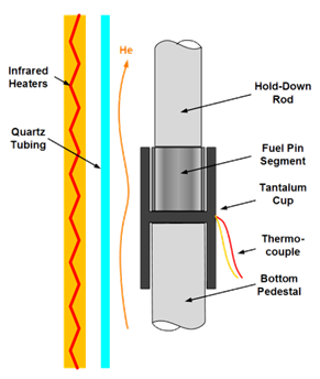
Figure 1: Experiment setup of the Fuel Behavior Test Apparatus (FBTA).
That is, a typical specimen tested in FBTA was an irradiated fuel-cladding couple without released fission gas measured. As a result, the FBTA setup was mainly used to investigate the compatibility between irradiated fuel and cladding at elevated temperatures during transient scenarios. To be specific, liquid phase has been found to form due to eutectic melting of U(Pu)-Fe in the presence of fission products and to penetrate cladding. The FBTA investigations were designed to obtain the reaction kinetics of this liquid phase penetration phenomenon.
During the IFR program, over 140 irradiated specimens were tested in the FBTA facility from 1988 to 1993. The specimens were mainly sectioned from EBR-II irradiated fuel pins, with some exceptions from FFTF irradiated fuel pins. The tested fuel slugs include both binary and ternary fuels with burnup ranging from 3 to 17 at.%, while the tested cladding covers all three main fast reactor cladding materials, HT9, D9, and 316SS. These tests were of the constant-temperature type; the temperature and duration of the tests typically ranged from 700 to 850 °C and 0.1 to 7.0 hours, respectively. The results of these tests form the foundation of the current knowledge on fuel-cladding compatibility under transient conditions.
The FBTA assessment has been enhanced to cover 124 FBTA tests, which account for almost all the tests with quality results. These tests utilized 23 metallic fuel pins irradiated in 7 subassemblies in EBR-II and 1 subassembly in FFTF. Therefore, the tested fuel specimens covered in this assessment case include all three common metallic fuel cladding materials (i.e., HT9, CWD9, and CW316SS) and three Pu content values (i.e., 0 wt.%, 19 wt.%, and 26 wt.%). A detailed list of the involved pins can be found in Table 1. After the FBTA tests, metallograph examinations were performed on the specimens to determine the extent of cladding penetration and fuel melting.
Table 1: Irradiated fuel pins used for FBTA test specimens preparation
| Index | Reactor | Subassembly ID | Pin ID | Fuel Type | Cladding Type | Covered FBTA Tests | Pin BU | Comments |
|---|---|---|---|---|---|---|---|---|
| 1 | EBR-II | X420 | T224 | U-26Pu-10Zr | CWD9 | 3 | 6 | |
| 2 | EBR-II | X421 | T248 | U-10Zr | CWD9 | 3 | 10 | |
| 3 | EBR-II | X421/A | T106 | U-19Pu-10Zr | CWD9 | 4 | 17 | |
| 4 | EBR-II | X421/A | T227 | U-10Zr | CWD9 | 6 | 17 | |
| 5 | EBR-II | X421A | T536 | U-10Zr | CWD9 | 3 | 9.3 | |
| 6 | EBR-II | X423/A/B/C | T323 | U-10Zr | CW316SS | 7 | 4.6 | |
| 7 | EBR-II | X423/A/B/C | T326 | U-26Pu-10Zr | CW316SS | 12 | 4.7 | |
| 8 | EBR-II | X425 | T437 | U-10Zr | HT9 | 4 | 3 | |
| 9 | EBR-II | X425 | T459 | U-19Pu-10Zr | HT9 | 7 | 3 | |
| 10 | EBR-II | X429 | T619 | U-10Zr | HT9 | 5 | 8 | Settled sodium |
| 11 | EBR-II | X429/A/B | T581 | U-19Pu-10Zr | CW316SS | 3 | 13.5 | sheared cladding |
| 12 | EBR-II | X429/A/B | T608 | U-19Pu-10Zr | HT9 | 4 | 13.5 | sheared cladding |
| 13 | EBR-II | X430/A | T678 | U-26Pu-10Zr | HT9 | 4 | 2.3 | |
| 14 | EBR-II | X441 | DP17 | U-19Pu-10Zr | HT9 | 9 | 5.6 | |
| 15 | EBR-II | X441 | DP32 | U-19Pu-14Zr | HT9 | 1 | 6.2 | High Zr |
| 16 | EBR-II | X441 | DP27 | U-19Pu-6Zr | HT9 | 1 | 4.9 | Low Zr |
| 17 | EBR-II | X441/A | DP21 | U-19Pu-10Zr | HT9 | 10 | 11.1 | |
| 18 | EBR-II | X441/A | DP24 | U-19Pu-6Zr | HT9 | 6 | 10 | Low Zr |
| 19 | EBR-II | X441/A | DP45 | U-19Pu-10Zr | HT9 | 4 | 9.8 | 85% Smeared Density |
| 20 | EBR-II | X441/A | DP16 | U-19Pu-10Zr | HT9 | 9 | 11.3 | |
| 21 | EBR-II | X441/A | DP29 | U-19Pu-14Zr | HT9 | 2 | 12.3 | High Zr |
| 22 | EBR-II | X441/A | A850 | U-19Pu-10Zr | CWD9 | 5 | 11.2 | |
| 23 | FFTF | AK181 (IFR1) | 193 | U-19Pu-10Zr | CWD9 | 12 | 9.4 | Full Size Pin |
As summarized in Table 1, 22 pins irradiated in 7 subassemblies in EBR-II were involved in the 112 FBTA tests. The majority of these pins were typical EBR-II irradiated pins with three main cladding materials, U-xPu-10Zr fuel, and standard 75% smeared density. Four pins were ternary metallic fuel pins with higher (14Zr) and lower (6Zr) than usual Zr content, whereas one pin had 85% smeared density. These outlier pins contributed to only 14 out of 112 FBTA tests.
Additionally, three pins were irradiated in either subassembly X423 or subassembly X430, which have bigger fuel and cladding diameters than typical EBR-II pins. Another three pins were irradiated in subassembly X429, which was the IFR experiment that was designed to test pre-defected pins. Among these three pins, one pin was filled with half of the standard amount of sodium that was horizontally settled, while the cladding of the other two pins were sheared before irradiation.
BISON-FIPD and BISON-OPTD Integration
To simulate a FBTA test, two BISON simulations are needed. The first one is a steady state irradiation simulation to obtain the initial fuel and cladding conditions prior to the transient test. The second one is a transient simulation to simulate the out-of-pile heating stage of the FBTA test.
For the first stage, the BISON-FIPD integration powered simulation approach, as used in the X447 Assessment Case, is adopted for the aforementioned 23 irradiated pins. For the second stage, as the out-of-pile transient experiment data are maintained in the Out-of-Pile Transient Database (OPTD) database (Tomchik and Oaks, 2020), the simulation is enabled by the BISON-OPTD integration. Both test condition parameters and posttest measurement data from OPTD are used to help establish the simulation model and to evaluate the simulation results.
Model Description
The first stage (i.e., steady state irradiation in EBR-II/FFTF subassemblies) simulation is similar to the setup in the X447 Assessment Case. So the model description here is focused on the second stage (i.e., out-of-pile heating in FBTA facility) simulation, including how the data generated at the first stage simulation are used as the initial conditions.
The FBTA assessment case is focused on the liquid eutectic penetration of the cladding during out-of-pile transients and corresponding fuel melting. As a 2D-RZ axisymmetric model is used for the steady-state whole pin irradiation simulation, and the FBTA test specimen is an approximately 0.3 inch long section, a 1D-R model is sufficient for the out-of-pile transient simulation. The adoption of a 1D-R model also helps to reduce the computational cost and enable potential future implementation of all the FBTA tests in this assessment case to provide statistical results.
In addition, as mentioned above, artificial defects were applied to the three X429 pins before irradiation. The current BISON-FIPD integration-powered fuel pin model has several limitations in simulating these special pins. For instance, accurately simulating the fuel pin with settled sodium requires a 3D model instead of the current 2D-RZ model. Additionally, the reduced amount of fill sodium should be considered in the related models. Despite these limitations, the key parameters needed for the adopted fuel-cladding eutectic melting model, including local burnup, are minimally affected. Therefore, the current steady-state fuel performance simulations for these pins remain useful for the follow-up furnace stage simulations. In the future, if the mechanistic model requires additional parameters from steady-state simulations that are impacted by these limitations, the steady-state model will need to be improved.
Geometry and Mesh
The transient stage of the FBTA assessment case uses a 1D-R mesh consisting of both cladding and fuel. Like the 2D-RZ mesh used for the steady state simulation, the fuel and cladding blocks are not bonded but are connected by a contact model. Due to the simplicity of the FBTA test, mechanical contact is neglected so that only a thermal contact model is used to thermally connect the fuel and cladding blocks.
The mesh is generated using a series of MOOSE intrinsic mesh generators.
Material and Behavioral Models
Based on the focus of the FBTA assessment case, only the thermophysical models and the liquid penetration models are used in this assessment case:
ADUPuZrThermal: Calculates the thermal conductivity and specific heat for UPuZr fuel
ADHT9Thermal/ADD9Thermal/ADSS316Thermal: Calculates the thermal conductivity and specific heat for HT9/CWD9/CW316SS cladding
ADMetallicFuelLiquidCladdingPenetration: Calculates the liquid penetration rate of UPuZr fuel into HT9/CWD9/CW316SS cladding and the corresponding fuel melting
For the liquid penetration modeling, three different model options available in ADMetallicFuelLiquidCladdingPenetration, Tsai's legacy correlation, the ANL conservative correlation, and the ANL best estimate (least squares) correlation, are used to evaluate the simulation results. A set of empirical fuel melting correlations, which were recently developed based on FBTA results and have been implemented into ADMetallicFuelLiquidCladdingPenetration is used to calculate the fuel melting region size.
Loading of the Steady State Simulation Results
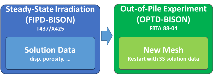
Figure 2: Schematic drawing of the restarting approach to initiate a FBTA simulation based on a whole pin steady state simulation result.
A comprehensive set of fuel performance related data are calculated during the steady state simulation for the whole fuel pin. As only a small section of the fuel pin is used in the FBTA test, only a subset of the data is needed for the transient simulation. Meanwhile, only the physical quantities that are related to liquid penetration need to be loaded for the transient simulation. Thus, in this assessment case, for the transient stage, a 1D-R new mesh is generated and the steady state output exodus file is loaded in a sub-application to extract the needed data, and only the needed data are transferred from the sub-application and loaded to the new mesh. The procedure is illustrated in Figure 2.
The loaded data are summarized in Table 2.
Table 2: List of steady state calculated data loaded for transient simulation.
| Data Name | Description |
|---|---|
temperature | Fuel and cladding temperature |
porosity | Fuel porosity used to correct thermal conductivity |
burnup | Fuel burnup needed by the liquid penetration model |
disp_x | Radial displacement |
id_wastage | Steady state FCCI wastage |
od_wastage | Steady state CCCI wastage |
Input files
The parametrized input files for the steady state stage 2D-RZ whole fuel pin models are located at bison/assessment/metallic_fuel/FBTA/analysis/steady_state. The corresponding FIPD-based data files for all the 23 irradiated pins are located in the bison/fipd-bison-integration-data/ submodule folder. FIPD users may manually download needed data files and modify assessment inputs to use these downloaded files if they do not have the fipd-bison-integration-data submodule setup.
The input files used to extract key information from the steady-state irradiation stage simulation and to create initial conditions for the furnace stage tests are located at bison/assessment/metallic_fuel/FBTA/analysis/fbta_initialization folder.
The input files for the furnace transient stage 1D-R FBTA models are generated automatically using a python script bison/assessment/metallic_fuel/FBTA/analysis/fbta_run/fbta_input_file_batch_gen.py, as the main body of the input files are the same for all the 124 tests, while the specific parameters are generated based on a FBTA data summary file fbta_batch_run.csv stored in the fipd-bison-integration-data submodule. The CSV file is a summary of the FBTA data available in the report (Tomchik, 2021) and related FIPD data.
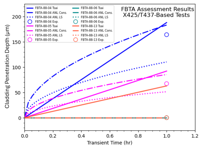
Figure 3: Comparison of the four FBTA tests in this assessment case (cladding penetration).
Results Comparison
Cladding Penetration
As an example for specific cases, the kinetics of the cladding penetration of the four representative FBTA tests (based on pin T437 of subassembly X425) in this assessment case are shown in Figure 3. The results from three different liquid penetration models are compared. Also plotted in Figure 3 is the experimentally measured penetration depth. It is clear that both the Tsai's legacy correlation and the improved ANL conservative correlation slightly over-estimate penetration depth in comparison to the measured value, providing conservative predictions as they are meant to do. On the other hand, the improved ANL best estimate correlation provides slightly under-estimated penetration depth.
For FBTA-88-13 test, which was conducted at 725 °C, experimentally no penetration was observed. The legacy Tsai's correlation predicts some penetration, while the improved ANL conservative correlation predicts no penetration, showing an improvement of the ANL conservative correlation.
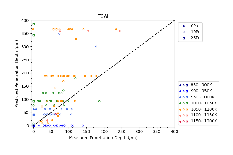
Figure 4: Summary of the performance of the TSAI correlation in predicting cladding penetration.
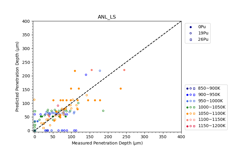
Figure 5: Summary of the performance of the ANL_LS correlation in predicting cladding penetration.
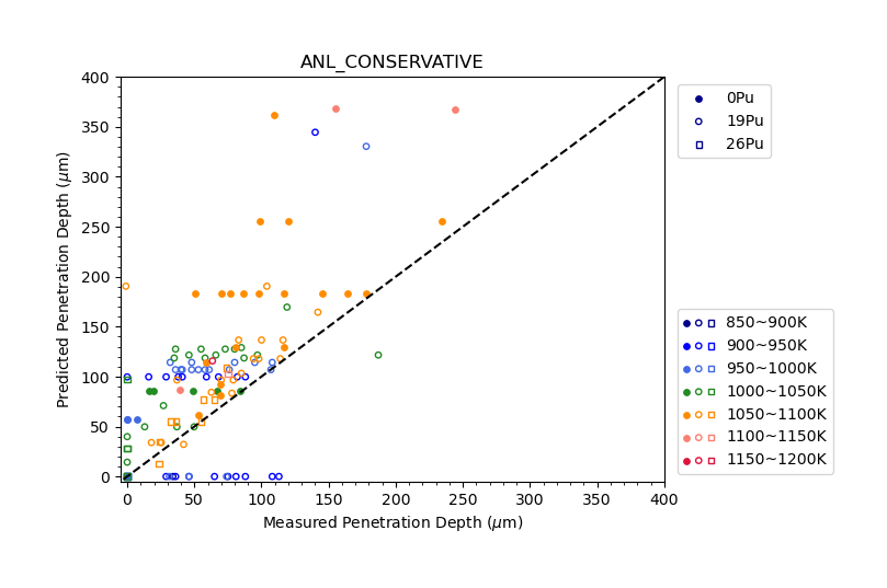
Figure 6: Summary of the performance of the ANL_CONSERVATIVE correlation in predicting cladding penetration.
The statistical comparisons based on all the 124 FBTA tests covered by this assessment case are illustrated in Figure 4, Figure 5, and Figure 6, respectively. These statistical figures show a clear trend that the ANL best estimate correlation and the ANL conservative correlations provide overall improved predictions on liquid cladding penetration depth for various fuel types and testing conditions.
Fuel Melting
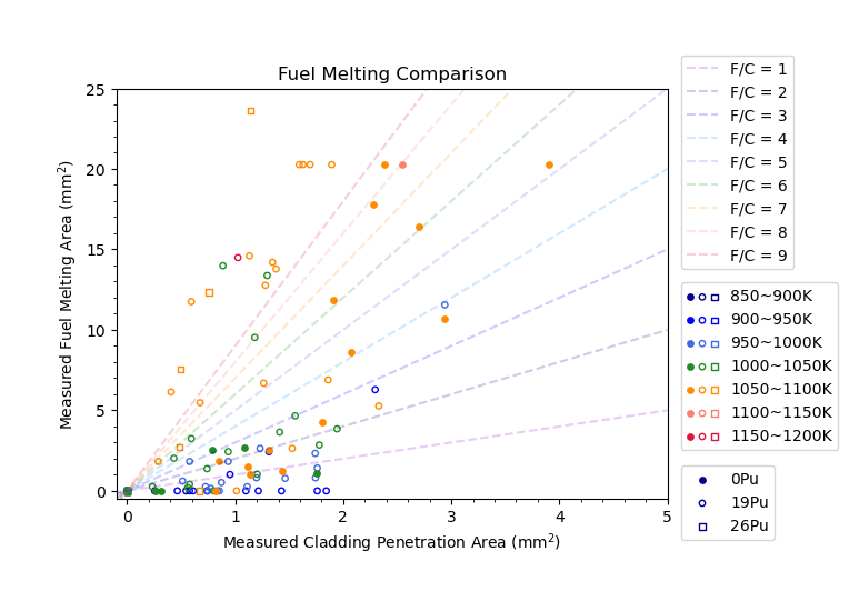
Figure 7: Fuel melting to cladding penetration area ratio as observed in FBTA tests.
The current ADMetallicFuelLiquidCladdingPenetration also contains the optional functionality to calculate the thickness of a fuel melting zone based on the predicted cladding penetration depth, assuming the fuel melting occurs symmetrically. The correlation basically assumes a volume ratio between molten fuel and penetrated cladding. The experimentally observed volume ratios are summarized in Figure 7 and show a strong dependence on furnace testing temperature and fuel composition.
Such a volume ratio can be provided by users based on their knowledge about the specific simulated cases. Alternatively, users can adopt a set of intrinsic empirical correlations in ADMetallicFuelLiquidCladdingPenetration. These temperature, burnup, and fuel composition dependent correlations were deduced using the Fe-U-Pu ternary phase diagram with correction factors fitted to the FBTA tests observation (as in Figure 7). In this assessment case, the empirical correlations option is employed. The predicted fuel melting zone areas of all the covered FBTA tests are compared with the measured values based on actual posttest metallography, as shown in Figure 8, Figure 9, and Figure 10. Again, the ANL best estimate correlation and the ANL conservative correlation provide overall improved predictions on fuel melting, whereas advanced mechanistic models being developed are expected to further improve model agreement with the experiment data.
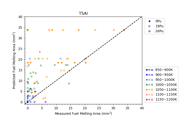
Figure 8: Summary of the performance of the TSAI correlation in predicting fuel melting.
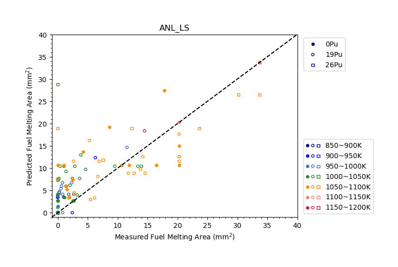
Figure 9: Summary of the performance of the ANL_LS correlation in predicting fuel melting.
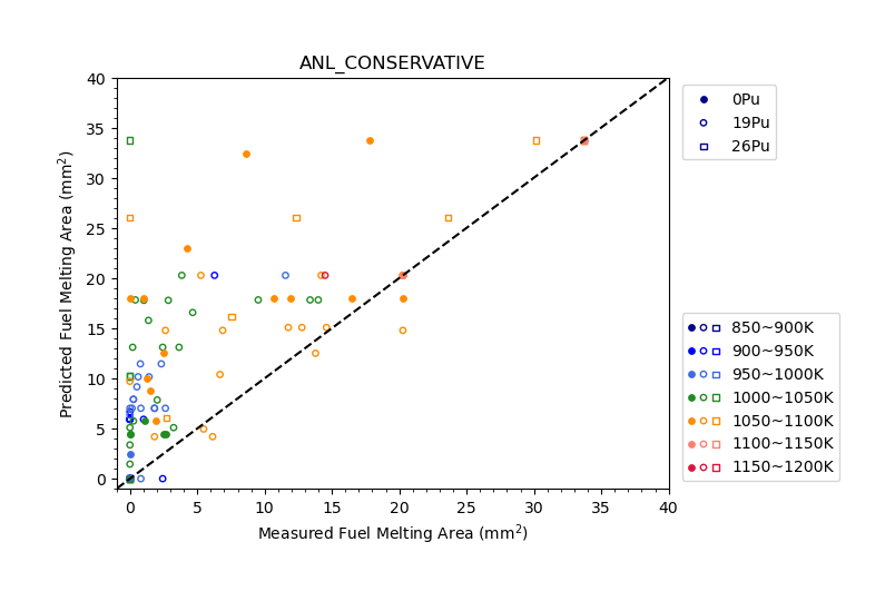
Figure 10: Summary of the performance of the ANL_CONSERVATIVE correlation in predicting fuel melting.
Discussion
The FBTA assessment case provides a platform to assess the performance of liquid cladding penetration model as well as the corresponding fuel melting model in BISON. Although the current BISON models are empirical and relatively simple, the FBTA assessment case also has the potential to be used as a calibration and evaluation tool for future mechanistic models informed by lower length scale simulations.
References
- Carolyn Tomchik.
Out-of-pile furnace tests on fast reactor metallic fuels conducted at the AGHCF.
Technical Report ANL-ART-217, Argonne National Laboratory, 3 2021.
doi:10.2172/1779724.[BibTeX]
- Carolyn Tomchik and Aaron Oaks.
Status and availability of OPTD, the out-of-pile transient database.
Technical Report ANL-ART-214, Argonne National Laboratory, 9 2020.
doi:10.2172/1690266.[BibTeX]