TRIBULATION BN1/3, BN1/4, and BN3/15
Overview
The objectives of the TRIBULATION (Tests Relative to High BUrnup Limitations Arising Normally in LWR's) International Programme were to 1) assess fuel rod behaviour at high burnup with an earlier transient and 2) to investigate the behaviour of different fuel rod designs and manufacturers when subjected to a steady state irradiation history to high burn-up. The program was organized jointly by BelgoNucleaire and the Nuclear Energy Centre at Mol (CEN/SCK) with the co-sponsorship of 14 participating organizations (Lippens and Boulanger, 1989). For the purpose of this fuel analysis problem, three out of the 19 fuel rods from the TRIBULATION Database (IFPETD, 2002) were evaluated with BISON. The three fuel rods were fabricated by BelgoNucleaire (BN) and are referred to as test rods BN1/3, BN1/4 and BN3/15 in this document. All three rods used standard Zircaloy-4 cladding and were discharged at rod average burnups of approximately 51.6, 51.2, and 51.1 MWd/kgU, respectively. Non-destructive post irradiation examination (PIE) was performed at various stages throughout testing of the BN rods for cladding creep down, cladding ovalization, rod growth and fuel column length changes. Destructive PIE was performed at the end-of-life for fission gas release and internal void volume. This experiment was chosen for analysis because of the availability of measured data for evaluation of several fuel rod performance characteristics including fission gas release, cladding creep down, fuel column length changes, rod growth and end-of-life internal free volume.
Test Description
Rod Design Specifications
An overview of the test matrix and cross reference identification data for BN1/3, BN1/4 and BN3/15 are shown below in Table 1 (IFPETD, 2002). The specific geometric input parameters for the test rods are summarized in Table 2. BN1/3 contained fuel pellets from two different batches with slightly different pellet mean densities. This simulation assumed the same pellet density of 10.408 g/cm for test BN1/3 because the two densities were close to each other. The fuel pellets for BN1/3 and BN1/4 have an initial enrichment of 8.25 while BN3/15 had an initial enrichment of 5.76%. The cladding material for all three rods was Zircaloy-4. The cladding was stress relieved at 460 C for 2.5 hours. BN1/3 and BN1/4 were pressurized with helium to 1.96 MPa (20 kg/cm) while BN3/15 was pressurized to 0.098 MPa (1 kg/cm).
Table 1: Overview of test matrix for test rods BN1/3, BN1/4 and BN3/15
| Matrix No. | Test No. | Rod No. | BR3 cycle Nos. | BR2 transient Power (kW/m) | BR3 cycle Nos. | History |
|---|---|---|---|---|---|---|
| 3 | BN1/3 | 3-47 | 4B | 34.7(for 540 sec) | 4C, 4D1 | NDT, T, NDT, |
| BR3(4C+4D), NDT, DT | ||||||
| 4 | BN1/4 | 3-342 | 4B | 4C, 4D1 | NDT, BR3(4C+4D), | |
| NDT, DT | ||||||
| 15 | BN3/15 | 1-610 | 4A, 4B | 4D2 | NDT, BR3(4D), | |
| NDT, DT |
NDT = non destructive tests
DT = destructive tests
T = transient irradiation in BR2
Table 2: BN1/3, BN1/4 and BN3/15 Rod Specifications.
| Fuel Rod | BN1X3 | BN1X4 | BN3X15 | Unit |
|---|---|---|---|---|
| Overall length | 1.1352 | 1.1360 | 1.1358 | m |
| Fuel stack height | 1.0019 | 0.9976 | 0.9956 | m |
| Upper plenum height | 88.3 | 93.4 | 95.2 | mm |
| Fill gas composition | He | He | He | |
| Fill gas pressure | 1.96133 | 1.96133 | 0.09807 | MPa |
| Fuel | BN1/3 | BN1/4 | BN3/15 | Unit |
| Material | UO | UO | UO | |
| Enrichment | 8.25 | 8.25 | 5.76 | |
| Pellet mean density | 10.408-10.340 | 10.355 | 10.435 | g/cm |
| Pellet mean density | 94.965-94.345 | 94.474 | 95.037 | |
| Outer diameter | 8.04 | 8.04 | 8.04 | mm |
| Nominal diametral gap | 200 | 200 | 200 | m |
| Average grain size | 11 | 11 | 10 | m |
| Cladding | BN1/3 | BN1/4 | BN3/15 | Unit |
| Material | Zr-4 | Zr-4 | Zr-4 | |
| Outer diameter | 9.50 +/- 0.04 | 9.50 +/- 0.04 | 9.50 +/- 0.04 | mm |
| Inner diameter | 8.24 +/- 0.04 | 8.24 +/- 0.04 | 8.24 +/- 0.04 | mm |
| Wall thickness | not <0.58 | not <0.58 | not <0.58 | mm |
Operating Conditions and Irradiation History
The irradiation of the BelgoNucleaire (BN) fuel rods chosen for the TRIBULATION programme was carried out in the BR2 and BR3 reactors of the Nuclear Energy Centre at Mol at Mol-Belgium (CEN/SCK). The base irradiation for BN1/3, BN1/4 and BN3/15 was performed in the BR3 reactor up to a specified preconditioning burnup between 20 and 40 GWd/tM peak pellet. Following the base irradiation, the rods were non-destructively examined. BN1/3 was transferred to the BR2 reactor for fast operational transient testing and then continued further irradiation in BR3. The fast operational transient for test BN1/3 consisted of a preconditioning period of at approximately 2 days 26600 W/m, followed by a rapid power increase to 35400 W/m at a ramp rate of approximately 1960 W/m/s. After a hold period of about 9 minutes, the power was then rapidly decreased to near the preconditioning level. Following the base irradiation and non-destructive exmaination, BN1/4 and BN3/15 were transferred back to the BR3 reactor for further irradiation.
The power mode selected for this simulation is PiecewiseConstant. The power histories for BN1/3, BN1/4, and BN3/15 are shown in Figure 1, Figure 2 and Figure 3, respectively. These three power histories assumed a 24 hour startup time that was broken into 24 timesteps of one hour increments. Because the axial power shapes and boundary conditions are modeled as PieceswiseBilinear, a ramp time of 360 seconds (0.1 hours) was assumed at each power step for the axial power shape and boundary condition input. The startup time of 24 hours and the ramp time of 360 seconds (0.1 hours) are based on ANATECH's experience with fuel rod modeling for steady state operation and the development of Falcon Verification and Validation cases. They are intended to minimize the introduction of computational artifacts from unrealistic power changes and ramp rates into the analyses. The axial power profile and cladding outer surface temperature profile as a function of time were calculated from the TRIBULATION data package (IFPETD, 2002). The initial fill-gas (Helium) pressure was 1.96 MPa for BN1/3 and BN1/4 and 0.098 MPa for BN3/15. The coolant system pressure was 13.729 MPa for the BR3 irradiation and 14.0 MPa for the BR2 irradiation. The fast neutron flux profile was scaled to a factor of 4.8e17. Operational input parameters are summarized in Table 3.
Table 3: Operational input parameters
| Base Irradiation | ||
|---|---|---|
| Coolant inlet temperature | K | 529.15 |
| Coolant pressure for BR3 Irradiation | MPa | 13.729 |
| Coolant pressure for BR2 Irradiation | MPa | 14.0 |
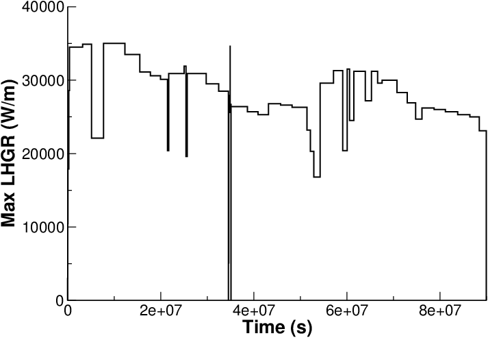
Figure 1: BN1/3 power history
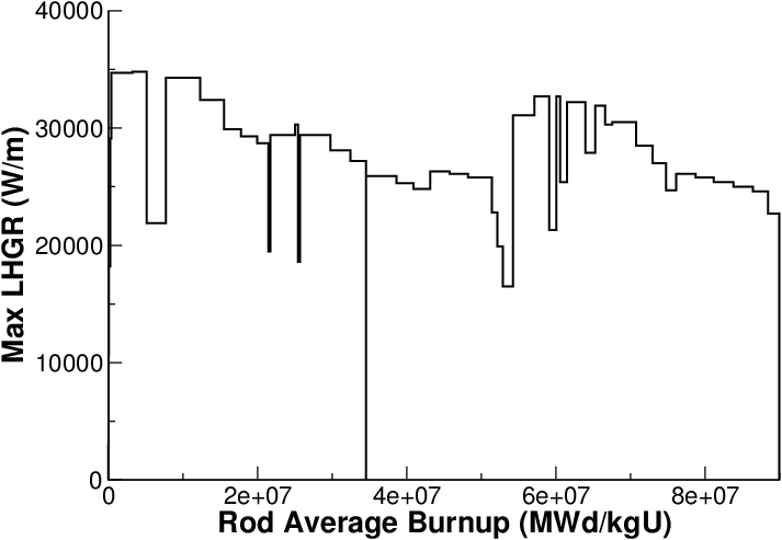
Figure 2: BN1/4 power history
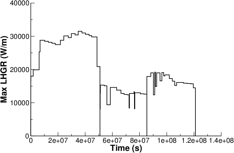
Figure 3: BN3/15 power history
Model Description
Geometry and Mesh
The rod specifications in Table 2 were used to define the geometry for these simulations. The BN1/3, BN1/4 and BN3/15 rods were modeled as a two-dimensional, axi-symmetric linear mesh with quadratic elements. The fuel mesh for all three rods consisted of 11 radial elements and the cladding mesh consisted of four radial elements to form a cladding thickness of 0.63 mm. In order to accurately model the fuel rod initial free volume, the overall fuel rod length and upper plenum height were adjusted during mesh generation to account for the volume of the plenum spring which is not explicitly modeled. The overall fuel rod lengths for BN1/3, BN1/4, and BN3/15 were reduced from 1135.2 mm, 1136.0 mm, and 1135.8 mm to 1081.01 mm, 1081.46 mm and 1081.34 mm, respectively. The plenum heights for BN1/3, BN1/4, and BN3/15 were reduced from 88.3 mm, 93.4 mm, and 95.2 mm to 67.5 mm, 71.3 mm, and 73.1 mm, respectively. The TRIBULATION BN1/3, BN1/4 and BN3/15 meshes are shown in Figure 4, Figure 5 and Figure 6 respectively.
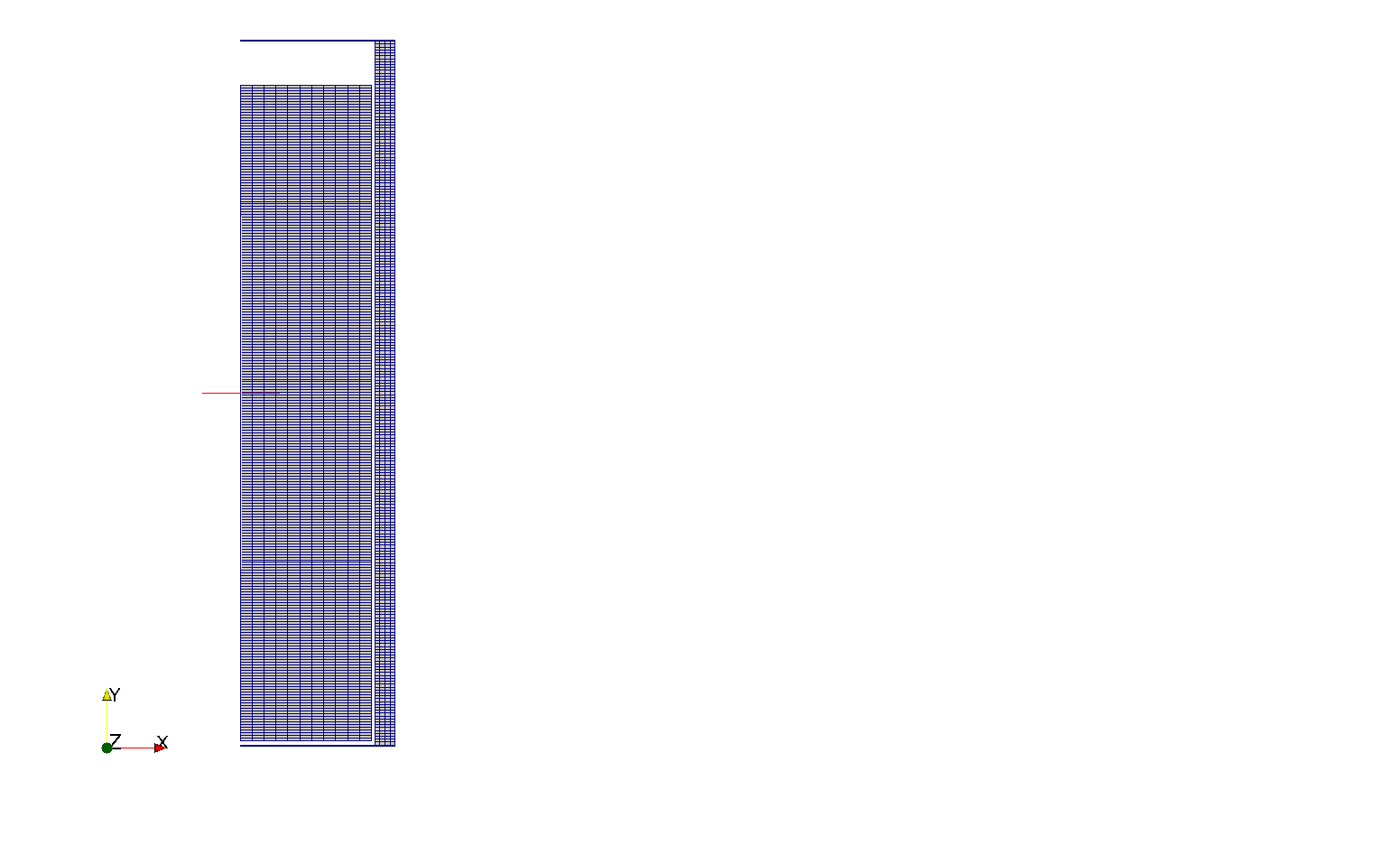
Figure 4: BN1/3 mesh

Figure 5: BN1/4 mesh

Figure 6: BN3/15 mesh
Input files
The BISON input and all supporting files (power histories, axial power profiles, etc.) for BN1/3, BN1/4 and BN3/15 are provided with the code distribution at bison/assessment/LWR/validation/Tribulation/analysis/BN1X3, bison/assessment/LWR/validation/Tribulation/analysis/BN1X4, and bison/assessment/LWR/validation/Tribulation/analysis/BN3X15, respectively.
Material and Behavioral Models
The following material and behavioral models for UO fuel were used:
UO2Thermal - NFIR: NFIR model for temperature and burnup dependent thermal properties
ComputeFiniteStrainElasticStress: elastic mechanical behavior
ComputeIsotropicElasticityTensor: Constant values are used for the Young's modulus ( Pa) and Poisson ratio ()
UO2RelocationEigenstrain: relocation strains, relocation activation threshold power set to 5 kW/m
ComputeThermalExpansionEigenstrain: thermal expansion with a constant instanteous thermal expansion coefficient
UO2VolumetricSwellingEigenstrain : volumetric expansion due to solid and gaseous swelling
UO2Sifgrs: fission gas release model used with the gaseous swelling model
UO2VolumetricSwellingEigenstrain(Pastore et al., 2015)
For the cladding material, a constant thermal conductivity of 16 W/m-K was used and both thermal and irradiation creep were considered using the Limback model (Limbäck and Andersson, 1996). The following material and thermal behavior models were used for the Zircaloy-4 cladding:
HeatConductionMaterial: Thermophysical material properties
ZryCreepLimbackHoppeUpdate and ZryElasticityTensor: mechanical creep and elastic deformation behavior for Zircaloy-4
ZryIrradiationGrowthEigenstrain: ESCORE model for volumetric swelling due to irradiation exposure
ZryThermalExpansionMATPROEigenstrain: thermal expansion of Zircaloy with the MATPRO model
Details and references for all of these models listed above can be found on the linked BISON documentation pages.
Results Comparison
Data from the TRIBULATION irradiation program was used to assess the code's capability to capture the integral fuel rod fission gas release, cladding creep down strain, fuel column changes, fuel rod growth, and rod internal void volume. A comparison of the predicted values from BISON calculations versus measured values from experimental data are shown in Table 4, Table 5, and Table 6 for BN1/3, BN1/4, and BN3/15 rods, respectively.
Table 4: BISON prediction versus measured data for BN1/3.
| BISON prediction | Measured Data | |
|---|---|---|
| Burnup (MWd/kgU) | 50.65 | 51.6 |
| Fission Gas Release () | 7.083 | 5.4 |
| Fuel column changes (mm) | 9.048 | 4.5 (Length Increase) |
| Final void volume (cc) | 4.36 | 6.46 |
| Fuel rod growth (mm) | 2.877 | 6.03 |
Table 5: BISON prediction versus measured data for BN1/4.
| BISON prediction | Measured Data | |
|---|---|---|
| Burnup (MWd/kgU) | 50.59 | 51.2 |
| Fission Gas Release | 8.335 | 5.5 |
| Fuel column changes (mm) | 8.915 | 3.9 (Length Increase) |
| Final void volume (cc) | 4.56 | 6.12 |
| Fuel rod growth (mm) | 2.997 | 4.86 |
Table 6: BISON prediction versus measured data for BN3/15.
| BISON prediction | Measured Data | |
|---|---|---|
| Burnup (MWd/kgU) | 50.66 | 51.1 |
| Fission Gas Release | 16.47 | 5.6 |
| Fuel column changes (mm) | 10.295 | 7.4 (Length Increase) |
| Final void volume (cc) | 4.43 | 6.02 |
| Fuel rod growth (mm) | 2.858 | 1.62 |
Fission Gas Release
The only fission gas release data available for this experiment is from destructive PIE puncture tests. Figure 7, Figure 8, and Figure 9 show BISON's comparisons with end-of-life measurement for the BN1/3, BN1/4, and BN3/15, respectively. BISON computes a reasonable FGR value that over predicts the measured results for BN1/3 and BN1/4 by a small margin. However, BISON over predicts the measured result for BN3/15 by a fairly large margin.
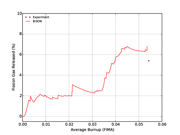
Figure 7: Fission gas release comparisons for BN1/3
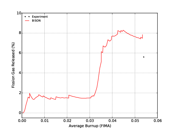
Figure 8: Fission gas release comparisons for BN1/4
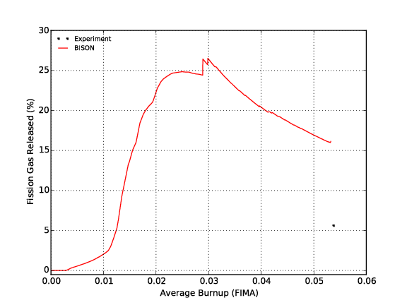
Figure 9: Fission gas release comparisons for BN3/15
Cladding Creep Down Strain
The calculated cladding creep down strain as a function of axial position is compared to measured data. The cladding creep down strain is calculated from the computed cladding diamter. Figure 10 shows comparisons of BISON computed results for BN1/3 to the measured cladding creep down strain data at the end of the first BR3 irradiation, after the BR2 transient, and at the end of the second BR3 irradiation. Reasonable cladding creep down strain values are computed at the end of the first BR3 irradiation and after the BR2 transient, but not at the end of the second BR3 irradiation. BISON strongly over predicts the cladding creep down strain toward the center of the fuel stack at the end of the second BR3 irradiation. Figure 11 shows comparisons of BISON computed results to measured cladding creep down strain data at the end of the first and second BR3 irradiation for BN1/4. Similar to the BN1/3 results, reasonable cladding creep down values at the end of the first BR3 irradiation are computed for BN1/4, but not at the end of the second BR3 irradiation. Figure 12 shows comparisons of BISON computed results to measured cladding creep down strain data at the end of the second BR3 irradiation for BN3/15. For BN3/15, BISON strongly over predicts the cladding creep down strain toward the center of the fuel stack at the end of the second BR3 irradiation.
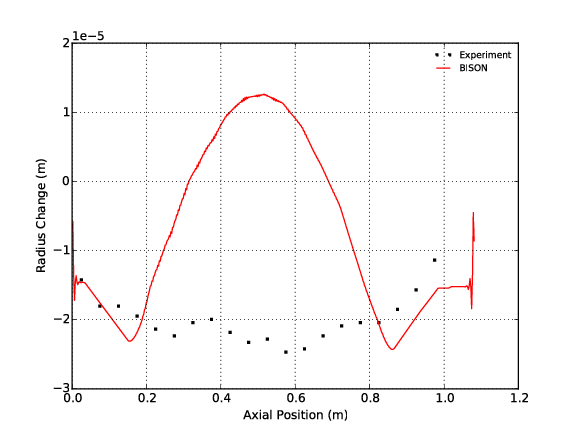
Figure 10: Cladding creep down strain comparisons for BN1/3
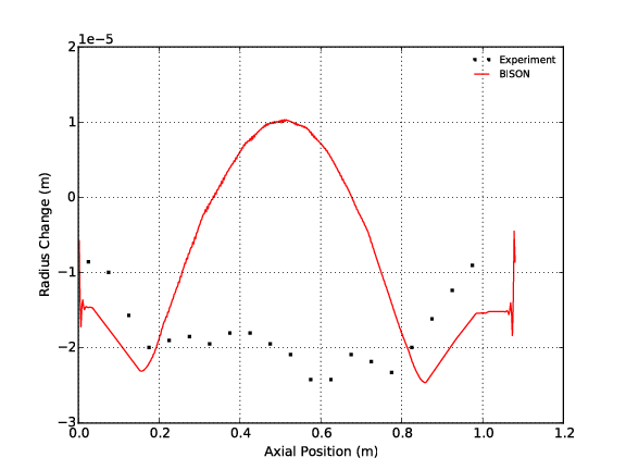
Figure 11: Cladding creep down strain comparisons for BN1/4
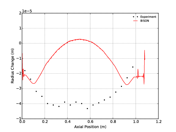
Figure 12: Cladding creep down strain comparisons for BN3/15
Discussion
Based on the data presented above, several observations can be made regarding the code execution and the results obtained from BISON analyses of the BN1/3, BN1/4, and BN3/15 test fuel rods.
Due to the low initial fill gas pressure for the BN3/15 rod, BISON experienced difficulty converging. The convergence issue appears to be related to fission gas release, rod internal pressure prediction and fuel/cladding contact behavior. Therefore, the PETSc option and time stepping controls were updated in the Executioner block to obtain convergence. The PETSc options selected for -pc_type and -pc_factor_mat_solver_package input is 'lu' and 'superlu_dist'. The timestep_limiting_function, max_function_change, and force_step_every_function_point options were not used. These updates resolve the convergence issues for the simulation of BN3/15 rod. However, this issue warrants further review for the analysis of rods with low initial fill gas pressure.
BISON over predicts the EOL FGR by a large margin for BN3/15 rod.
- From Figure 7, Figure 8 and Figure 9, sharp increases in FGR can be seen that correspond to large power drops. This rapid release of fission gas during power drop appears to be characteristic of the SIFGRs model implemented in BISON. This response may not be representative of FGR kinetics and warrants further review.
BISON over predicts the EOL cladding creep down strain for all three rods by a very large margin.
- Based on evaluation of these and other assessment cases, this behavior appears to be related to fuel swelling, especially affecting cladding creep down after fuel/cladding contact. Additionally, other effects on fuel deformation including relocation, densification, fuel creep, etc. The combined effect of these mechanisms could also influence the behavioral response seen in these analyses.
References
- IFPETD.
OECD Nuclear Energy Data Bank.
Technical Report, IFPE/Tribulation Database, May 2002.[BibTeX]
- M. Limbäck and T. Andersson.
A model for analysis of the effect of final annealing on the in- and out-of-reactor creep behavior of zircaloy cladding.
In Zirconium in the Nuclear Industry: Eleventh International Symposium, ASTM STP 1295, 448–468. 1996.[BibTeX]
- M. Lippens and D. Boulanger.
Tribulation international programme: final report.
Technical Report 89/79, BelgoNucleaire, September 1989.[BibTeX]
- G. Pastore, L.P. Swiler, J.D. Hales, S.R. Novascone, D.M. Perez, B.W. Spencer, L. Luzzi, P. Van Uffelen, and R.L. Williamson.
Uncertainty and sensitivity analysis of fission gas behavior in engineering-scale fuel modeling.
Journal of Nuclear Materials, 465:398–408, 2015.[BibTeX]