Riso GE7 Fuel Pin ZX115
Overview
The Riso-3 GE7 test is a bump test that was carried out during the third Riso Transient Fission Gas Release Project in 1989 (R, 1990). The fuel pin ZX115 was supplied by General Electric Company and was neither punctured nor re-fabrication prior to the test. The test pin was the lower middle segment of four approximately 0.975 m long segments assembled to a stringer. The fuel segment was base irradiated in the Quad Cities-1 boiling water reactor (BWR) over four reactor cycles. The bump test was performed in the water-cooled HP-1 rig under BWR conditions in the Riso DR3 test reactor.
Test Description
Rod Design Specifications
The rod specifications for the Riso-3 GE7 test is are summarized in Table 1.
Table 1: Riso-3 GE7 rod specifications.
| Fuel Rod | Measurement | Unit |
|---|---|---|
| Fuel stack height | 752.1 | mm |
| Nominal plenum height | 143.4 | mm |
| Fill gas composition | He | |
| Fill gas pressure | 0.29 | MPa |
| Fuel | Measurement | Unit |
| Material | UO | |
| Enrichment | 3.0 | |
| Density | 95.2 | |
| Outer diameter | 10.41 | mm |
| Pellet geometry | Chamfered | |
| Grain size | 11.3-12.8 | m |
| Grain radius | 9.04 | m |
| Pellet Chamfer (both ends) | Measurement | Unit |
| Dish diameter | - | cm |
| Dish depth | - | cm |
| Chamfer width | 0.18 | mm |
| Chamfer depth | 0.38 | mm |
| Cladding | Measurement | Unit |
| Material | Zr-2 | - |
| Outer diameter | 12.26 | mm |
| Inner diameter | 10.63 | mm |
| Wall thickness | 0.815 | mm |
Operating Conditions and Irradiation History
The base irradiation average power is shown in Figure 1. The average power during the ramp test is shown in Figure 2. The axial power profile is nearly linear for the base irradiation, however, during the ramp test, the power is shifted heavily to the bottom of the rod (see Figure 3). The clad surface temperature was input as a function, along with the fast neutron flux from data provided in the FUMEX-III data set (IAEA, 2008-2012). The coolant inlet temperature and pressure for the base irradiation and power ramp is shown in Table 2.
Table 2: Operational input parameters.
| Base Irradiation | Measurement | Unit |
|---|---|---|
| Coolant inlet temperature | 295 | C |
| Coolant pressure | 7.24 | MPa |
| Power Ramps | Measurement | Unit |
| Coolant inlet temperature | 289 | C |
| Coolant pressure | 7.24 | MPa |
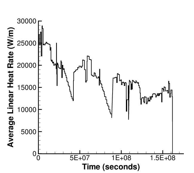
Figure 1: Base irradiation average power history for test pin ZX115.
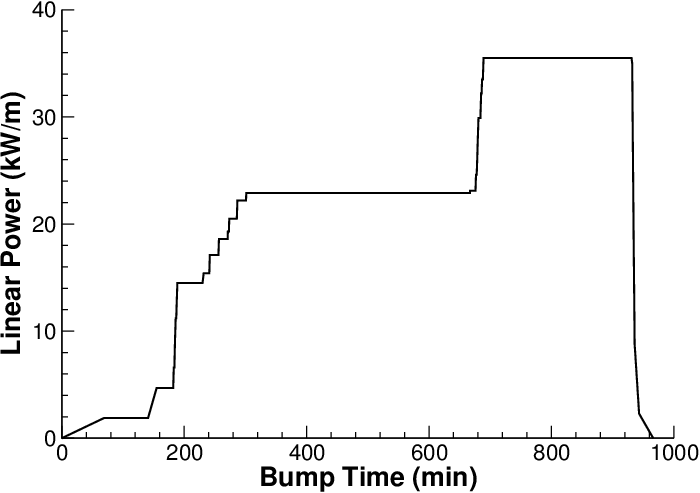
Figure 2: Average power history during power ramp. Note: The time has been zeroed to the start of the ramp.
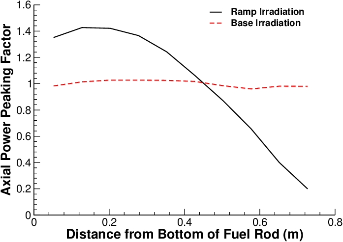
Figure 3: Axial power profile during base irradiation and ramp test.
Model Description
Geometry and Mesh
The Riso GE7 ZX115 rod was modeled both as a smeared fuel pellet stack and as a discrete fuel pellet stack. The geometric parameters specified in Table 1 were used to create the meshes for these simulations. The smeared fuel was meshed as a single smeared fuel column with 11 radial elements and 432 axial elements. The discrete fuel was meshed as 72 individual pellets, each with 8 axial and 11 radial elements. Figure 4 shows a section of the mesh with a stress contour plot. This contour plot was made near the end of the run. Actual numbers are irrelevant in this case as this plot is only meant to show the discretization.
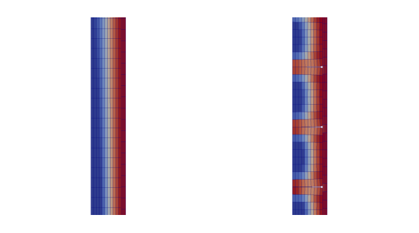
Figure 4: A section of the GE7 ZX115 fuel rod mesh with a temperature contour plot.
Input files
The BISON input and all supporting files (power histories, axial power profile, fast neutron flux history, etc.) for this case are provided with the code distribution at bison/assessment/LWR/validation/ and bison/assessment/LWR/validation/Riso_GE7_ZX115/analysis.
To avoid code duplication, the input files are structured in this format: A first base input file contains characteristics common to all the Riso cases: Riso_Base.i. A second base input file contains characteristics common to all the Riso case that do not use the action: Riso_Base_sub.i. Input files containing information specific to the fuel rod and the type of problem solving use the !include function to build a complete input file with the base files.
To run a specific assessment, such as the Riso GE7 ZX115, run: Riso_GE7_ZX115.i.
Elastic Fuel: Material and Behavioral Models
The following material and behavioral models for the fuel were used:
UO2Thermal - NFIR: NFIR model for temperature and burnup dependent thermal properties
ComputeFiniteStrainElasticStress and UO2ElasticityTensor: elastic mechanical behavior
UO2RelocationEigenstrain: relocation strains, relocation activation threshold power set to 5 kW/m
ComputeThermalExpansionEigenstrain: thermal expansion with a constant instantaneous thermal expansion coefficient
UO2VolumetricSwellingEigenstrain: volumetric expansion due to solid and gaseous swelling
UO2Sifgrs: fission gas release model used with the gaseous swelling model
UO2VolumetricSwellingEigenstrain(Pastore et al., 2015)
Both thermal (primary and secondary creep) and irradiation creep were considered to simulate rapid cladding deformation during power ramps.The following material and thermal behavior models were used for the cladding:
HeatConductionMaterial: Thermophysical material properties
ZryCreepLimbackHoppeUpdate and ZryElasticityTensor: mechanical creep and elastic deformation behavior
ZryIrradiationGrowthEigenstrain: ESCORE model for volumetric swelling due to irradiation exposure
ZryThermalExpansionMATPROEigenstrain: thermal expansion of Zircaloy with the MATPRO model
Details and references for all of these models listed above can be found on the linked BISON documentation pages.
Results Comparison
Clad Diameter
A comparison of the predicted and measured rod outer diameter at post ramp is shown in Figure 5. The ramp test for this experiment had a strong axial power profile by design originating two well defined displacement regions. The lower segment saw the pin peak power with a dominant effect exercised by thermal expansion and swelling that lead to positive displacements. On the contrary the upper part, where the cladding creep down is the prevalent phenomenon, is characterized by a decreased outer diameter. The BISON calculation clearly underestimated the radius change along the axial position, a trend connected to the value set for the initial 3D grain radius value used in the fission gas model.
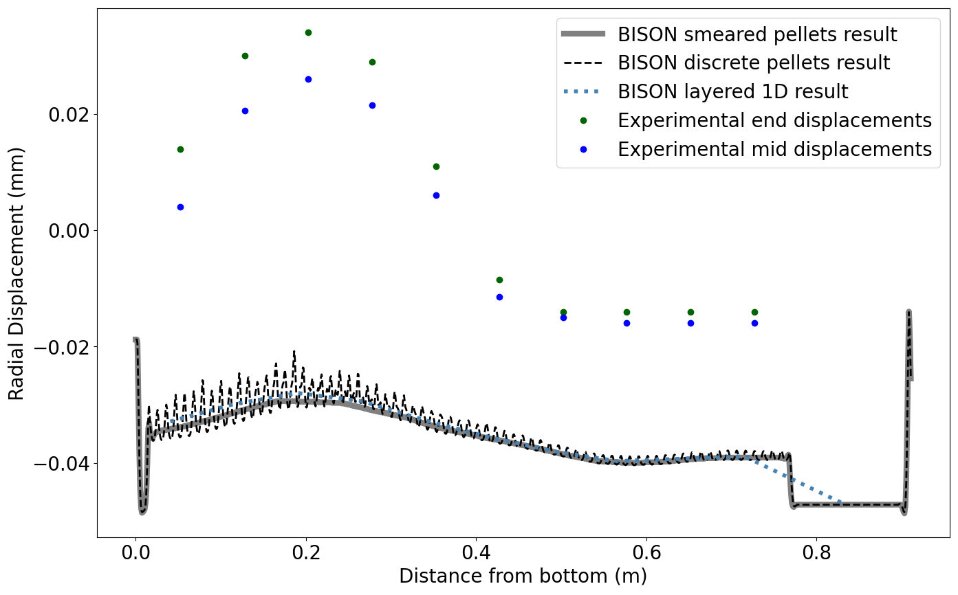
Figure 5: Comparison of experimental and calculated cladding outer displacements after bump test.
Other Results
The Riso GE7 experiment was centered around fuel rod diameter, but other quantities were measured as well. Figure 6 plots the fuel centerline temperature of the smeared pellet simulation against the discrete pellet model. The plot shows that the two models compare very closely with the discrete pellet having a slightly higher temperature in the ramp.
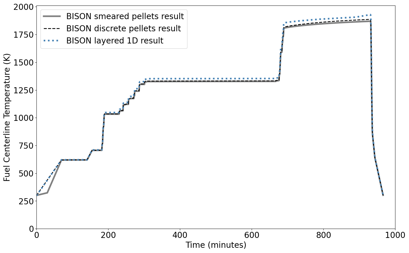
Figure 6: Comparison of the BISON calculated fuel centerline temperature on the smeared and discrete pellet meshes during and after the power ramp.
Figure 7 shows the fission gas released percentage, that represents the quantity of gas released over the total fission gas produced in the fuel. The measured results were taken at the end of the ramp test by fuel pin puncturing. Both the smeared and the discrete models compare well to the measured results. The discrete compares better with slightly more fission gas release and this is due to the higher temperature the discrete pellets saw.
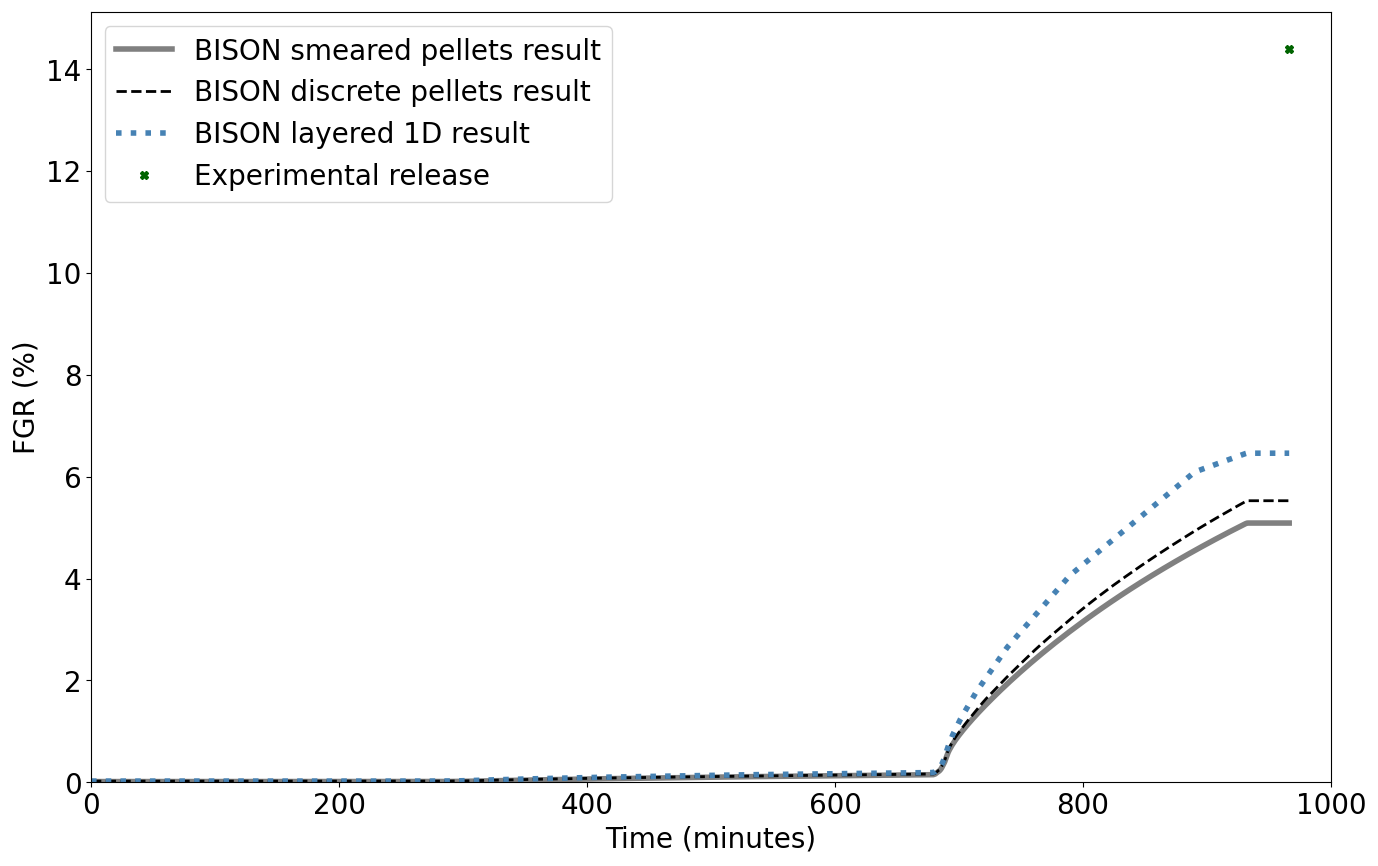
Figure 7: Comparison of the BISON calculated fission gas release percentage with the Riso GE7 experiment measurement from the bump test power ramp.
Figure 8 plots the plenum pressure of the test. Once again the smeared and the discrete models compare well to the post ramp puncturing result. The discrete model shows a higher internal pressure during the ramp caused by the combination of higher temperature and increased fission gas release.
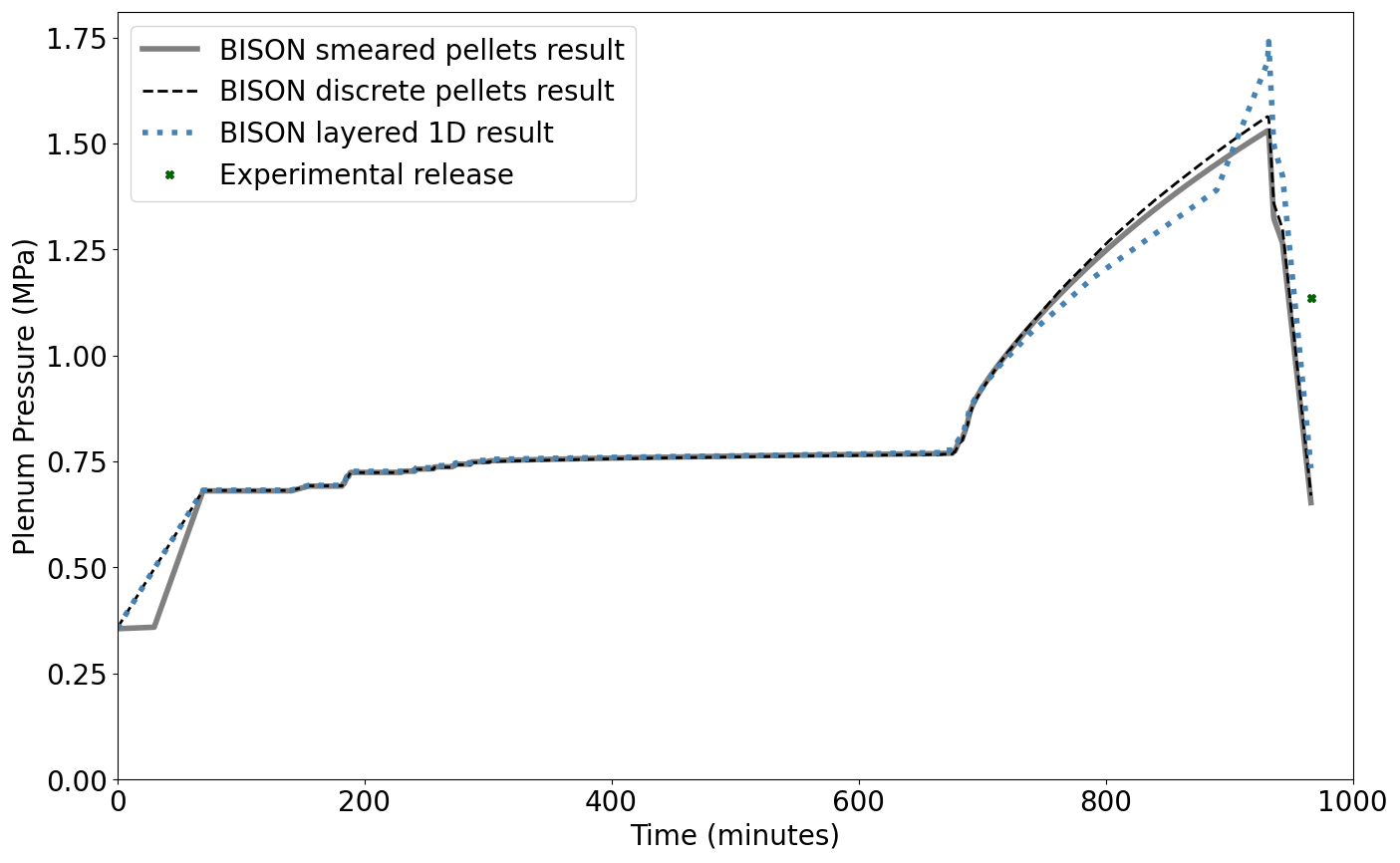
Figure 8: Comparison of the Riso GE7 experiment measurement and the BISON calculated plenum pressure, on the smeared and discrete pellet meshes, during and after the power ramp.
Figure 9 plots the internal gas volume of the rod. The smeared and discrete cases follow each other until the start of the high power ramp, with a difference that corresponds to the volume of the chamfers in the discrete pellet mesh. Possible explanations for the difference in the smeared and discrete meshes after the high power ramp include the following: As the temperature rises, the fuel stack volume increases due to thermal expansion and fuel swelling, causing a gas volume decrease. Shortly after the start of the ramp, the smeared and discrete cased diverge and the discrete gains volume. This increase in the volume in the discrete pellet mesh may be caused by the thermal expansion dominating and opening the gap between the pellets. This thermal expansion also starts to cause the bamboo effect on the cladding as it creeps down. The gaps opening and possible clad lift due to bambooing could account for the gas volume increase. It should be noted that the abrupt down spike at the end of the run is from a numerical error. The end results for free gas volume are over estimated.
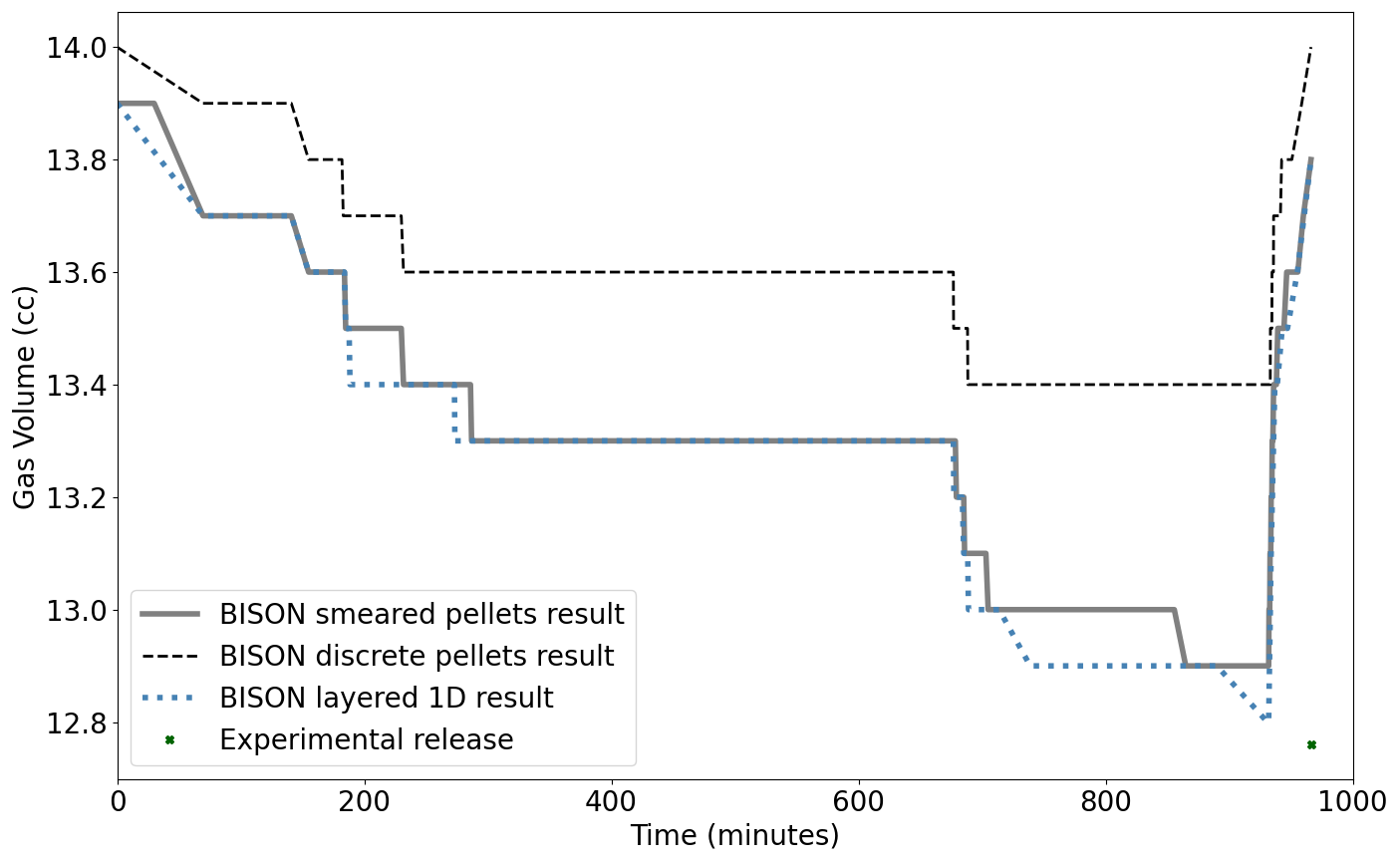
Figure 9: BISON and Riso GE7 results for free gas volume during and after the power ramp. The difference in the free gas volume between the smeared and discrete pellets at the start of the power ramp can be attributed to the prescence of the chamfers in the discrete pellet mesh.
Discussion
From the results shown above it can be seen that BISON over predicts the cladding creep down due to the coolant pressure. Going into this experiment there were a couple assumptions made that would have affected the outcome of the diameter. Cladding oxidation was omitted and this implies that BISON should always under predict the rod diameter. The fuel was modeled as elastic and there was no frictional contact between the fuel and cladding. Both of these would have changed the overall results of this simulation. As mentioned in the previous section both smeared and discrete post ramp FGR, plenum pressure and gas volume compare to each other and to the measured results. As new methods are implemented in to BISON this simulation will be revisited.
Inelastic Fuel: Material and Behavioral Models
Inelastic modeling aims at reproducing the plastic behavior of the fuel during irradiation. It takes into account additional physics modules and in this case fuel cracking and fuel creep was assessed.
The following material and behavioral models for UO fuel were used:
UO2Thermal - NFIR: NFIR model for temperature and burnup dependent thermal properties
ComputeSmearedCrackingStress: inelastic mechanical behavior
PowerLawSoftening: softening model with an abrupt stress release upon cracking
UO2CreepUpdate: calculates the secondary thermal and irradiation creep for UO2 LWR fuel
ComputeIsotropicElasticityTensor: constant values are used for the two elastic constants Young's modulus ( Pa) and Poisson ratio ()
UO2RelocationEigenstrain: relocation strains, relocation activation threshold power set to 5 kW/m
ComputeThermalExpansionEigenstrain: thermal expansion with a constant instantaneous thermal expansion coefficient
UO2VolumetricSwellingEigenstrain: volumetric expansion due to solid and gaseous swelling
UO2Sifgrs: fission gas release model used with the gaseous swelling model
UO2VolumetricSwellingEigenstrain(Pastore et al., 2015)
Both thermal (primary and secondary creep) and irradiation creep were considered to simulate rapid cladding deformation during power ramps.The following material and thermal behavior models were used for the cladding:
HeatConductionMaterial: Thermophysical material properties
ZryCreepLimbackHoppeUpdate and ZryElasticityTensor: mechanical creep and elastic deformation behavior
ZryIrradiationGrowthEigenstrain: ESCORE model for volumetric swelling due to irradiation exposure
ZryThermalExpansionMATPROEigenstrain: thermal expansion of Zircaloy with the MATPRO model
Details and references for all of these models listed above can be found on the linked BISON documentation pages.
Results Comparison
The results presented in this section show comparisons between inelastic calculations, and experimental results. The simulation was derived taking into account a smeared fuel pellet stack. For this case an updated input file version was adopted.
Clad Diameter
As mentioned, the parameter of main interest in the frame of Riso GE7 experiment was the cladding outer diameter. Figure 10 plots the results obtained against the experimental rod measurement after bump test. An overall improvement was achieved: inelastic simulation well predict the radial changes along the axial position of the fuel pin. As one can notice the implementation of additional plastic modules allowed a more accurate estimation, in particular along the peaked power segment.
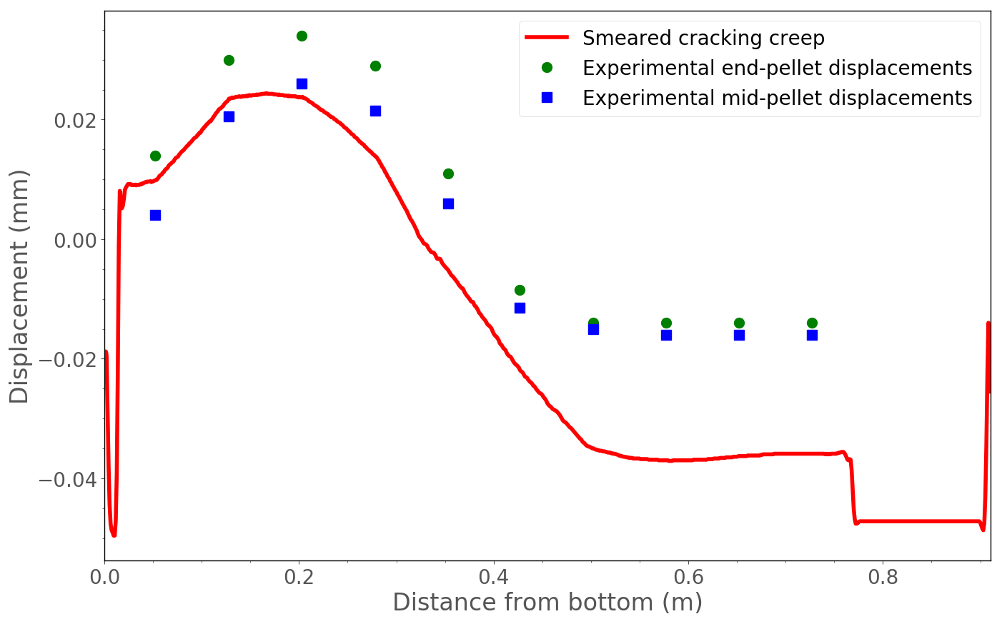
Figure 10: Comparison of experimental and calculated cladding outer displacements after bump test.
Other Results
Other than the cladding diameter, the fission gas release was another quantity of interest. Figure 11 compares the experimental puncturing results against the calculations. Despite the improvement pursued in the thermo-mechanical modeling, a sensible worsening of the fission gas release estimation was obtained. A possible explanation can be found in the updated input file parameters. Indeed, the initial grain size was adjusted to a greater value that, as expected, strongly influenced the amount of fission gas released.
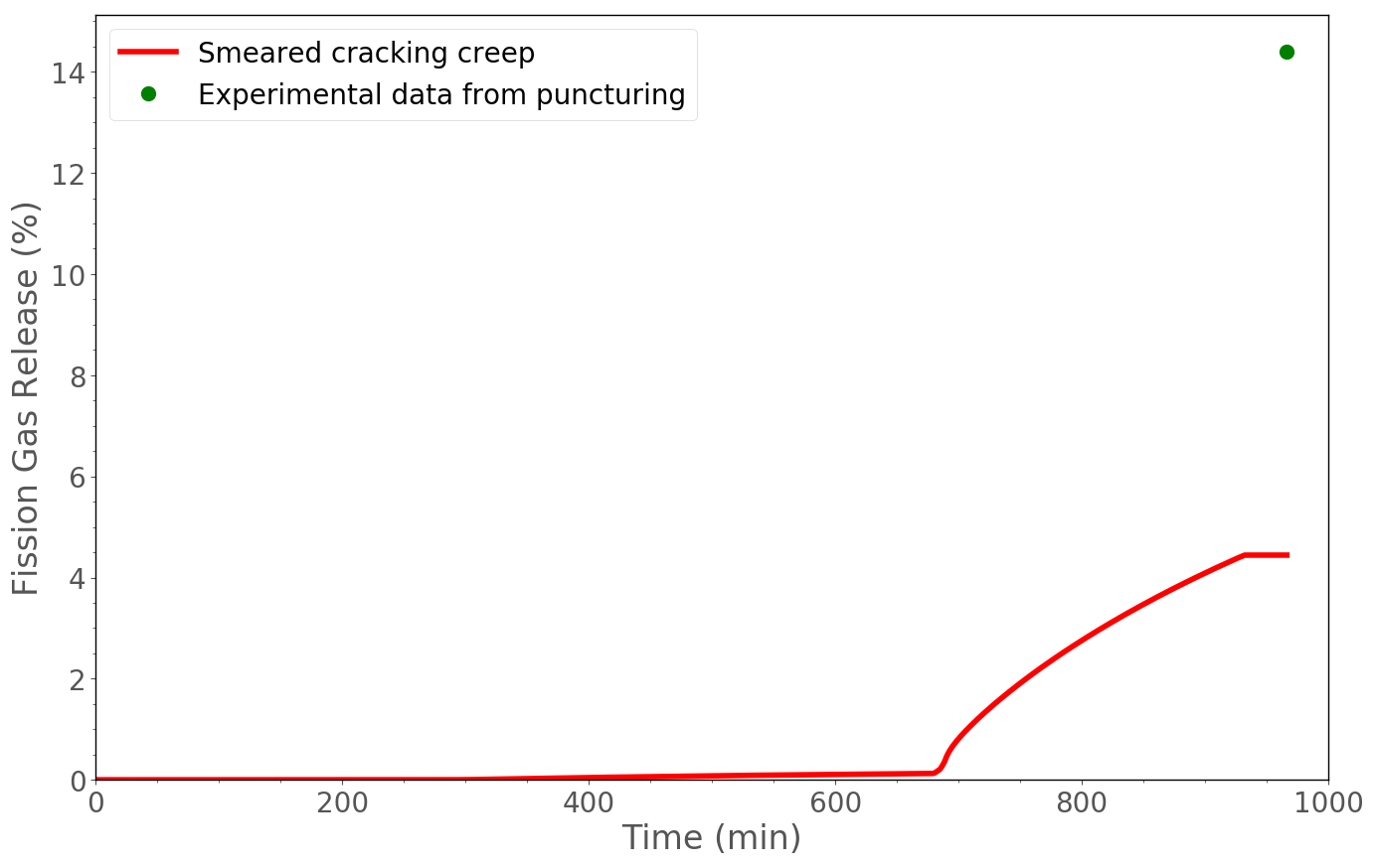
Figure 11: Comparison of experimental puncturing and calculated fission gas released percentage during power bump.
Discussion
A significant step forward in predicting the thermo-mechanical behavior of the fuel pin was achieved. It is important to remark that the addition of fuel plastic behavior models in BISON allowed a further improvement, adding complexity and realism to the simulations. The same assumptions explained in the previous paragraph were considered. Concerning the fission gas release, a dedicated assessment could help improve fission gas behavior estimation.
References
- IAEA.
Improvement of Computer Codes Used for Fuel Behaviour Simulation (FUMEX-III): Report of a Coordinated Research Project 2008-2012.
Technical Report IAEA-TECDOC-1697, International Atomic Energy Agency, 2008-2012.[BibTeX]
- G. Pastore, L.P. Swiler, J.D. Hales, S.R. Novascone, D.M. Perez, B.W. Spencer, L. Luzzi, P. Van Uffelen, and R.L. Williamson.
Uncertainty and sensitivity analysis of fission gas behavior in engineering-scale fuel modeling.
Journal of Nuclear Materials, 465:398–408, 2015.[BibTeX]
- R.
The Third Risø Fission Gas Project: Bump Test GE7 (ZX115).
Technical Report Risø-FGP3-GE7, Risø, September 1990.[BibTeX]