Riso AN3
Overview
The Riso AN3 experiment conducted at the Riso DR3 water-cooled HP1 rig utilized a re-fabricated rod from the Biblis A pressurized water reactor (PWR) (IAEA, 2002-2007),(R, 1990). The mother rod, CB8, was irradiated over four reactor cycles up to about 41 GWd/t, and re-fabricated to a shorter length. The re-fabricated rod, CB8-2R, was instrumented with a fuel centerline thermocouple and a pressure transducer. The fuel centerline temperature, fission gas release and rod internal pressure can be used for comparison.
BISON time domain results on this page have not been updated to reflect the latest modeling and simulation formulations.
Test Description
Rod Design Specifications
Rod CB8-2R was a re-fabricated rod extracted from a full length rod. The hole for the thermocouple was at the top of the fuel rod and did not penetrate the entire fuel stack. The re-fabricated rod geometry is tabulated in Table 1.
Table 1: Riso AN3 Test Rod Specifications
| Fuel Rod | Measurement | Unit |
|---|---|---|
| Overall length | 0.39058 | m |
| Fuel stack height | 0.286 | m |
| Nominal plenum height | 61.0 | mm |
| Mother Rod | Measurement | Unit |
| Fill gas composition | He | |
| Fill gas pressure | 2.31 | MPa |
| Re-Fabricated Rod | Measurement | Unit |
| Fill gas composition | He | |
| Fill gas pressure | 1.57 | MPa |
| Fuel | Measurement | Unit |
| Material | UO | |
| Enrichment | 2.95 | |
| Density | 93.74 | |
| Inner diameter | 2.5 | mm |
| Outer diameter | 9.053 | mm |
| Pellet geometry | both ends | |
| Grain diameter | 6.0 | m |
| Pellet Dishing | Measurement | Unit |
| Dish diameter | 0.665 | cm |
| Dish depth | 0.013 | cm |
| Chamfer width | 0.046 | cm |
| Chamfer depth | 0.016 | cm |
| Cladding | Measurement | Unit |
| Material | Zr-4 | |
| Outer diameter | 10.81 | mm |
| Inner diameter | 9.258 | mm |
| Wall thickness | 0.776 | mm |
Operating Conditions and Irradiation History
The power history for the base irradiation carried out at the Biblis A PWR is shown in Figure 1. The experiment power history carried out at the Riso DR3 facility is shown in Figure 2. A prescribed axial profile for this experiment was provided in the FUMEX-II data (IAEA, 2002-2007). The measured clad surface temperature as a function of time was also provided in the FUMEX-II data (IAEA, 2002-2007) and used as a boundary condition for this simulation. The other reactor operation parameters are tabulated in Table 2.
Table 2: Operational input parameters.
| Base Irradiation | ||
|---|---|---|
| Coolant inlet temperature | 287.7 | C |
| Coolant pressure | 15.52 | MPa |
| Fast neutron flux | 3.4 | n/(cms) per (kW/m) |
| Power Ramps | ||
| Coolant inlet temperature | n/a | C |
| Coolant pressure | 15.3 | MPa |
| Fast neutron flux | 4.0 | n/(cms) per (kW/m) |
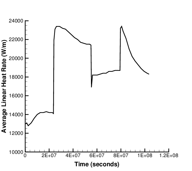
Figure 1: Base irradiation history for fuel segment CB8, carried out at Biblis A PWR.
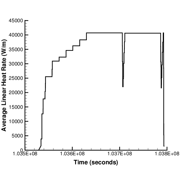
Figure 2: Riso DR3 irradiation period for test AN3 (CB8-2R).
Model Description
Geometry and Mesh
The re-fabricated rod geometry was modeled for the entire simulation considering a smeared column of flat ended pellets, with the top pellets containing the hole for the thermocouple. The plenum height was adjusted such that the plenum volume at the beginning of the bump test was approximately 7.0 cm. The entire fuel stack was shifted up from the bottom of the clad by 5.1 mm, which is the height of the insulator pellet at the bottom of the fuel rod.
A 2-dimensional axisymmetric quadratic (Quad8 elements) mesh was used to model the geometry of the rod used in the AN3 experiment. The fuel was meshed considering two fuel pellet types. The first pellet type was 4.1 cm in length with a hole down the center, the second pellet type was 24.5 cm in length with no hole down the center. The first pellet type's mesh consisted of 29 axial nodes and 10 radial nodes (for an aspect ratio of 4.07). The second pellet type's mesh consisted of 166 axial nodes and 13 radial nodes (for an aspect ratio of 3.93). The clad mesh consisted of 131 axial nodes and 3 radial nodes.
Input files
The BISON input and all supporting files (power histories, axial power profile, fast neutron flux history, etc.) for this case are provided with the code distribution at bison/assessment/LWR/validation/ and bison/assessment/LWR/validation/Riso_AN3/analysis.
To avoid code duplication, the input files are structured in this format: A first base input file contains characteristics common to all the Riso cases: Riso_Base.i. A second base input file contains characteristics common to all the Riso case that do not use the action: Riso_Base_sub.i. Input files containing information specific to the fuel rod and the type of problem solving use the !include function to build a complete input file with the base files.
To run a specific assessment, such as the Riso AN3, run: Riso_AN3.i.
Material and Behavioral Models
The following material and behavioral models for UO fuel were used:
UO2Thermal - NFIR: NFIR model for temperature and burnup dependent thermal properties
ComputeFiniteStrainElasticStress and UO2ElasticityTensor: elastic mechanical behavior
UO2RelocationEigenstrain: relocation strains, relocation activation threshold power set to 5 kW/m
ComputeThermalExpansionEigenstrain: thermal expansion with a constant instantaneous thermal expansion coefficient
UO2VolumetricSwellingEigenstrain : volumetric expansion due to solid and gaseous swelling
UO2Sifgrs: fission gas release model used with the gaseous swelling model
UO2VolumetricSwellingEigenstrain(Pastore et al., 2015)
For the cladding material, a constant thermal conductivity of 16 W/m-K was used and both thermal and irradiation creep were considered using the Limback model (Limbäck and Andersson, 1996). The following material and thermal behavior models were used for the Zircaloy-4 cladding:
HeatConductionMaterial: Thermophysical material properties
ZryCreepLimbackHoppeUpdate and ZryElasticityTensor: mechanical creep and elastic deformation behavior for Zircaloy-4
ZryIrradiationGrowthEigenstrain: ESCORE model for volumetric swelling due to irradiation exposure
ComputeThermalExpansionEigenstrain: thermal expansion with a constant instantaneous thermal expansion coefficient
Details and references for all of these models listed above can be found on the linked BISON documentation pages.
Boundary and Operating Conditions
The Riso DR3 irradiation period for the AN3 test shown in Figure 2 was appended to the base irradiation power history shown in Figure 1. It was assumed that the clad temperature during the down time between base irradiation and the Riso test was 500K. The fast neutron flux was input as a function of power and scaled to 4.9e17.
Results Comparison
The Riso AN3 experiment is used to assess the code's capability to capture the fuel centerline temperature and the integral fuel rod fission gas release. Fuel centerline temperature and fission gas release data from the TRANSURANUS and ENIGMA codes were digitized from the FUMEX-II report (Killeen et al., 2007) for comparison with the BISON predictions.
Temperature
BISON predicts the fuel centerline temperature well (Figure 3) and is comparable with other well known fuel performance codes. The fuel centerline temperature is taken at a node approximately 36.4 mm from the top of the fuel stack.
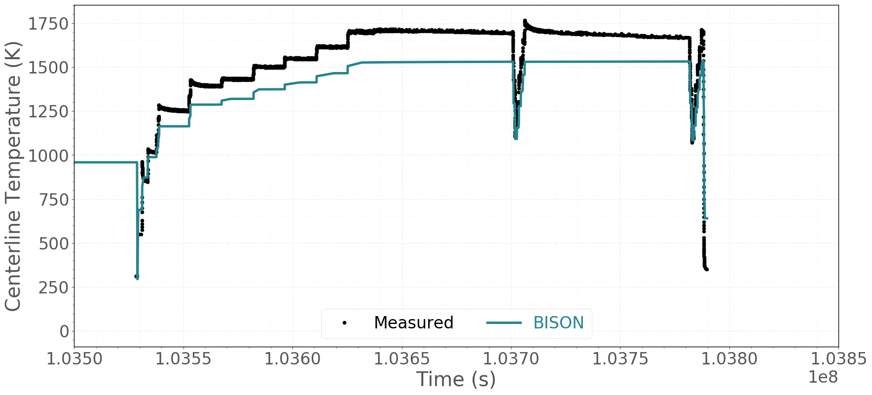
Figure 3: BISON fuel centerline temperature comparison to Riso experimental data.
Fission Gas Release
The calculated integral fuel rod fission gas release is compared to the measured data, as well as with the TRANSURANUS and ENIGMA predictions, in Figure 4. In view of the uncertainties involved in FGR modeling, the predictive accuracy is satisfactory. When compared to other codes, BISON's prediction of total FGR is excellent, with many codes underpredicting the fission gas release at the end of life by more than a factor of 2 (Killeen et al., 2007).
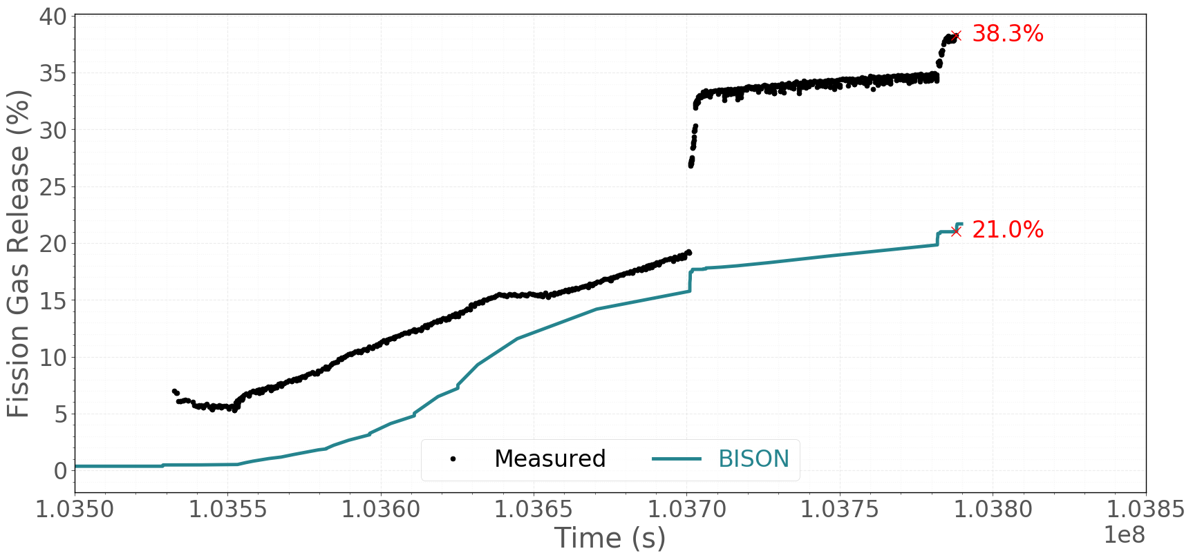
Figure 4: BISON total fission gas release comparison to Riso experimental data.
Rod Internal Pressure
The fission gas release as a function of time during the ramp test is calculated based off the measured pressure of the rod. When compared to the measured rod internal pressure, BISON slightly over predicts the rod pressure (Figure 5). This is likely due to the conditions of the rod at the refabrication time. It is reported that the fill gas is measured at room temperature, however, the temperature of the gap is higher than that of ambient temperature due to the decay heat of the already irradiated fuel.
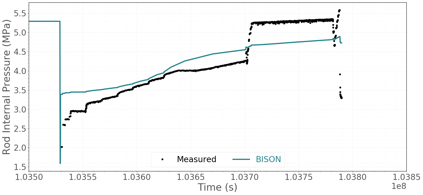
Figure 5: BISON rod internal pressure comparison to Riso measured data.
References
- IAEA.
Fuel Modelling at Extened Burnup (FUMEX-II): Report of a Coordinated Research Project 2002-2007.
Technical Report IAEA-TECDOC-1687, International Atomic Energy Agency, 2002-2007.[BibTeX]
- J. C. Killeen, J. A. Turnbull, and E. Sartori.
Fuel modelling at extended burnup: IAEA coordinated research project FUMEX-II.
In Proceedings of the 2007 International LWR Fuel Performance Meeting. San Francisco, California, Paper 1102, September 30-October 3 2007.[BibTeX]
- M. Limbäck and T. Andersson.
A model for analysis of the effect of final annealing on the in- and out-of-reactor creep behavior of zircaloy cladding.
In Zirconium in the Nuclear Industry: Eleventh International Symposium, ASTM STP 1295, 448–468. 1996.[BibTeX]
- G. Pastore, L.P. Swiler, J.D. Hales, S.R. Novascone, D.M. Perez, B.W. Spencer, L. Luzzi, P. Van Uffelen, and R.L. Williamson.
Uncertainty and sensitivity analysis of fission gas behavior in engineering-scale fuel modeling.
Journal of Nuclear Materials, 465:398–408, 2015.[BibTeX]
- R.
The Third Risø Fission Gas Project: Bump Test AN3 (CB8-2R).
Technical Report Risø-FGP3-AN3, Risø, September 1990.[BibTeX]