RE Ginna Rodlet-2 and Rodlet-4
Overview
The objective of the Siemens Power Corporation (SPC)- R. E. Ginna fuel irradiation program was to test proposed fuel designs with increased margin to PCI failure and potential for higher burnup. The lead fuel assemblies were fabricated by Exxon Nuclear Company (ENC, later acquired as SPC) under a cooperative program jointly sponsored by Empire State Electric Energy Research Corporation (ESEERCo), Rochester Gas and Electric Corporation (RG&E), and ENC (Packard, 1986). The irradiation program conducted at the R. E. Ginna nuclear power plant evaluated 14x14 fuel rod designs with both full length and segmented test rods featuring annular or solid pellets combined with standard (CWSRA Zr-4) or Zr-barrier (Zr-lined, CWSRA Zr-4) cladding. For the purposes of this fuel analysis problem, two rodlets from a segmented fuel rod in lead fuel assembly XT03 were evaluated: one with solid pellets and one with annular pellets. Both rods used standard cladding without a Zr-barrier. This experiment was chosen for analysis because of the availability of measured data for evaluation of several fuel rod performance characteristics including fission gas release, cladding hydrogen pick-up fraction, fuel column length changes, and end-of-life internal free volume and rod internal pressure.
Test Description
Rod Design Specifications
Two segmented rodlets from lead test assembly XT03 were chosen for analysis: Rodlet-2 type SSN5 and Rodlet-4 type ASN5. The fuel rodlet cross reference identification data is shown below in Table 1 (Corporation, 1997). The geometric input parameters for the R.E. Ginna Rodlet-2 and Rodlet-4 test are summarized in Table 2.
Table 1: R.E. Ginna Fuel Rodlet Cross Reference
| Rodlet Number | Assembly | Rod Position | Rod Serial Number | Segment Number | Segment Serial No. | Rodlet Type |
|---|---|---|---|---|---|---|
| 2 | XT03 | M07 | XV00-2604 | 3 | S003L | SSN5 |
| 4 | XT03 | L02 | XU10-2303 | 2 | S015U | ASN5 |
Table 2: R. E. Ginna Rodlet-2 and Rodlet-4 Test Rod Specifications.
| Fuel Rod | Measure | Unit |
|---|---|---|
| Overall length | 0.653 | m |
| Fuel stack height | 0.5418 | m |
| Nominal plenum height | 70.8 | mm |
| Fill gas composition | He | |
| Fill gas pressure | 2.1 | MPa |
| Fuel | Measure | Unit |
| Material | UO | |
| Enrichment (Rodlet-2) | 3.52 | |
| Enrichment (Rodlet-4) | 3.7 | |
| Density | 94 | |
| Inner diameter (Rodlet-4 only) | 2.814 | mm |
| Outer diameter | 8.903 | mm |
| Nominal diametral gap | 190 | m |
| Average grain size (Rodlet-2) | 22 | m |
| Average grain size (Rodlet-4) | 20 | m |
| Cladding | Measure | Unit |
| Material | Zr-4 | |
| Outer diameter | 10.592 | mm |
| Inner diameter | 9.093 | mm |
| Wall thickness | 0.749 | mm |
Operating Conditions and Irradiation History
The XT03 segmented rod was irradiated for 5 cycles in the R.E Ginna reactor to a final discharge average assembly burnup of 52.07 MWd/kgU. The reactor operated at or near full power throughout the five cycles of irradiation. The power mode selected is PiecewiseLinear. The power histories for Rodlet-2 and Rodlet-4 are shown in Figure 1 and Figure 2, respectively. These two power histories assumed a 24 hour startup time to reach full power, and a ramp rate of 0.33 kW/m/hr for large power increases. The ramp rate of 0.33 kW/m/hr was applied for Rodlet-2 at time step 18 to increase linear power from 21700 W/m to 33200 W/m in 125454.4 seconds and at time step 74 to increase linear power from 8200 W/m to 21300 W/m in 142909.1 seconds. The ramp rate was also applied for Rodlet-4 at time step 16 to go from LHGR of 16200 W/m to 33200 W/m in 185454.5 seconds and at time step 97 to go from 12600 W/m to 21400 W/m in 96000 seconds.
The startup times and ramp rates selected are based on ANATECH's experience with fuel rod modeling for steady state operation and are intended to minimize the introduction of computational artifacts from unrealistic power changes and ramp rates into the analyses . The ramp rate guidelines for typical power maneuvers are shown in Table 3. The axial profile was calculated from the SPC-RE-Ginna data package (OECDNEDB, 2002). The measured cladding outer surface temperature as a function of time was also provided in the SPC- RE-Ginna data package (OECDNEDB, 2002) and was used as a boundary condition for these simulations. The cladding outer surface temperature ranged from 568 K to 601.2 K. The initial fill-gas (Helium) pressure was 2.1 MPa, and the coolant system pressure was corrected to be 15.51 MPa instead of 155.1 MPa as shown in the QA report for SPC Irradiation in RE Ginna Reactor data (Giurgiuman and Wickersham, 1994). The fast neutron flux as a function time was calculated from the fluence data provided in the SPC-RE- Ginna data package (OECDNEDB, 2002). The fast neutron flux profile was scaled to 4.8e17. Operational input parameters are summarized in Table 4.
Table 3: Ramp Rate Guidelines for typical power maneuvers
| Steady State Operation | kW/ft/hr | kW/m/hr |
|---|---|---|
| Typical operating maneuvers | 0.1 | 0.33 |
| Start-Ups | 0.3 - 1.0 | 1.0 - 3.3 |
| Fast Transients | ||
| LOCA tests | 2.2E3 | 7.2E3 |
Table 4: Operational input parameters
| Base Irradiation | ||
|---|---|---|
| Coolant inlet temperature | K | 550.15 |
| Coolant pressure | MPa | 15.51 |
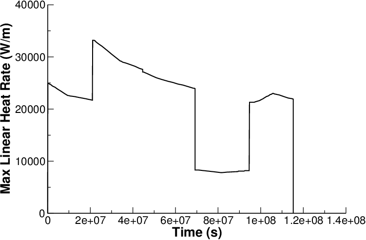
Figure 1: Rodlet-2 power history with 24 hours startup and ramp rate of 0.33 kW/m/hr
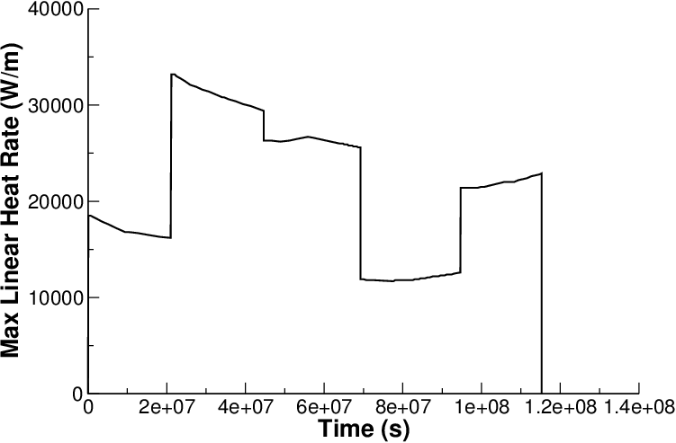
Figure 2: Rodlet-4 power history with 24 hours startup and ramp rate of 0.33 kW/m/hr
Model Description
Geometry and Mesh
The rod specifications in Table 2 were used to define the geometry for these simulations. Each rodlet was modeled as a 2-dimensional axi-symmetric linear mesh with quadratic elements. The Rodlet-2 fuel mesh consisted of 102 axial elements and 11 radial elements, whereas the Rodlet-4 fuel mesh consisted of 102 axial elements and 8 radial elements due to the presence of the fuel pellet annulus. The cladding mesh for both rodlets consisted of 4 radial elements.
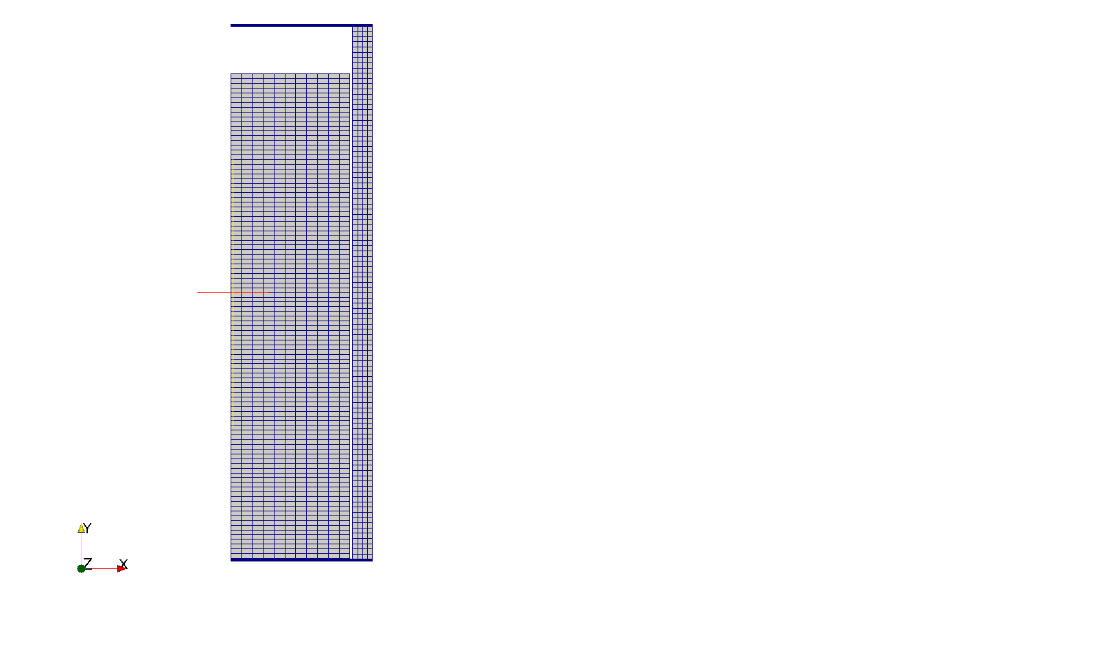
Figure 3: Rodlet-2 mesh
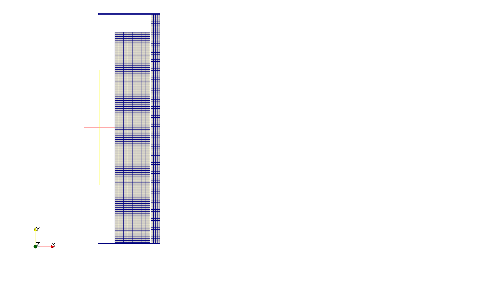
Figure 4: Rodlet-4 mesh
In order to accurately model the fuel rod initial free volume, the overall fuel rod length and upper plenum height were adjusted during the mesh generation to account for the volume of the plenum spring which is not explicitly modeled. The overall fuel rod lengths for Rodlet-2 and Rodlet-4 were reduced from 653 mm to 600.853 mm and 593.578 mm, respectively. The plenum heights for Rodlet-2 and Rodlet-4 were reduced from 70.8 mm to 53.59 mm and 46.316 mm, respectively. The meshes for each rodlet are shown in Figure 3 and Figure 4.
Input files
The BISON input and all supporting files (power histories, axial power profile, etc.) for Rodlet-2 and Rodlet-4 are provided with the code distribution at bison/assessment/LWR/validation/RE_Ginna_Rodlets/analysis/RE_Ginna_Rodlet-2 and bison/assessment/LWR/validation/RE_Ginna_Rodlets/analysis/RE_Ginna_Rodlet-4, respectively.
To avoid code duplication, the input files are built as follows: A base input file contains characteristics common to the entire assessment case. A 2D Option input file contains characteristics required for a 2D model of the assessment. Rodlet 4 has a 1.5D layered model input file. Specific model, numerical, and configuration parameters are listed in RE_Ginna_rodlet_#.i files, as well as locations to irradiation history data. The base input files require the information contained in the RE_Ginna_rodlet_#.i and options input files and cannot run on its own.
Material and Behavioral Models
The following material and behavioral models were used for the UO fuel:
UO2Thermal - NFIR: temperature and burnup dependent thermal properties
ComputeFiniteStrainElasticStress and UO2ElasticityTensor: elastic mechanical behavior
UO2RelocationEigenstrain: relocation strains, relocation activation threshold power set to 5 kW/m
ComputeThermalExpansionEigenstrain: thermal expansion with a constant instanteous thermal expansion coefficient
UO2VolumetricSwellingEigenstrain : volumetric expansion due to solid and gaseous swelling
UO2Sifgrs: fission gas release model used with the gaseous swelling model
UO2VolumetricSwellingEigenstrain(Pastore et al., 2015)
For the cladding material, a constant thermal conductivity of 16 W/m-K was used and both thermal and irradiation creep were considered using the Limback model (Limbäck and Andersson, 1996). The following material and thermal behavior models were used for the Zircaloy-4 cladding:
HeatConductionMaterial: Thermophysical material properties
ZryCreepLimbackHoppeUpdate and ZryElasticityTensor: mechanical creep and elastic deformation behavior for Zircaloy-4
ZryIrradiationGrowthEigenstrain: ESCORE model for volumetric swelling due to irradiation exposure
ZryThermalExpansionMATPROEigenstrain: thermal expansion of Zircaloy with the MATPRO model
ZryOxidation: Model for waterside oxidation of Zircaloy, including oxidation in high temperature steam
Details and references for all of these models listed above can be found on the linked BISON documentation pages.
Results Comparison
Data from the SPC-R. E. Ginna fuel irradiation program was used to assess the code's capability to capture the integral fuel rod fission gas release, rod internal pressure, fuel column length changes and cladding hydrogen pick-up fraction. A comparison of the predicted values from BISON calculations versus measured values from experimental data are shown in Table 5 and Table 6 for Rodlet-2 and Rodlet-4 respectively. Because the feature to calculate oxide thickness, cladding hydrogen concentration and pick-up fraction are not currently available in BISON, these comparisons will be performed in the future. The final burnup calculated for Rodlet-2 and Rodlet-4 were 51.508 MWd/kgU and 57.57 MWd/kgU compared to 51.6 MWd/kgU and 57.04 MWd/kgU burnup, respectively in the test documentation.
Table 5: BISON prediction versus measured data for Rodlet-2.
| BISON prediction | Measured Data | |
|---|---|---|
| Burnup (MWd/kgU) | 51.508 | 51.69 |
| Fission Gas Release () | 1.903 | 2.36 |
| EOL Rod Internal Pressure (MPa) | 4.25 | 2.88 |
| Column changes (mm) | 3.578 | 7.3 (Length Increase) |
| Initial free volume (cc) | 5.0 | 5.0 |
| Final free volume (cc) | 3.599 | 3.7 |
| Rod average diametral creepdown () | 0.1944 | 0.793 |
Table 6: BISON prediction versus measured data for Rodlet-4.
| BISON prediction | Measured Data | |
|---|---|---|
| Burnup (MWd/kgU) | 57.57 | 57.04 |
| Fission Gas Release | 0.843 | 0.92 |
| EOL Rod Internal Pressure (MPa) | 3.604 | 2.32 |
| Column changes (mm) | 4.75 | 4.7 (Length Increase) |
| Initial free volume (cc) | 7.897 | 7.9 |
| Final free volume (cc) | 6.565 | 7.0 |
| Rod average diametral creepdown () | 0.19 | 0.769 |
Fission Gas Release
The only fission gas release (FGR) data available for this experiment is from post irradiation examination (PIE) puncture tests at the end of the fuel life. Figure 5 and Figure 6 show BISON's comparisons with the end-of-life experimental data for Rodlet-2 and Rodlet-4, respectively. BISON computes a reasonable FGR value that only slightly under predicts the measured result for both rodlets.
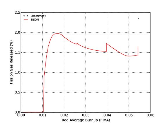
Figure 5: Fission gas release comparisons for Rodlet-2
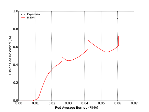
Figure 6: Fission gas release comparisons for Rodlet-4
Rod Internal Pressure
The only rod internal pressure data available for this experiment is from PIE puncture tests at the end-of-life. Figure 7 and Figure 8 show BISON's comparisons with the experimental data for Rodlet-2 and Rodlet-4, respectively. Both figures show BISON over predicts the rod internal pressure at the end of life.
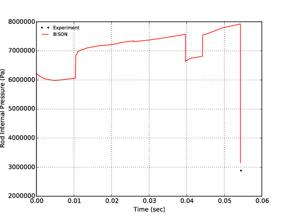
Figure 7: Rod internal pressure comparisons for Rodlet-2
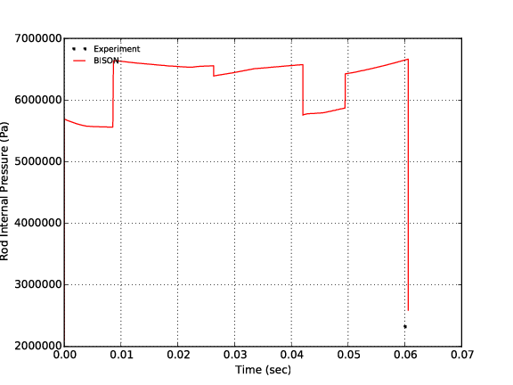
Figure 8: Rod internal pressure comparisons for Rodlet-4
Cladding Diametral Creep
The calculated final rod diameter as a function of axial position is compared to measured data. Figure 9 and Figure 10 show BISON's comparisons with the measured end-of-life rod average diameter data for Rodlet-2 and Rodlet-4, respectively. Both figures show BISON under predicts the cladding creep down which results in larger rod computed diameters than measured.
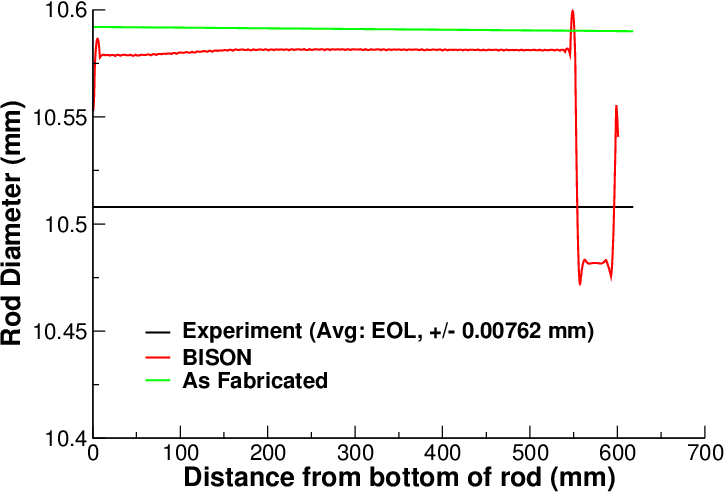
Figure 9: Rod diameter comparisons for Rodlet-2
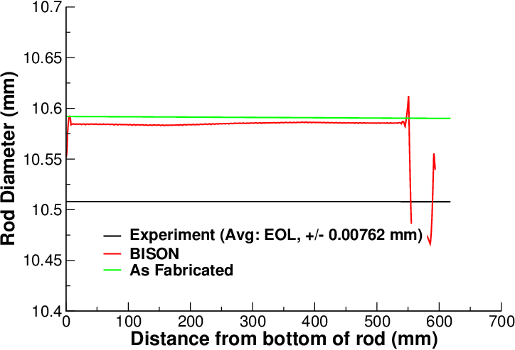
Figure 10: Rod diameter comparisons for Rodlet-4
Discussion
Based on the data presented above, several observations can be made regarding the results obtained from BISON analyses of Rodlets 2 and 4.
BISON predicts the EOL FGR reasonably well for both cases: From Figure 5 and Figure 6, sharp increases in FGR can be seen that correspond to large power drops. This rapid release of fission gas during power drop appears to be characteristic of the SIFGRs model implemented in BISON. This response may not be representative of FGR kinetics and warrants further review.
BISON over predicts the measured rod internal pressure for both cases by a fairly large margin.
BISON over predicts measured EOL cladding diameter except in the plenum region: Based on evaluation of these and other assessment cases, this behavior appears to be related to fuel swelling after fuel/cladding contact. Additionally, other effects on fuel deformation including relocation, densification, fuel creep, etc. could influence the behavioral response in these analyses.
Since cladding oxide thickness and hydrogen concentration data are available for Rodlet-2 and Rodlet-4, these characteristics should be evaluated in the future once these features are available in BISON.
References
- Siemens Power Corporation.
Annular-pellet barrier-clad fuel assemblies at the r. e. ginna pwr: hotcell examinations.
Technical Report EP 80-17 volume 1, Empire State Electric Energy Research Corporation, April 1997.[BibTeX]
- A. S. Giurgiuman and T. E. Wickersham.
Annular-pellet barrier-clad fuel r. e. ginna reactor lead fuel assemblies poolside examination.
Technical Report EP 80-17, Empire State Electric Energy Research Corporation, August 1994.
Final Report.[BibTeX]
- M. Limbäck and T. Andersson.
A model for analysis of the effect of final annealing on the in- and out-of-reactor creep behavior of zircaloy cladding.
In Zirconium in the Nuclear Industry: Eleventh International Symposium, ASTM STP 1295, 448–468. 1996.[BibTeX]
- OECDNEDB.
Ifpe/spc-re-ginna database.
Technical Report, OECD Nuclear Energy Data Bank, May 2002.[BibTeX]
- D. R. Packard.
Preirradiation characterization of ginna/eseerco lead fuel assemblies containing barrier cladding and annular pellets.
Technical Report XN-NF-85-79(P) Revision 1, Exxon Nuclear Company Inc., June 1986.[BibTeX]
- G. Pastore, L.P. Swiler, J.D. Hales, S.R. Novascone, D.M. Perez, B.W. Spencer, L. Luzzi, P. Van Uffelen, and R.L. Williamson.
Uncertainty and sensitivity analysis of fission gas behavior in engineering-scale fuel modeling.
Journal of Nuclear Materials, 465:398–408, 2015.[BibTeX]