IFA-534 Rods 18 and 19
Overview
The purpose of the IFA-534 experiment was to investigate the effect of fuel grain size on fission gas release and pellet-clad mechanical interaction (PCMI) in high burnup fuel. (Matsson, 1999). IFA-534 consisted of two rods (rod 18 and rod 19) which were base irriated in the Goesgen PWR to 52-55 MWd/Kg UO. These rods were then re-instrumented with internal pressure transducers and irradiated in the Halden Reactor. (IAEA, 2002-2007).
Test Description
The two test rods considered here were designed to test the effects of fuel grain size on fission gas release and PCMI. These two rods were instrumented with pressure transducers which provided on-line data as the experiment was irradiated in the Halden Reactor. The general rod specifications are summarized in which contains data taken from Reference (Matsson, 1999) and (IAEA, 2002-2007).
Table 1: IFA-534 Test Rod Specifications
| Fuel Rod | Measurement | Unit |
|---|---|---|
| Overall length | 0.533 | m |
| Fuel stack height | 0.411 | m |
| Nominal plenum height | 100 | mm |
| Number of pellets per rod | ||
| Rod 18 | 39 | mm |
| Rod 19 | 39 | mm |
| Fill gas composition | He | |
| Fill gas pressure | 2.15 | MPa |
| Fuel | Measurement | Unit |
| Material | UO | |
| Enrichment | ||
| Rod 18 | 3.84 | |
| Rod 19 | 3.79 | |
| Density | 95 | |
| Outer diameter | 9.12 | mm |
| Pellet geometry | flat end | |
| Grain diameter | ||
| Rod 18 | 22.1 | m |
| Rod 19 | 8.5 | m |
| Cladding | Measurement | Unit |
| Material | Zr-4 | |
| Outer diameter | 10.75 | mm |
| Inner diameter | 9.29 | mm |
| Wall thickness | 0.73 | mm |
Operating Conditions and Irradiation History
Rods 18 and 19 were base irradiated at the Goesgen PWR at a coolant pressure of 15.5 MPa and coolant inlet temperature of 308 C to approximatly 52 MWd/KgUO. The ramp testing was done in the Halden reactor and was operated with a coolant pressure of 3.2 MPa and an inlet temperature of 232 C. The Halden power history was provided by experimentalists from Halden (Wiesenack, 2014).
Model Description
Geometry and Mesh
Both fuels rods were meshed using 2-D axisymmetric quadratic elements. For simplicity, the pellet stack was modeled as a single continuous fuel column. The rods were identical so the same mesh was used for both. The fuel pellets had 111 axial elements and 11 radial elements, and the cladding consisted of 117 axial elements and 4 radial elements.
Material and Behavioral Models
The following material and behavioral models were used for the fuel:
UO2Thermal - NFIR: For temperature and burnup dependent thermal properties.
ComputeFiniteStrainElasticStress and UO2ElasticityTensor: elastic mechanical behavior
UO2VolumetricSwellingEigenstrain: volumetric expansion due to solid and gaseous swelling
UO2RelocationEigenstrain: relocation strains, relocation activation threshold power set to 5 kW/m
ComputeThermalExpansionEigenstrain:thermal expansion with a constant instanteous thermal expansion coefficient
UO2Sifgrs: fission gas release model used with the gaseous swelling model
UO2VolumetricSwellingEigenstrain
For the clad material, a constant thermal conductivity of 16 W/m-K was used and both thermal (primary and secondary) and irradiation creep were considered using the Limback creep model (Limbäck and Andersson, 1996). The following material and thermal behavior models were used for the cladding:
HeatConductionMaterial: Thermophysical material properties
ZryCreepLimbackHoppeUpdate and ZryElasticityTensor: mechanical creep and elastic deformation behavior for Zircaloy-2
ZryIrradiationGrowthEigenstrain: ESCORE model for volumetric swelling due to irradiation exposure
ZryThermalExpansionMATPROEigenstrain: thermal expansion of Zircaloy with the MATPRO model
Details and references for all of these models listed above can be found on the linked BISON documentation pages.
Input files
The BISON input and all supporting files (power histories, axial power profile) are provided with the code distribution at BISON/assessment/LWR/validation/IFA_534/analysis.
To avoid code duplication, the input files are built as follows: A base input file contains characteristics common to the entire assessment case and rod-specifc input files contain information/features unique to each rod. The base input file requires information contained in the rod-specific input files and cannot run on its own. Instead, the rod-specific files use the !include function to include the base input file information and create a complete input file that can be run.
Results Comparison
The purpose of the IFA-534 rod 18 and rod 19 experiments were to investigate the effect of fuel grain size on fission gas release. For this purpose the only parameter that was different in the build for these two rods was the fuel grain size. There is a slight difference in the enrichment of the two rods. This difference was accounted for by making a small modification to the individual rod power based on the acutal fuel weight to get 52 MWd/Kg UO at the beginning of the Halden run. (Halden, 2003) Fission gas relase is compared against the experiment numbers and other well known fuel performance codes. Pressure data for both rods was collected with an in-situ pressure transducer. Pressure is compared between BISON and the Halden data. The data for these comparisons was digitized from plots in the FUMEX-II Final Report (IAEA, 2002-2007)
IFA-534, Rod 18
Fission Gas Release
The BISON end result for fission gas release compared very well the the data that Halden collected. As one may note the BISON run does not start at zero like the Halden does. After the base irradiation the rod was refabricated so that the pressure transducer could be added. At this time the rod was also refilled with pure He gas. BISON currently misses rebasing the fission gas that was released prior to refabracation. We are currently discussing the best course of action to model this.
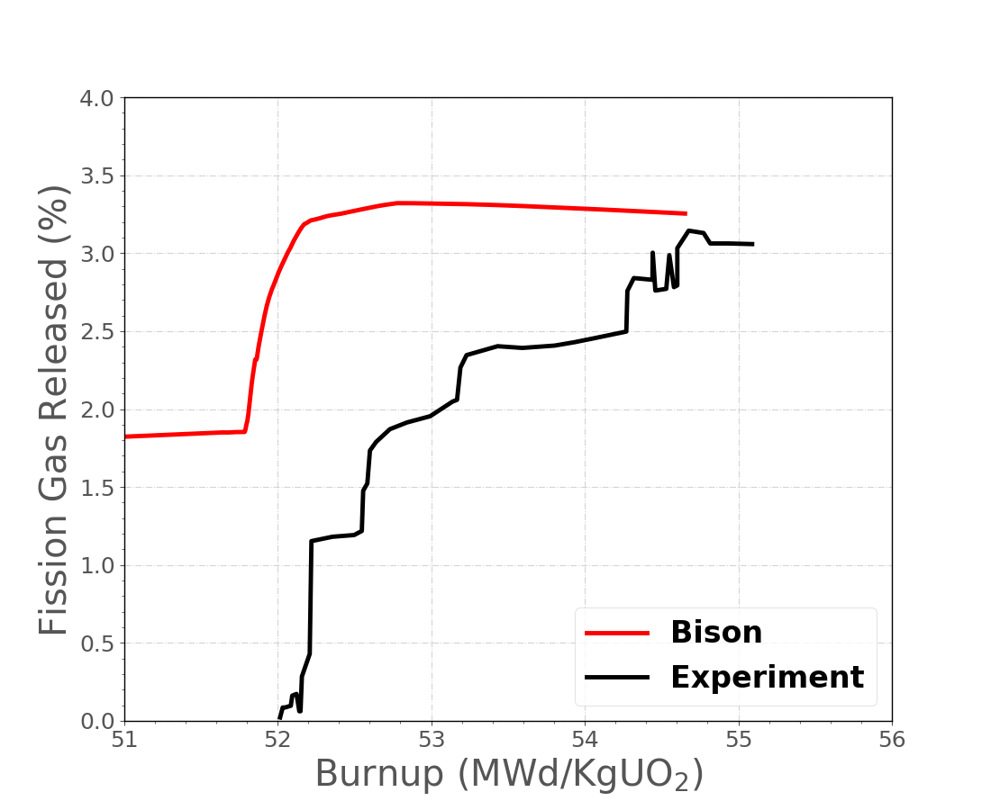
Figure 1: Comparison of measured and BISON predicted fission gas release during Halden irradiation for rod 18.
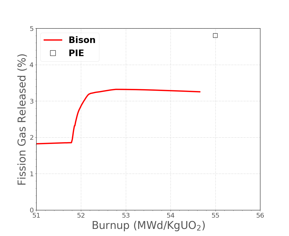
Figure 2: Comparison of the post irradiation examination and the BISON predicted fission gas release for rod 18.
Pressure
As stated previously the rod had an in-situ pressure transmitter installed at refabraction. Due to this we have real online data of the experiment's pressure. The BISON result for the pressure is off by a bit in the start and then compares very well in the end. One possible reason for the higher pressure at the start is the extra fission gas present in the model mentioned in the discussion above. Another problem that was encountered with pressure was the model predicted gas volume. The gas volume at the start of the BISON run (base irradiation) was correct, according to the FUMEX data. At refabracation the model underestimate gas volume leading to a much higher plenum pressure. As a temporary work around the mesh was adjusted such that the gas volume was high in the base irradiation and then was calculated by BISON to be correct in the Halden run. In this case the Fumex reported gas volume for the base irradiation and Halden run is 5.1 cm. A gas volume of 6.1 cm was used for the BISON base irradiaion to achieve approximately 5.1 cm for the Halden run.
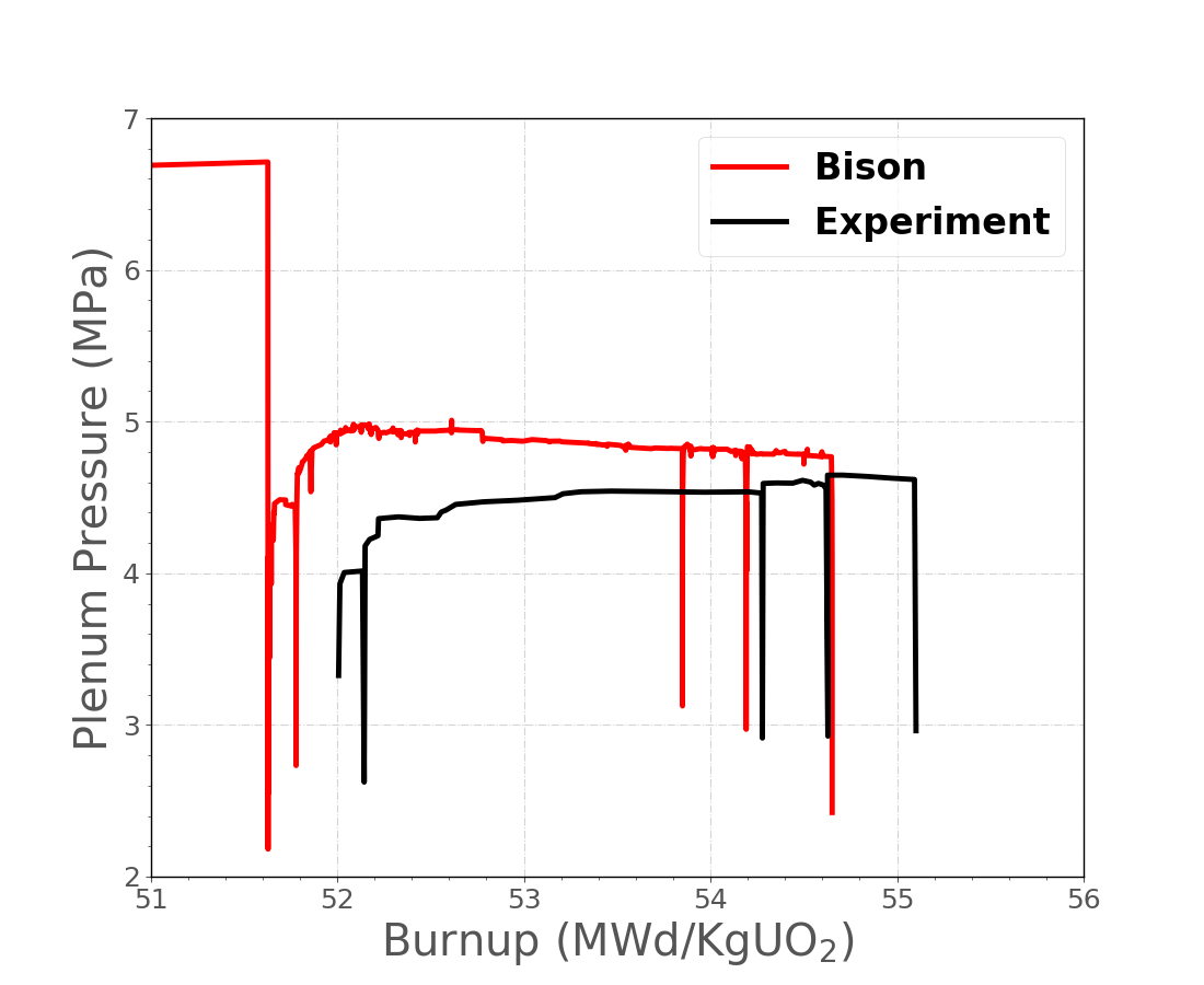
Figure 3: Comparison of measured and BISON predicted plenum pressure for rod 18.
IFA-534, Rod 19
Fission Gas Release
As with the the previous rod, 18, rod 19 compares well to the Halden data for fission gas release. Rod 19 does have the same issue as rod 18 in that fission gas does not start at zero. There is an added issue with the rod 19 data, there is a slight shift in the x-axis, burnup. This is common as burnup gets calculated in different manners with slightly different numbers and the shift is acceptable.
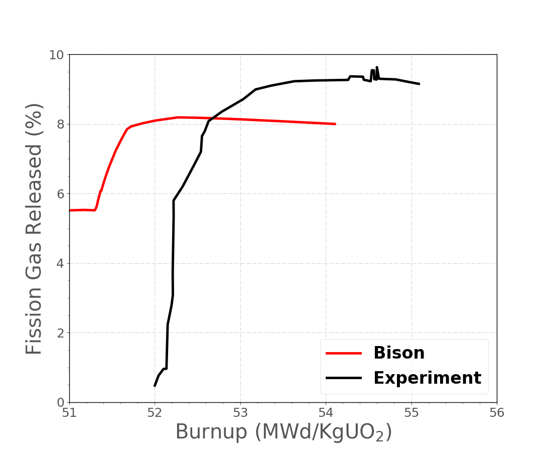
Figure 4: Comparison of measured and BISON predicted fission gas release during Halden irradiation for rod 19.
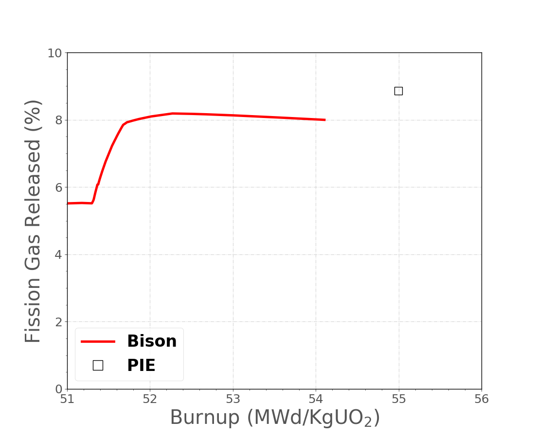
Figure 5: Comparison of the post irradiation examination and the BISON predicted fission gas release for rod 19.
Pressure
The pressure comparision is acceptable between BISON and the experiment. Once again, rod 19 has the same issues as rod 18 so the same methods where employed. These work arounds may account for the difference in the pressure. A gas volume of 6.1 cm was used for the BISON base irradiaion to achieve approximately 5.1 cm for the Halden run.
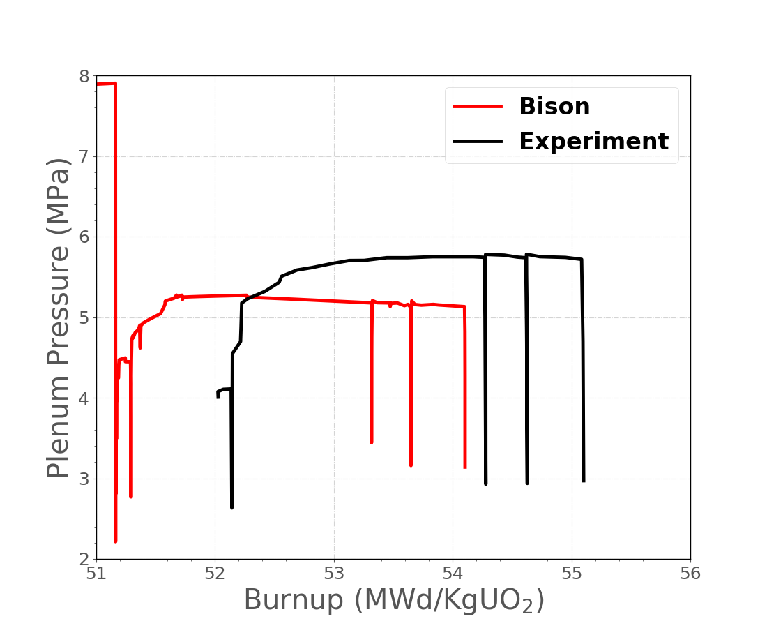
Figure 6: Comparison of measured and BISON predicted plenum pressure for rod 19.
Discussion
In modeling these two rods it came to the surface that how refabracation is modeled needs to be looked at more closely. This is a good thing as it will lead to a better overall BISON. Topics such as what to do with the released fission gas at refab and the BISON calculated gas volume are being worked out. As for how refabracation works currently a user enters plenum volume, gas temperature, gas content and gas pressure. BISON uses these to calulate the number of moles of gas in the plenum. BISON then looks to the postprocessors for the previous time step to calculate the gas volume that it is going to use for the continuation of the run. This was done to attempt to capture the fuel swelling and other physics that happened in the base irradiation. As stated better approaches are being looked in to.
References
- Halden.
QA Report for Halden IFA-534.14.
May 2003.
Revision 1.[BibTeX]
- IAEA.
Fuel Modelling at Extened Burnup (FUMEX-II): Report of a Coordinated Research Project 2002-2007.
Technical Report IAEA-TECDOC-1687, International Atomic Energy Agency, 2002-2007.[BibTeX]
- M. Limbäck and T. Andersson.
A model for analysis of the effect of final annealing on the in- and out-of-reactor creep behavior of zircaloy cladding.
In Zirconium in the Nuclear Industry: Eleventh International Symposium, ASTM STP 1295, 448–468. 1996.[BibTeX]
- I. Matsson.
The Effects of Grain Size on FGR and PCMI in High Burnup Fuel (IFA-534.14).
Technical Report HWR-558, Halden, February 1999.[BibTeX]
- Wolfgang Wiesenack.
April 2014.
IFA-534 Rods 18 and 19 Halden data.[BibTeX]