IFA 515.10 Rod A1
Overview
The IFA-515.10 Rod A1 experiment was irradiated in the Halden Boiling Water Reactor (HBWR) for approximately 6 years to a discharge burnup of 76 MWd/kg UO. Rod A1 was fitted with a fuel centerline expansion thermometer (ET) to measure the fuel centerline temperature during irradiation (T. Tverberg, M. Amaya, 2001).
Test Description
Rod Design Specifications
Rod A1 in the IFA-515.10 series was an annular short rod (0.2455 m overall length) enriched to 11.5%. The fuel and cladding specifications are tabulated in Table 1.
Table 1: IFA-515.10 rod A1 Test Rod Specifications
| Fuel Rod | Measurement | Unit |
|---|---|---|
| Overall length | 0.2455 | m |
| Fuel stack height | 0.212 | m |
| Nominal plenum height | 19.0 | mm |
| Fill gas composition | He | |
| Fill gas pressure | 1.0 | MPa |
| Fuel | Measurement | Unit |
| Material | UO | |
| Enrichment | 11.5 | |
| Density | 96.8 | |
| Inner diameter | 1.80 | mm |
| Outer diameter | 5.56 | mm |
| Pellet geometry | flat end | |
| Average grain diameter | 15.5 | m |
| Average fuel roughness | 0.28 | m |
| Insulator Pellet | Measurement | Unit |
| Material | Al O | |
| Inner diameter | 1.80 | mm |
| Outer diameter | 5.56 | mm |
| Pellet length | 5.0 | mm |
| Cladding | Measurement | Unit |
| Material | Zr-2 | |
| Outer diameter | 6.53 | mm |
| Inner diameter | 5.61 | mm |
| Zr-Barrier thickness | 0.05 | mm |
| Wall thickness | 0.46 | mm |
Operating Conditions and Irradiation History
The HBWR operating conditions are tabulated in Table 2. The reactor power history is shown in Figure 1. The measured reactor coolant temperature was used as the boundary temperature on the cladding outer surface.
Table 2: HBWR operating conditions
| Parameter | Value | Unit |
|---|---|---|
| Average coolant temperature | 195 | C |
| Coolant pressure | 3.4 | MPa |
| Fast neutron flux | 1.6 | n/(cms) per (kW/m) |
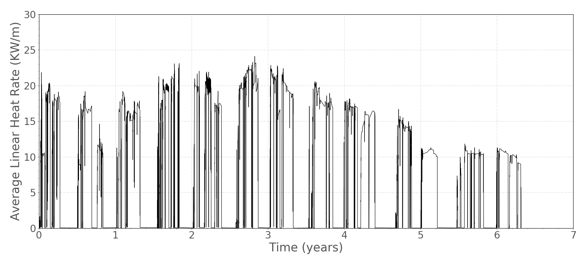
Figure 1: Halden irradiation through life power profile for IFA-515.10 rod A1.
Model Description
Geometry and Mesh
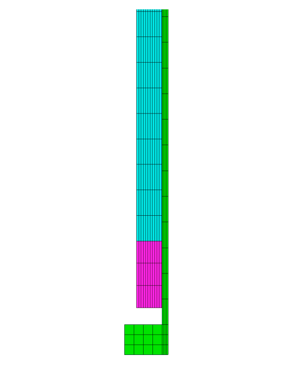
Figure 2: 2-D axisymmetric quadratic mesh for IFA-515.10 Rod A1 simulation. Note: This is only a cut from the bottom of the fuel rod meant to show the fuel and insulator pellet. The volume where the expansion thermometer would be in the experiment can also be seen.
The assumed geometry and mesh are shown in Figure 2. The fuel pellet stack was modeled as a smeared column with merged insulator pellets. The insulator pellets were modeled as UO (ie. the same mechanical and thermal properties) to make the simulation easier to run. The expansion thermometer was modeled as a void in the pellet/insulator stack, this was also done to ease the simulation. The BISON fuel centerline temperature was calculated as an average of the pellet interior (BISON sideset 13). The plenum length for the mesh was adjusted from the experiment length to account for the difference in volume caused by the voided expansion thermometer. The initial gas volume in the simulation was 2.3 cc, as listed in (T. Tverberg, M. Amaya, 2001).
A 2-dimensional axisymmetric quadratic mesh was used. The fuel column was meshed with 111 axial and 11 radial elements (aspect ratio 11.2) and the insulator pellets with 3 axial and 11 radial elements (aspect ratio 9.75). The cladding was meshed with 150 axial and 4 radial elements (aspect ratio 16.7).
Material and Behavioral Models
The following material and behavioral models were used for the fuel:
UO2Thermal - NFIR: For temperature and burnup dependent thermal properties.
ComputeFiniteStrainElasticStress and UO2ElasticityTensor: elastic mechanical behavior
UO2VolumetricSwellingEigenstrain: volumetric expansion due to solid and gaseous swelling
UO2RelocationEigenstrain: relocation strains, relocation activation threshold power set to 5 kW/m
ComputeThermalExpansionEigenstrain:thermal expansion with a constant instanteous thermal expansion coefficient
UO2Sifgrs: fission gas release model used with the gaseous swelling model
UO2VolumetricSwellingEigenstrain
For the clad material, a constant thermal conductivity of 16 W/m-K was used and both thermal (primary and secondary) and irradiation creep were considered using the Limback creep model (Limbäck and Andersson, 1996). The following material and thermal behavior models were used for the cladding:
HeatConductionMaterial: Thermophysical material properties
ZryCreepLimbackHoppeUpdate and ZryElasticityTensor: mechanical creep and elastic deformation behavior for Zircaloy-2
ZryIrradiationGrowthEigenstrain: ESCORE model for volumetric swelling due to irradiation exposure
ZryThermalExpansionMATPROEigenstrain: thermal expansion of Zircaloy with the MATPRO model
Details and references for all of these models listed above can be found on the linked BISON documentation pages.
Input files
The BISON input and all supporting files (power histories, axial power profile, cladding surface temperature boundary condition, fast neutron flux history, etc.) for this case are provided with the code distribution at bison/assessment/LWR/validation/IFA_515_RodA1/analysis.
Simulation Parameters and Assumptions
As mentioned in the Geometry & Mesh section, the mesh used is not an exact representation of the experiment. To make the simulation run easier the insulator pellets were modeled as UO instead of AlO. Merged materials of the same type in the mesh make for easier mechanics (ie. thermal expansion and swelling). The insulator pellets were not included in the heat source term. The expansion thermometer was neglected in this mesh. This was done to alleviate troubles with thermal and mechanical properties between the thermometer and the fuel/insulator stack. The plenum length of the fuel rod was adjusted to account for the extra gas volume made from the voided thermometer. The initial gas volume is 2.3 cc as listed in (T. Tverberg, M. Amaya, 2001). The zirconium barrier on the cladding interior was not modeled, but the cladding thickness was modeled as specified in (T. Tverberg, M. Amaya, 2001). The initial fuel grain size and the fuel roughness were inputted into BISON as averages of the numbers that were given in (T. Tverberg, M. Amaya, 2001). The test was short and located in a region were the axial flux variation average to peak is small, less than 1.03 (T. Tverberg, M. Amaya, 2001). Due to this peaking factors for power and temperature were not input into BISON.
Results Comparison
A BISON postprocessor was used to extract the centerline temperature as an average of the interface of the pellet interior surface and the ET (BISON sideset 13). This provides an accurate representation of the average fuel centerline temperature since, in this case, no axial variation in fuel temperature.
Temperature
The BISON results for the fuel centerline temperature show that BISON approximates the actual experimental values well. A plot of the comparison can be seen below in Figure 3. There are some noticeable differences between BISON and the experiment on the peaks at the beginning of the experiment. The difference between the BISON results and the experiment becomes less as the simulation progresses. This points to possible issues in the gap heat transfer model. As fuel centerline temperature was the only parameter that was measured we can only speculate on the other effects that may have contributed to this difference. Figure 4 shows a comparison of fuel centerline temperature and linear heat rate. This plot shows that BISON does tend to under predict through the simulation at all powers. It should be noted that the experiment low outliers are from instrument issues and should be ignored. Figure 5 is the same data as Figure 4, but the results are compartmentalized by burnup level to investigate BISON performance throughout the simulation more closely. Burnup [0-20) shows that BISON does under predict during the early stages of the simulation. This is before the gap closes, which supports the previous hypothesis. As the simulation progresses the burnup groups [0-20), [20,40), [40,60), and [60,80) show that the comparison of BISON results to experiment data improves.
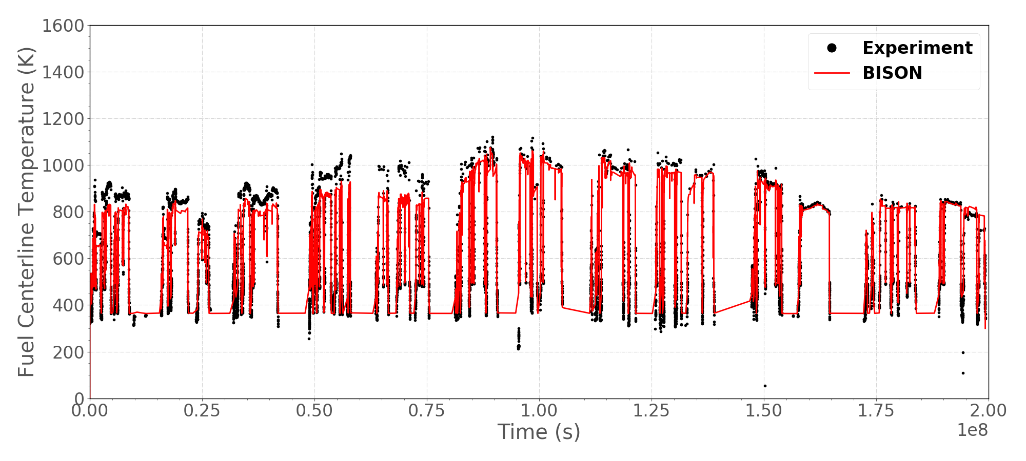
Figure 3: A comparison of fuel centerline temperatures from BISON calculations and experimental measurements.
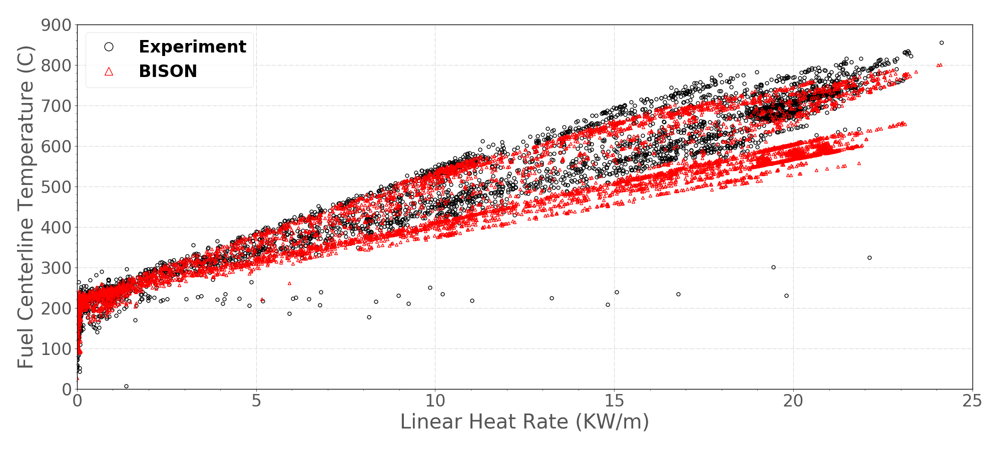
Figure 4: A comparison of measured and BISON predicted average fuel centerline temperature as a function of power.
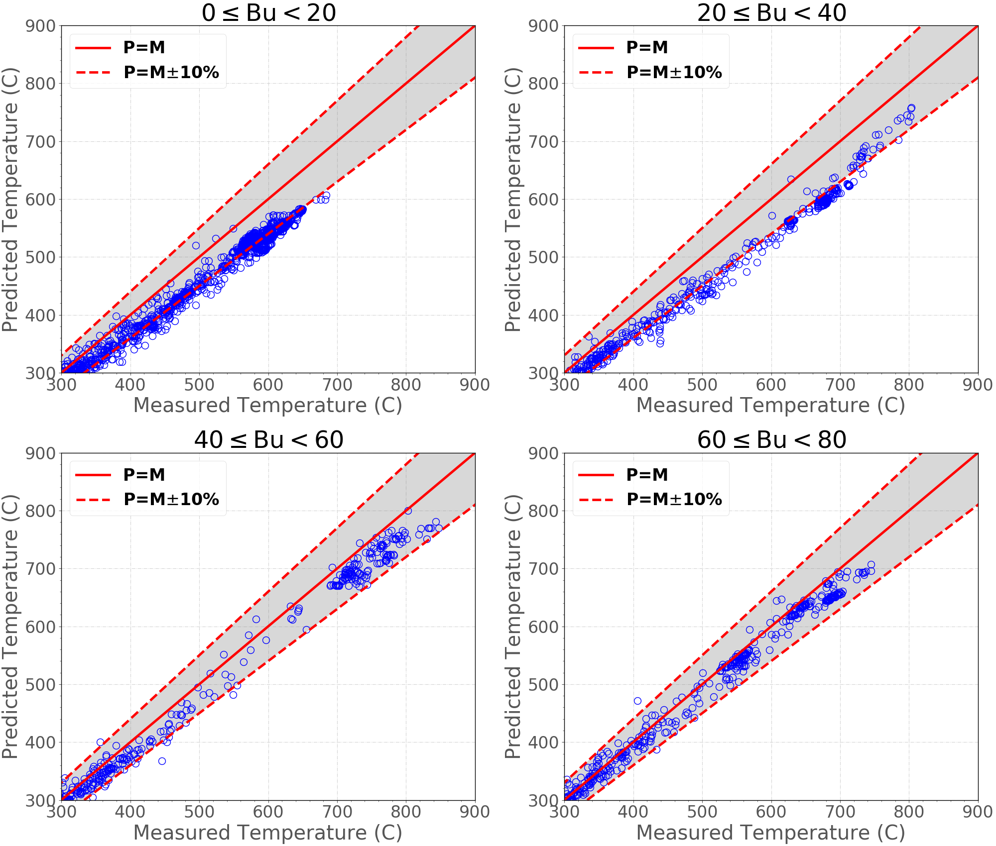
Figure 5: Measured fuel centerline temperatures against the predictions for IFA 515.10 Rod A1 at four different burnup ranges ( for measured; for predicted).
Differences between the measurements and the predictions are quantified in terms of the validation metrics. The results are tabulated in Table 3.
Table 3: The validation metrics for the fuel centerline temperature predictions.
| Bu(MWd/kgUO) | (-) | II (K) | RMSE (K) | rRMSE (%) |
|---|---|---|---|---|
| 0Bu20 | 0.936 | 83.8 | 38.7 | 5.7 |
| 20Bu40 | 0.939 | 90.1 | 37.6 | 6.1 |
| 40Bu60 | 0.962 | 98.1 | 33.3 | 8.3 |
| 60Bu80 | 0.977 | 69.1 | 24.4 | 5.6 |
Discussion
The results show that the fuel centerline temperature compares well between the BISON predicted and experiment measurements. Although this is true the results also show that there are possible weaknesses in the gap conductance in the early stages of the simulation. Results and information from this simulation will help to guide future BISON developments.
References
- M. Limbäck and T. Andersson.
A model for analysis of the effect of final annealing on the in- and out-of-reactor creep behavior of zircaloy cladding.
In Zirconium in the Nuclear Industry: Eleventh International Symposium, ASTM STP 1295, 448–468. 1996.[BibTeX]
- T. Tverberg, M. Amaya.
Study of thermal behavious of UO$_2$ and (U,Gd)O$_2$ to high burnup (IFA-515).
Technical Report HWR-671, Halden, February 2001.[BibTeX]