IFA-432 Rods 1, 2, and 3
Overview
The IFA-432 experiment was part of an effort by the US NRC to obtain well-characterized experimental data under conditions that simulate long-term steady LWR operation (Bradley et al., 1982). IFA-432 was a heavily instrumented fuel assembly irradiated in the Halden boiling water reactor from 1975 to 1984. The test rods initially contained fresh fuel and were operated at power levels near the upper bound for full-length commercial fuel rods.
The IFA-432 assembly included six instrumented rods, each with centerline temperature instrumentation in both the top and bottom ends of the fuel column. Three of the six rods (Rods 1, 2, 3) are the focus of this assessment. Rod 1 achieved a burnup of approximately 30 MWd/KgU, while rods 2 and 3 achieved burnups of approximately 45 MWd/kgU. Two of the temperature measurements failed prematurely. Rod 2 contained an ultrasonic thermometer at the top of the rod, which failed very early and no data were collected. The Rod 1 upper thermocouple failed after 150 days.
The IFA-432 assembly also contained neutron detectors, coolant thermocouples, a coolant flow meter, and a transducer to measure internal rod pressure.
Test Description
The three test rods considered here were designed to simulate BWR-6 rod cladding material and dimensions, and included only differences in fuel-cladding gap size. The general rod specifications are summarized in which contains data taken from Reference (C. R. Hann, D. D. Lanning, E. R. Bradley, R. K. Marshall, M. E. Cunningham, and R. E. Williford, 1978).
Table 1: IFA-432 Test Rod Specifications
| Fuel Rod | Measurement | Unit |
|---|---|---|
| Overall length | 0.635 | m |
| Fuel stack height | 0.5791 | m |
| Nominal plenum height | 25.4 | mm |
| Number of pellets per rod | ||
| Rod 1 | 45 | mm |
| Rod 2 | 44 | mm |
| Rod 3 | 44 | mm |
| Fill gas composition | He | |
| Fill gas pressure | 0.1 | MPa |
| Fuel | Measurement | Unit |
| Material | UO | |
| Enrichment | 10 | |
| Density | 95 | |
| Inner diameter | 1.752 | mm |
| Outer diameter | ||
| Rod 1 | 10.681 | mm |
| Rod 2 | 10.528 | mm |
| Rod 3 | 10.833 | mm |
| Pellet geometry | flat end | |
| Grain diameter | 22-77 | m |
| Cladding | Measurement | Unit |
| Material | Zr-2 | |
| Outer diameter | 12.789 | mm |
| Inner diameter | 10.909 | mm |
| Wall thickness | 0.94 | mm |
The fuel rod length was significantly shorter than full-length commercial rods to fit within the short length of the Halden reactor core. Slight differences in the pellet diameters, as defined in Table 1, resulted in a variation in the initial radial fuel-clad gaps of 115 m (Rod 1), 190 m (Rod 2), and 38 m (Rod 3).
Operating Conditions and Irradiation History
The reactor was operated with a coolant pressure of 3.4 MPa and an inlet temperature of 510 K. The power history was provided by experimentalists from Halden (Wiesenack, 2012).
Model Description
Geometry and Mesh
All three fuels rods were meshed using 2-D axisymmetric quadratic elements. For simplicity, the pellet stack was modeled as a single continuous fuel column. The thermocouple holes were modeled as closely to the experiment as possible at the top and bottom of the fuel rod. Figure 1 shows a scaled view of the mesh for rod 1. Rods 2 and 3 were identical with exceptions to the thermocouple hole length and the gap width.
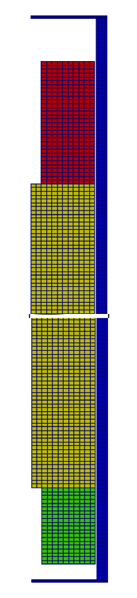
Figure 1: Scaled view of the finite element mesh for rod 1 (aspect ratio scaled 10x).
Material and Behavioral Models
The following material and behavioral models were used for the fuel:
UO2Thermal - NFIR: temperature and burnup dependent thermal properties
ComputeFiniteStrainElasticStress and UO2ElasticityTensor: elastic mechanical behavior
UO2RelocationEigenstrain: relocation strains, relocation activation threshold power set to 5 kW/m
ComputeThermalExpansionEigenstrain: thermal expansion with a constant instanteous thermal expansion coefficient
UO2VolumetricSwellingEigenstrain : volumetric expansion due to solid and gaseous swelling
UO2Sifgrs: fission gas release model used with the gaseous swelling model
UO2VolumetricSwellingEigenstrain(Pastore et al., 2015)
For the clad material, a constant thermal conductivity of 16 W/m-K was used and both thermal and irradiation creep were considered using the Limback model (Limbäck and Andersson, 1996). The fast neutron flux used in the irradiation creep model was 1.6e12 n/m-s per W/m (Killeen et al., 2007). This value was multiplied by the power history (W/m) and the axial peaking factors to approximate the fast neutron flux. The following material and thermal behavior models were used for the cladding:
HeatConductionMaterial: Thermophysical material properties
ZryCreepLimbackHoppeUpdate and ZryElasticityTensor: mechanical creep and elastic deformation behavior for Zircaloy-4
ZryIrradiationGrowthEigenstrain: ESCORE model for volumetric swelling due to irradiation exposure
ZryThermalExpansionMATPROEigenstrain: thermal expansion of Zircaloy with the MATPRO model
Boundary and Operating Conditions
The clad outer wall temperature was assumed constant at 513.3 K. The input BOL power histories for Rods 1 and 3 are shown in Figure 2.
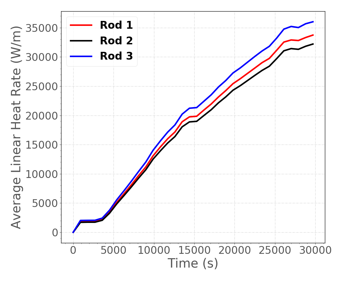
Figure 2: Input BOL power history
Input files
The BISON input and all supporting files (power histories, axial power profile) are provided with the code distribution at bison/assessment/LWR/validation/IFA_432/analysis.
To avoid code duplication, the input files are built as follows: A base input file contains characteristics common to the entire assessment case and rod-specifc input files contain information/features unique to each rod. The base input file requires information contained in the rod-specific input files and cannot run on its own. To combine the base input file with the parameter file, simply list the different files when running the simulation. For example, for rod 3, call IFA_432_rod3.params ../IFA_432_Base.i.
Results Comparison
BISON postprocessors were used to record the power and temperature histories at nodes corresponding to the upper and lower thermocouple positions.
Centerline Temperature at Beginning of Life
Initial comparisons were made to centerline fuel temperature measurements during the first rise to power, or the period referred to as the Beginning of Life (BOL). Comparisons during this period are important since they isolate several important aspects of fuel rod behavior before complexities associated with higher burnups are encountered. For example, good prediction of BOL centerline temperature requires accurate models for the unirradiated fuel thermal conductivity, gap gas conductivity, thermal expansion of both the fuel and clad materials (which set the gap width), clad conductivity, and fuel relocation.
Figure 3, Figure 4, and Figure 5 show centerline temperature comparisons at BOL for Rods 1, 2, and 3, respectively. Note that for Rod 2, only lower thermocouple comparisons are possible since a gamma thermometer that failed to operate occupied this position in the rod (C. R. Hann, D. D. Lanning, E. R. Bradley, R. K. Marshall, M. E. Cunningham, and R. E. Williford, 1978).
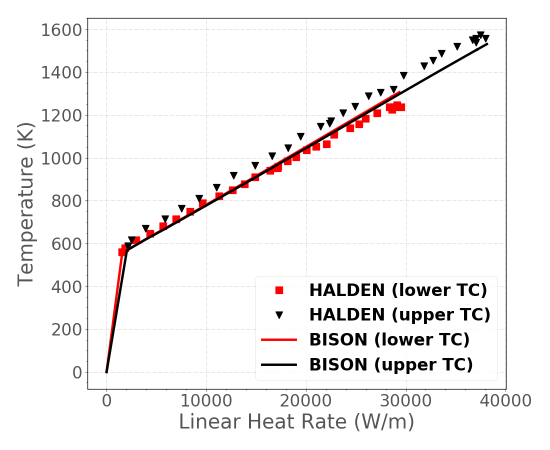
Figure 3: Measured vs. BISON predicted fuel centerline temperatures at BOL for Rod 1.
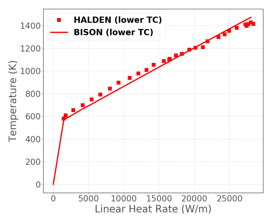
Figure 4: Measured vs. BISON predicted fuel centerline temperatures at BOL for Rod 2.
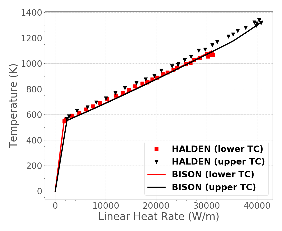
Figure 5: Measured vs. BISON predicted fuel centerline temperatures at BOL for Rod 3.
Differences between the measurements and the predictions are quantified in terms of the validation metrics. The results are tabulated in Table 2. Comparisons for all three rods are in good agreement.
Table 2: The validation metrics for the fuel centerline temperature predictions.
| Experiment | (-) | II (K) | RMSE (K) | rRMSE (%) |
|---|---|---|---|---|
| Rod 1 (lower TC) | 0.984 | 68.2 | 30.0 | 2.7 |
| Rod 1 (upper TC) | 0.965 | 77.1 | 57.2 | 5.2 |
| Rod 2 (lower TC) | 0.985 | 59.0 | 35.9 | 3.7 |
| Rod 3 (lower TC) | 0.992 | 28.7 | 16.2 | 2.1 |
| Rod 3 (upper TC) | 0.971 | 61.6 | 41.1 | 4.3 |
Discussion
The recommended activation energy for the ESCORE relocation model implemented in BISON is 19.7 kW/m (Rashid et al., 2004). Based on experimental evidence of fuel cracking as a function of rod power, Wolfgang Wiesenack from Halden recommended lowering this activation threshold power to 5 kW/m. This lower value was further confirmed through a recent relocation calibration study (Swiler et al., 2013) and is now used as the default value in BISON.
References
- E. R. Bradley, M. E. Cunningham, and D. D. Lanning.
Final data report for the instrumented fuel assembly (IFA)-432.
Technical Report NUREG/CR-2567, PNNL-4240, Pacific Northwest National Laboratory, 1982.[BibTeX]
- J. C. Killeen, J. A. Turnbull, and E. Sartori.
Fuel modelling at extended burnup: IAEA coordinated research project FUMEX-II.
In Proceedings of the 2007 International LWR Fuel Performance Meeting. San Francisco, California, Paper 1102, September 30-October 3 2007.[BibTeX]
- M. Limbäck and T. Andersson.
A model for analysis of the effect of final annealing on the in- and out-of-reactor creep behavior of zircaloy cladding.
In Zirconium in the Nuclear Industry: Eleventh International Symposium, ASTM STP 1295, 448–468. 1996.[BibTeX]
- G. Pastore, L.P. Swiler, J.D. Hales, S.R. Novascone, D.M. Perez, B.W. Spencer, L. Luzzi, P. Van Uffelen, and R.L. Williamson.
Uncertainty and sensitivity analysis of fission gas behavior in engineering-scale fuel modeling.
Journal of Nuclear Materials, 465:398–408, 2015.[BibTeX]
- Y Rashid, R Dunham, and R Montgomery.
Fuel Analysis and Licensing Code: FALCON MOD01.
Technical Report, Electric Power Research Institute, December 2004.[BibTeX]
- L. P. Swiler, R. L. Williamson, and D. M. Perez.
Calibration of a fuel relocation model in BISON.
In Proceedings of the International Conference on Mathematics and Computational Methods Applied to Nuclear Science and Engineering. Sun Valley, Idaho, May 5-9, 2013.[BibTeX]
- Wolfgang Wiesenack.
November 2012.
IFA-432 Rods 1, 2, and 3 Halden data.[BibTeX]
- C. R. Hann, D. D. Lanning, E. R. Bradley, R. K. Marshall, M. E. Cunningham, and R. E. Williford.
Data Report for the NRC/PNL Halden Assembly IFA-432.
Technical Report NUREG/CR-0560, PNL-2673, Pacific Northwest National Laboratory, 1978.[BibTeX]