REGATE
Overview
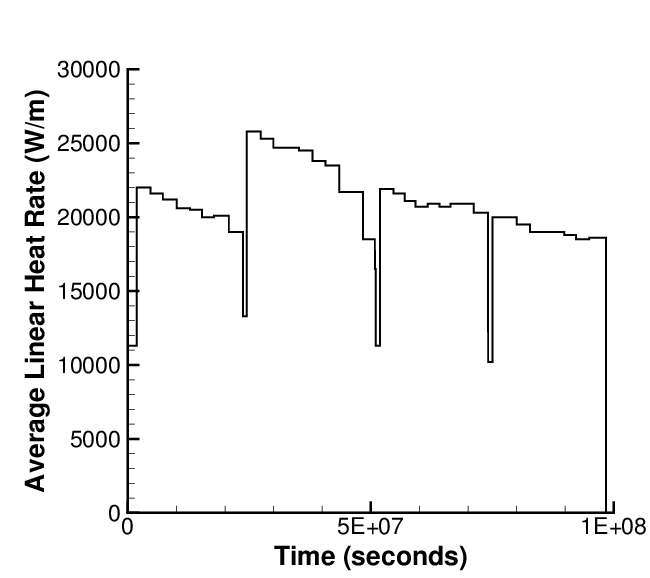
Figure 1: Rod average power history in the Gravlines 5 reactor.
Regate is one of the experiments of the Fuel Modeling at Extended Burnup (FUMEX-II) program (IAEA, 2002-2007). This experiment was carried out in order to provide data on Fission Gas Release (FGR) and clad diameter change. The rod is a short fuel segment irradiated in a commercial PWR and ramped in the french SILOE test reactor. The original segment was base irradiated in the Gravlines 5 PWR up to 47.415 MWd/kgHM.
Non-destructive post-irradiation examination (PIE) was performed on the fuel segment after discharge from the Gravlines 5 PWR with measurements on clad diameter and total fission gas release (based on Kr-85 gamma scan measurements), the total measured FGR after base irradiation was 1.5%. It is important to note that the fuel segment was not subject to any re-fabrication after base irradiation in Gravlines 5 PWR (power history shown in Figure 1).
The Kr-85 concentration was also measured with gamma scanning to measure a total of 9.3% FGR after the ramp test in the SILOE reactor. Puncturing tests were done after the power ramp in the SILOE reactor, to measure the total FGR of 10.2%. The oxide layer thickness and total clad diameter were also measured in PIE after the ramp test.
BISON comparisons to clad diameter and FGR are reported herein.
Test Description
Rod Design Specifications
The geometric input parameters for the FumexII-Regate case are summarized in Table 1.
Table 1: Regate geometric input parameters
| Fuel Rod | ||
|---|---|---|
| Overall length | 0.522 | m |
| Fuel stack height | 0.43595 | m |
| Nominal plenum height | 48.15 | mm |
| Number of pellets per rod | 32 | |
| Fill gas composition | He | |
| Fill gas pressure | 2.5 | MPa |
| Fuel | ||
| Material | UO | |
| Enrichment | 4.487 | |
| Density | 94.8 | |
| Outer diameter | 8.192 | mm |
| Pellet geometry | dished | |
| Grain diameter | 8.7 | m |
| Pellet Dishing | ||
| Dish diameter | 6 | mm |
| Dish depth | 0.32 | mm |
| Chamfer width | 0.531 | mm |
| Chamfer depth | 0.16 | mm |
| Cladding | ||
| Material | Zr-2 | |
| Outer diameter | 9.5 | mm |
| Inner diameter | 8.36 | mm |
| Wall thickness | 0.57 | mm |
Operating Conditions and Irradiation History
The irradiation was adjusted by varying the distance of the rig from the SILOE core. The ramp test irradiation history consisted of a pre-condition power step of 19.5 kW/m (peak power) for 48 hours, prior to ramping at 1.0 kW/m/min up to 38.5 kW/m (peak power) which was held for 1.5 hours. The rod average power history during the SILOE irradiation is shown in Figure 2. As the height of the SILOE reactor (0.6 m) is comparable to the segment length (0.44 m), the axial power is not flat during the ramp test, leading to values of of 0.9 and of 0.65.
Table 2: Operational input parameters.
| Base Irradiation | ||
|---|---|---|
| Clad temperature | C | 317 |
| Coolant pressure | MPa | 15.5 |
| Fast neutron flux | Figure 3 | |
| Power Ramps | ||
| Clad temperature | C | 77 -338 |
| Coolant pressure | MPa | 13 |
| Fast neutron flux | n/(cms) | 2.0 |
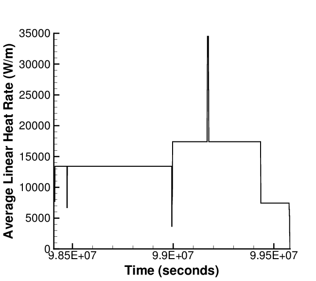
Figure 2: Rod average power history in the SILOE reactor.
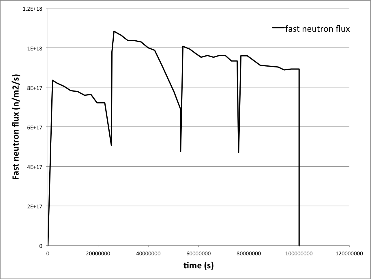
Figure 3: Fast neutron flux history. This history was supplied with the experimental data.
Model Description
Geometry and Mesh
A 2D-RZ axisymmetric discrete pellet mesh with quadratic elements was used to model this experiment. Each pellet was meshed with 16 axial and 9 radial elements. The clad was meshed with 4 axial elements. Figure 4 shows a section of the meshed with a temperature contour plot during the ramp test.
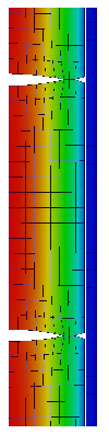
Figure 4: Section of mesh used for Regate simulation with temperature contour during the ramp test in the SILOE reactor.
Material and Behavioral Models
The following material and behavioral models were used for the fuel:
UO2Thermal - NFIR: For temperature and burnup dependent thermal properties.
ComputeFiniteStrainElasticStress and UO2ElasticityTensor: elastic mechanical behavior
UO2VolumetricSwellingEigenstrain: Volumetric expansion due to solid and gaseous swelling
UO2RelocationEigenstrain: Relocation strains, relocation activation threshold power set to 5 kW/m
ComputeThermalExpansionEigenstrain:Thermal expansion with a constant instantaneous thermal expansion coefficient
UO2Sifgrs: Fission gas release model used with the gaseous swelling model
UO2VolumetricSwellingEigenstrain
For the clad material, a constant thermal conductivity of 16 W/m-K was used and both thermal (primary and secondary) and irradiation creep were considered using the Limback creep model (Limbäck and Andersson, 1996). The following material and thermal behavior models were used for the cladding:
HeatConductionMaterial: Thermophysical material properties
ZryCreepLimbackHoppeUpdate and ZryElasticityTensor: mechanical creep and elastic deformation behavior for Zircaloy-2
ZryIrradiationGrowthEigenstrain: ESCORE model for volumetric swelling due to irradiation exposure
ZryThermalExpansionMATPROEigenstrain: Thermal expansion of Zircaloy with the MATPRO model
Details and references for all of these models listed above can be found on the linked BISON documentation pages. Due to the high misses stress in the clad, plasticity was also used to get the proper deformation during the power ramp in the RisøDR3 reactor.
Input files
The BISON input and all supporting files (power histories, axial power profile, fast neutron flux history, etc.) for this case are provided with the code distribution at bison/assessment/LWR/validation/FUMEXII_Regate/analysis.
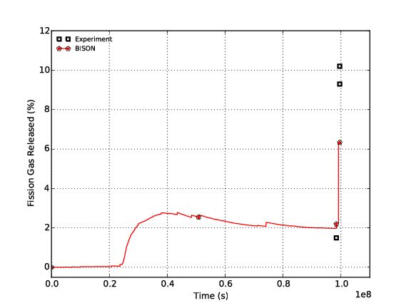
Figure 5: BISON FGR comparisons to experimental data.
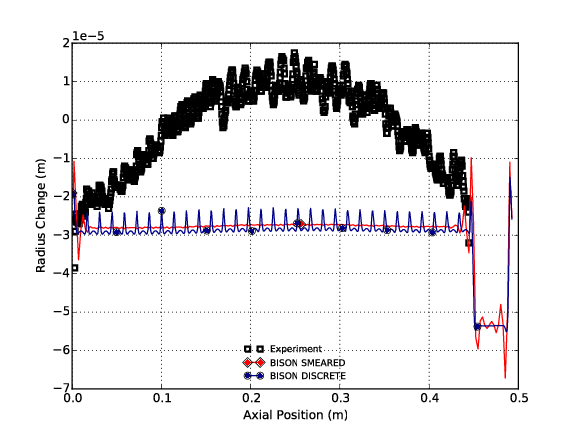
Figure 6: BISON rod diameter comparisons to experimental measurements before and after the power ramp.
Results Comparison
Fission Gas Release
BISON over predicts FGR after the base irradiation in the Gravlines 5 PWR and under predicts the FGR at the end of the ramp test. The comparisons are plotted in Figure 5.
Clad Diameter
BISON over predicts clad creep down which results in a smaller diameter than measured during PIE. The BISON comparisons to experimental measurements before and after the ramp are shown in Figure 6.
References
- IAEA.
Fuel Modelling at Extened Burnup (FUMEX-II): Report of a Coordinated Research Project 2002-2007.
Technical Report IAEA-TECDOC-1687, International Atomic Energy Agency, 2002-2007.[BibTeX]
- M. Limbäck and T. Andersson.
A model for analysis of the effect of final annealing on the in- and out-of-reactor creep behavior of zircaloy cladding.
In Zirconium in the Nuclear Industry: Eleventh International Symposium, ASTM STP 1295, 448–468. 1996.[BibTeX]