AREVA Idealized Case
Overview
The AREVA Idealized Case is an optimal case designed to simulate idealized commercial power plant operation. This case was based on measurements for three rods operatedf or 3, 4, and 7 cycles in a commercial French pressurized water reactor (PWR). The three rods chosen experienced similar power histories, allowing for three fission gas release measurements for a single power history. The maximum fuel rod burnup is approximately 81.5 MWd/kgU with a total fission gas release of approximately 9% (IAEA, 2008-2012).
Test Description
Rod Design Specifications
The rod simulated for this particular case was based on an idealized commercial reactor fuel rod. Details of the rod geometry and specifications are summarized in Table 1.
Table 1: AREVA Idealized Case Test Rod Specifications
| Fuel Rod | ||
|---|---|---|
| Fuel stack length | 3.65 | m |
| Nominal plenum volume | 8.04 | cm |
| Number of pellets per rod | 275 | |
| Fill gas composition | He | |
| Fill gas pressure | 1.6 | MPa |
| Fuel | ||
| Material | UO | |
| Enrichment | 4.5 | |
| Density | 95 | |
| Outer diameter | 8.085 | mm |
| Pellet geometry | dished | |
| Grain diameter | 15.6 | m |
| Pellet Dishing (if applicable) | ||
| Dish diameter | 6.0 | mm |
| Dish depth | 0.31 | mm |
| Chamfer width | 0.5425 | mm |
| Chamfer depth | 0.27 | mm |
| Cladding | ||
| Material | Zr-4 (stress-relieved) | |
| Outer diameter | 9.5 | mm |
| Inner diameter | 8.25 | mm |
| Wall thickness | 0.625 | mm |
Operating Conditions and Irradiation History
The operating conditions for this simulation were based on power cycles in a commercial French PWR. The operating conditions used are shown in Table 2.
Table 2: Operational input parameters.
| Coolant inlet temperature | C | 282 |
| Coolant pressure | MPa | 15.5 |
| Coolant mass flow rate | kg/m-sec | 3700 |
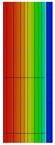
Figure 1: Section of BISON mesh with temperature contour.
Model Description
Geometry and Mesh
The fuel rod geometry specified in Table 1 was used as a basis for the mesh used in this simulation. The fuel pellets were meshed as a single smeared fuel column. The mesh consists of 1375 axial elements and 12 radial elements in the fuel, and 1375 axial elements and 4 radial elements in the clad, see Figure 1. This simulation was meshed as a 2D-RZ axisymmetric geometry with quadratic elements.
Material and Behavioral Models
The following material and behavioral models were used for the UO fuel:
UO2Thermal - NFIR: For temperature and burnup dependent thermal properties.
ComputeFiniteStrainElasticStress and UO2ElasticityTensor: elastic mechanical behavior
UO2VolumetricSwellingEigenstrain: volumetric expansion due to solid and gaseous swelling
UO2RelocationEigenstrain: relocation strains, relocation activation threshold power set to 5 kW/m
ComputeThermalExpansionEigenstrain:thermal expansion with a constant instanteous thermal expansion coefficient
UO2Sifgrs: fission gas release model used with the gaseous swelling model
UO2VolumetricSwellingEigenstrain
For the clad material, a constant thermal conductivity of 16 W/m-K was used and both thermal and irradiation creep were considered using the Limback model (Limbäck and Andersson, 1996). The following material and thermal behavior models were used for the cladding:
HeatConductionMaterial: Thermophysical material properties
ZryCreepLimbackHoppeUpdate and ZryElasticityTensor: mechanical creep and elastic deformation behavior for Zircaloy-2
ZryIrradiationGrowthEigenstrain: ESCORE model for volumetric swelling due to irradiation exposure
ZryThermalExpansionMATPROEigenstrain: thermal expansion of Zircaloy with the MATPRO model
Boundary and Operating Conditions
The power history used for this simulation is shown in Figure 2, with axial peaking factors shown in Figure 3. The average fast neutron flux was input as a function as well and is shown in Figure 4 with axial peaking factors shown in Figure 5. The clad temperature was calculated using the coolant channel model.
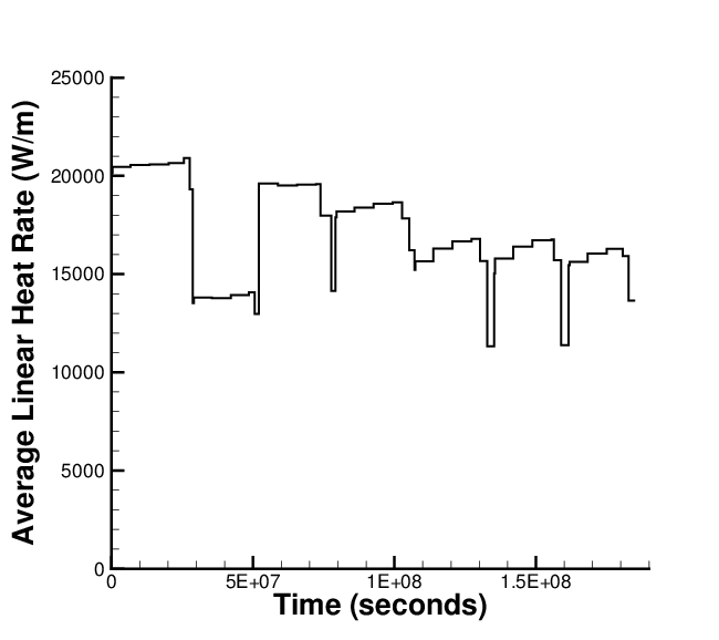
Figure 2: BISON input power history for the AREVA Idealized Case.
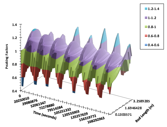
Figure 3: BISON input power axial peaking factors for the AREVA Idealized Case.
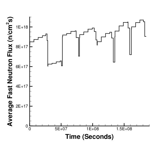
Figure 4: BISON input average fast neutron flux for the AREVA Idealized Case.
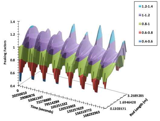
Figure 5: BISON input fast neutron flux axial peaking factors for the AREVA Idealized Case.
Input files
The BISON input and all supporting files (power histories, axial power profile, fast neutron flux history, etc.) for this case are provided with the code distribution at bison/assessment/LWR/benchmark/AREVA_idealized_case/analysis.
Results Comparison
Fission Gas Release
The expected fission gas release values are shown in Table 3 (IAEA, 2008-2012).
Table 3: Expected FGR values.
| End of cycle | Insertion time (d) | Burnup (MWd/kg(HM)) | Expected FGR value (%) |
|---|---|---|---|
| 3 | 916.4 | 36.6 | 0.5+0.5/-0.2 |
| 4 | 1239.1 | 49.7 | 1.9+1.0/-0.7 |
| 7 | 2141.9 | 81.5 | 9.0+2.5/-2.0 |
BISON predicts the total fission gas release reasonably well during the early and mid-burnup regimes, however FGR is under predicted at high burnup. BISON also compares well with other well known fuel performance codes, see Figure 6.
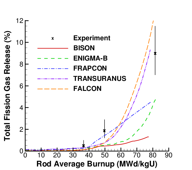
Figure 6: BISON predicted fission gas release in comparison to measured data and multiple fuel performance codes (code data digitized from FUMEX-III report (IAEA, 2008-2012)).
Discussion
Fuel creep was not modeled at this time. Fuel creep will be considered upon availablitly of some type of fuel cracking model.
References
- IAEA.
Improvement of Computer Codes Used for Fuel Behaviour Simulation (FUMEX-III): Report of a Coordinated Research Project 2008-2012.
Technical Report IAEA-TECDOC-1697, International Atomic Energy Agency, 2008-2012.[BibTeX]
- M. Limbäck and T. Andersson.
A model for analysis of the effect of final annealing on the in- and out-of-reactor creep behavior of zircaloy cladding.
In Zirconium in the Nuclear Industry: Eleventh International Symposium, ASTM STP 1295, 448–468. 1996.[BibTeX]