2D vs 3D Thermal Comparisons for BISON
Overview
The purpose of this study was to investigate the differences between 2D and 3D simulations. A simple thermal simulation was completed with three different mesh densities using linear and quadratic elements. The 2D and 3D results were compared to an analytical solution and the results are reported herein.
Test Description
A single pellet with a diameter of 8.2 mm and a length of 6 mm was modeled without cladding. Three different mesh densities were used for this comparison. They include, for the 2D simulations, a coarse mesh (6 radial elements and 2 axial elements), a medium mesh (11 radial elements and 3 axial elements), and a fine mesh (22 radial elements and 5 axial elements). The 3D meshes have the same radial and axial elements as the 2D with 6 circumferential elements for the coarse mesh, 12 circumferential elements for the medium mesh, and 24 circumferential elements for the fine mesh. These mesh densities are the default parameters in the BISON mesh script. The 2D meshes are shown in Figure 1 and the 3D meshes are shown in Figure 2.
A constant heat source of 400 W/cm was applied to the fuel pellet with a thermal conductivity of 5.2 W/m/K, and the outer edge of the fuel was set to a constant temperature of 500 K. The comparisons are performed for the fuel centerline temperature and power.
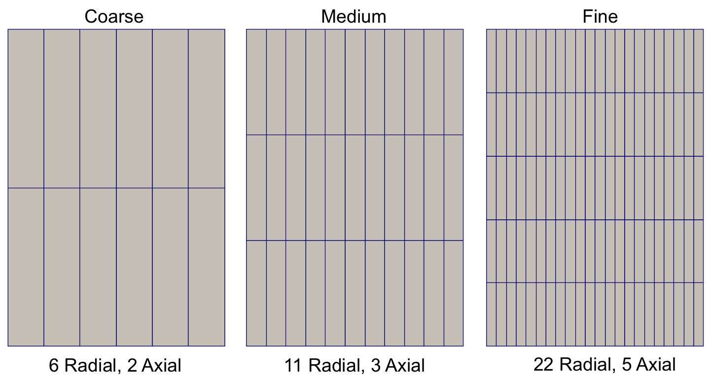
Figure 1: BISON default 2D meshes.
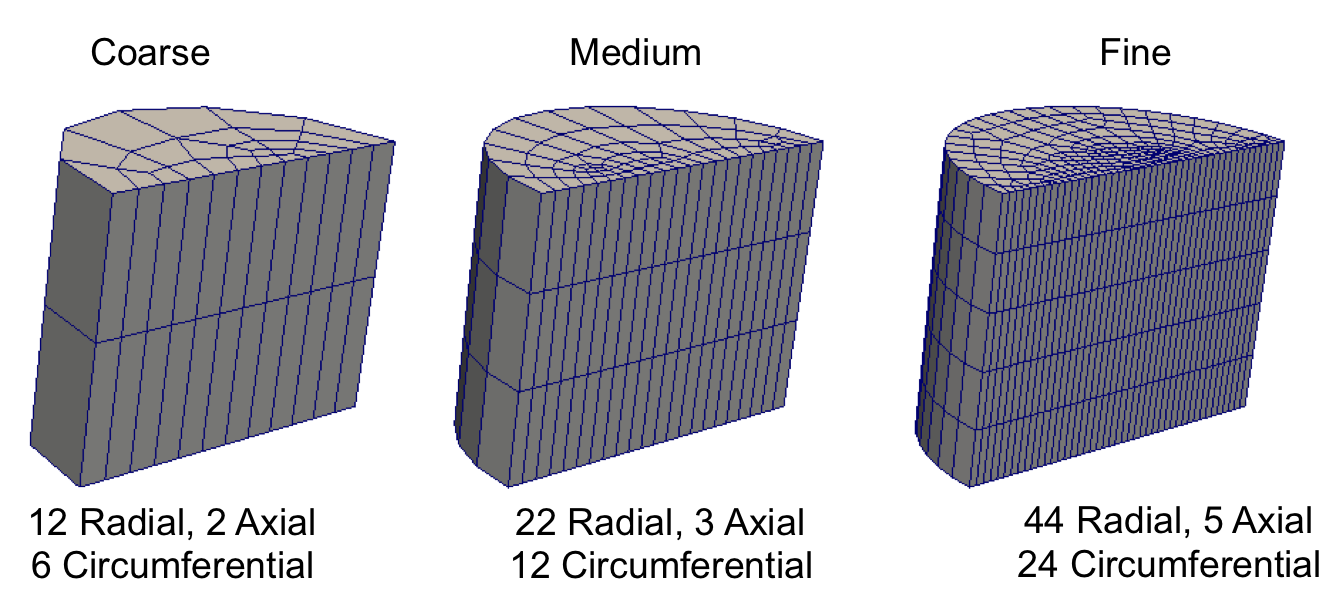
Figure 2: BISON default 3D meshes.
Results Comparison
This comparison was done with both linear and quadratic elements. Twelve simulations were ran; six linear and six quadratic. Using the parameters described in the previous section, the fuel centerline temperature is 823.27 K. The linear comparisons are shown in Table 1, the quadratic comparisons are shown in Table 2.
Table 1: Fuel centerline temperature and power for 2D and 3D linear meshes.
| Center Temp (K) | diff (%) | Power (W/m) | diff (%) | |
|---|---|---|---|---|
| Coarse 2D RZ | 828.89 | -0.6829 | 4.000e+08 | -0.0000 |
| Medium 2D RZ | 823.83 | -0.0683 | 4.000e+08 | -0.0000 |
| Fine 2D RZ | 823.83 | -0.0683 | 4.000e+08 | -0.0000 |
| Coarse 3D | 806.03 | 2.0944 | 3.820e+08 | 4.5070 |
| Medium 3D | 822.51 | 0.0919 | 3.989e+08 | 0.2853 |
| Fine 3D | 822.51 | 0.0919 | 3.989e+08 | 0.2853 |
Table 2: Fuel centerline temperature and power for 2D and 3D linear meshes.
| Center Temp (K) | diff (%) | Power (W/m) | diff (%) | |
|---|---|---|---|---|
| Coarse 2D RZ | 823.27 | 0.0000 | 4.000e+08 | -0.0000 |
| Medium 2D RZ | 823.27 | -0.0000 | 4.000e+08 | -0.0000 |
| Fine 2D RZ | 823.27 | -0.0000 | 4.000e+08 | -0.0000 |
| Coarse 3D | 823.28 | -0.0015 | 3.999e+08 | 0.0155 |
| Medium 3D | 823.27 | -0.0001 | 4.000e+08 | 0.0010 |
| Fine 3D | 823.27 | -0.0000 | 4.000e+08 | 0.0001 |
Based off the results shown, a linear mesh is not recommended for use in fuel performance modeling in 2D-RZ or 3D simulations. A coarse 3D mesh is not recommended for use as the faceting effect does not capture the full/actual volume causing the power mapping to be incorrect. A fine 3D mesh captures the power mapping well but can be computationally expensive. It is recommended that, in either 2D-RZ or 3D simulations, a medium quadratic mesh be used to properly capture the temperature gradient and the power (in 3D).