JOYO Experiments
Overview
Two uranium–plutonium UN fuel pins with different He-gap widths were irradiated at a linear heating rate 75 kW/m to 4.3% FIMA in the experimental fast reactor JOYO MK-II, and nondestructive and destructive post irradiation examinations were carried out. The UN pellets were loaded into 15Cr-20Ni stainless steel cladding tubes, irradiated in a fast-test reactor, JOYO, and destructively examined after reaching a burnup of 4.3% FIMA (fraction of initial metal atom). Pin geometry, irradiation conditions, fuel swelling, fission-gas release, and microstructural data were published in Tanaka et al. (2004).
Test Description
The JOYO test consisted of two helium-bonded MN pins (L413 and L414) that were irradiated in the experimental fast reactor JOYO to investigate the role of gap size on pin swelling. Subsequently, nondestructive and destructive post irradiation examinations were carried out in hot cells. In particular, fission gas and swelling behavior during irradiation were investigated in detail (Tanaka et al., 2004). These two pins are listed as assessment cases in BISON for MN fuel. The L413 and L414 pins had the same rod design and similar irradiation condition with only the gap size and a slightly different position in the test reactor varying between the two.
Rod Design Specifications
The fuel was solid cylindrical pellets of MN positioned between insulator and reflective pellets in 15Cr-20Ni stainless steel cladding tubes. Table 1 lists the rod design specifications specifying if the value comes from a direct measurement or was unknown and had to be estimated or calculated.
Table 1: SP-1 Rod Geometry
| Parameter | Value | Units | Source |
|---|---|---|---|
| Bonding | He | Tanaka et al. (2004) | |
| Pin length | 1486 | mm | Unknown, fixed as in JOYO-B14 (Maeda et al., 2011; Ikusawa et al., 2017) |
| Clad material | 15Cr-20Ni SS | Tanaka et al. (2004) | |
| Clad OD | 8.50 | mm | Tanaka et al. (2004) |
| Clad ID | 7.60 | mm | Tanaka et al. (2004) |
| Clad thickness | 0.45 | mm | Tanaka et al. (2004) |
| Diametral gap - L413 | 0.32 | mm | Tanaka et al. (2004) |
| Diametral gap - L414 | 0.17 | mm | Tanaka et al. (2004) |
| Smear density - L413 | 77.8 | %TD | Tanaka et al. (2004) |
| Smear density - L414 | 82.2 | %TD | Tanaka et al. (2004) |
| Pellet diameter - L413 | 7.28 | mm | Tanaka et al. (2004) |
| Pellet diameter - L414 | 7.43 | mm | Tanaka et al. (2004) |
| Pellet height | ~8 | mm | Tanaka et al. (2004) |
| Fuel stack - L413 | 200.1 | mm | Tanaka et al. (2004) |
| Fuel stack - L414 | 198.8 | mm | Tanaka et al. (2004) |
| Bulk density - L413 | 84.8 | %TD | Tanaka et al. (2004) |
| Bulk density - L414 | 86.0 | %TD | Tanaka et al. (2004) |
| Fuel Composition | |||
| Pu/(U+Pu) | 18.6 | wt% | Tanaka et al. (2004) |
| U235-enrichment | 19.39 | wt% | Tanaka et al. (2004) |
| N/M ratio - L413 | 1.00 | - | Tanaka et al. (2004) |
| N/M ratio - L414 | 1.01 | - | Tanaka et al. (2004) |
| Top/bottom plug | 4.8 | mm | Unknown, fixed as in MTR-SNAP50 |
| Bottom gap under pellet | 375 | mm | Estimated based on Fig. 4 in Tanaka et al. (2004) |
| Plenum height - L413 | 901.3 | mm | Calculated (Pin length-Fuel stack-2*Top/bottom plug-Bottom gap under pellet) |
| Plenum height - L414 | 902.6 | mm | Calculated (Pin length-Fuel stack-2*Top/bottom plug-Bottom gap under pellet) |
| Fill gas pressure | 0.1 | MPa | Unknown, fixed equal to what is used in JOYO-B14 (Maeda et al., 2011; Ikusawa et al., 2017) |
Note that due to the currently limited information about the insulator and reflective pellets used in this experiment, they are currently not modeled in the BISON assessment cases.
Operating Conditions and Irradiation History
The actual power history for specific JOYO MK-II experiments is still being determined. Therefore, a simplified power history containing an initial ramp to power and hold for a given amount of time with a final power down is being used. The average burnup of the fuel at the end of the simulation is used as a check that the power history is reasonable. The parameters for the irradiation and temperature history are detailed in Table 2. Using an average linear heating rate of 70 kW/m, the final burnup reached in the BISON simulations is around 4.5 % FIMA (4.7 % FIMA for L413, and 4.4 % FIMA for L414).
The exact temperature history is also still being determined. In the meantime, the initial temperature is fixed to 298 K, and the temperature ramps up to the desired profile for the irradiation time before ramping down at the end of the simulation.
Table 2: SP-1 Operating Conditions
| Parameter | Value | Units | Source |
|---|---|---|---|
| Fast neutron flux | n cm s | Aoyama et al. (2004) | |
| Max linear heating rate | 75 | kW/m | Tanaka et al. (2004) |
| Average linear heating rate | 70 | kW/m | Tanaka et al. (2004) |
| Burnup | ~4.3 | % FIMA | Tanaka et al. (2004) |
| Irradiation duration | 276 | Equivalent full power days | Tanaka et al. (2004) |
| Inlet temperature | 643.15 | K | Nomoto et al. (1980) and Aoyama et al. (2004) |
| Outlet temperature | 773.15 | K | Aoyama et al. (2004) |
| Average cladding temperature | 900 | K | Estimated |
Note that since the burnup [Material] block does not currently account for fuel enrichment, the full effect of the fuel enrichment in Pu and U-235 on burnup is not yet accounted for. This will need to be updated. Similarly, Tanaka et al. (2004) provides the linear heating rate as a function of burnup, which varies from 75 kW/m to below 65 kW/m. Currently, the linear heating rate is assumed to be fixed at 70 kW/m. This could also be updated once the burnup is updated.
Model Description
The L413 and L414 pins are modeled in BISON using a base input file titled JOYO_Pin_base.i (either with the full input file or using the action to create the necessary blocks), a file titled JOYO_Pin_options.i containing the information common to the three pins (e.g., rod design, irradiation conditions, etc.), and files containing the information specific to each pin, titled JOYO_Pin_options_L413.i, and JOYO_Pin_options_L414.i.
The specifications and conditions for all three pins are described below. Note that only the pins are being modeled, not the L4C4 compartment or the PFB090 fuel assembly.
Temperature Profile
Since the exact temperature profile on the surface of the cladding is unknown, it is assumed to follow a second degree polynomial with being the position along the cladding, and , , and constants defined to reproduce the provided inlet, outlet, and average temperatures in Kelvins provided in Table 2, as shown in Figure 1. To define the temperature profile, the average cladding temperature is estimated as provided in Table 2.
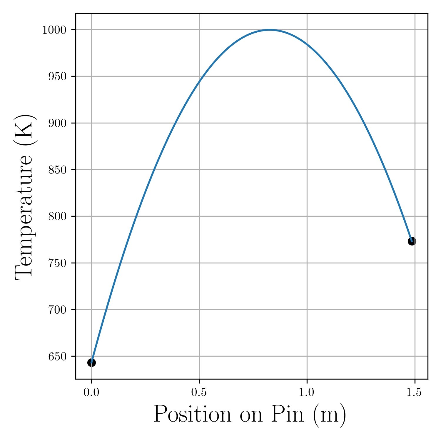
Figure 1: Temperature profile used to model L413 and L414 with informed inlet and outlet temperatures.
Power Profile
The exact power profile for these tests is still unknown. For now, as for the modelization of the JOYO MK-II Core, the FFTF power profile shown in Figure 2 is being used (Karahan, 2009).
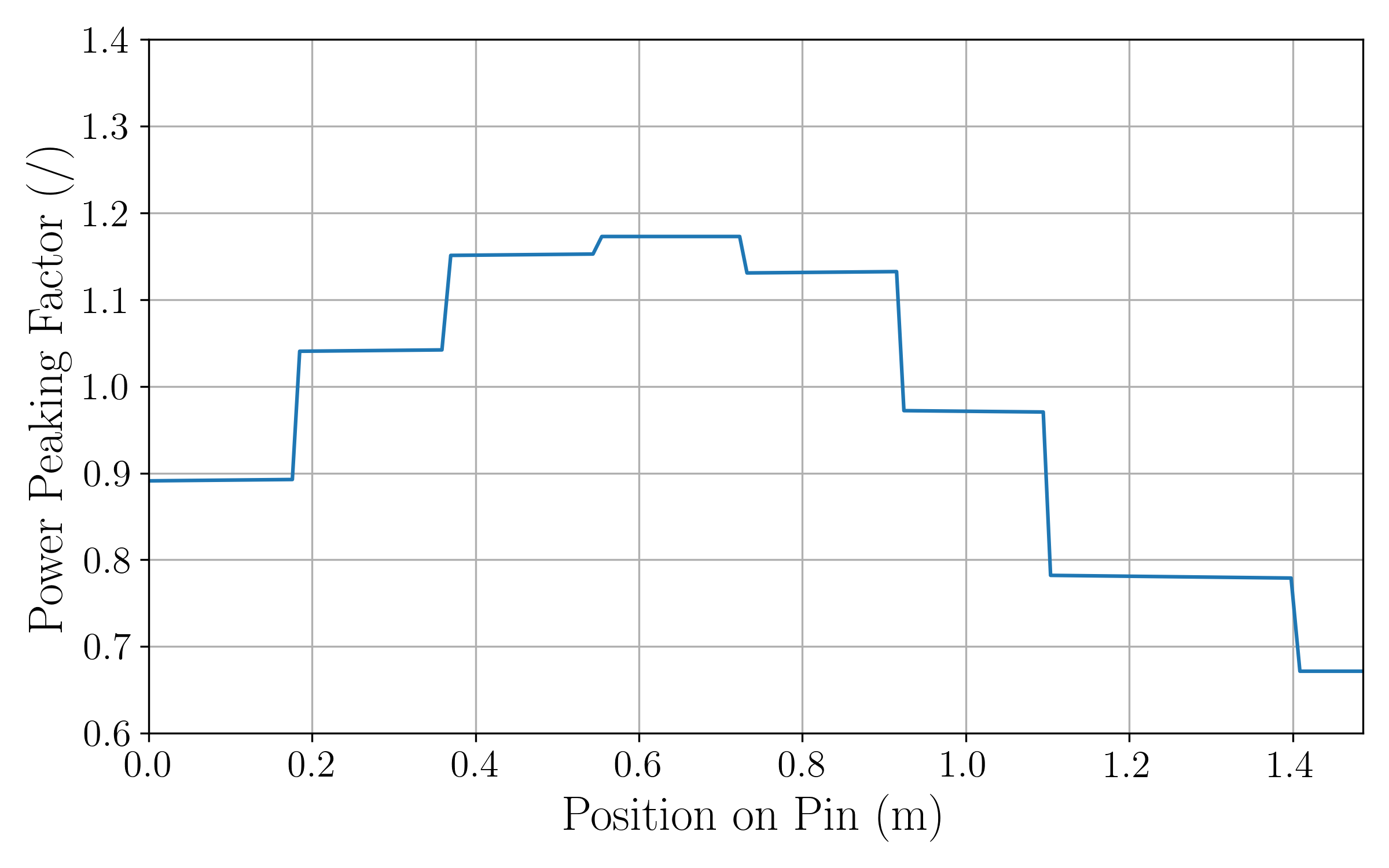
Figure 2: Power peaking factors for FFTF and used for MK-II cores (Karahan, 2009).
Pressure Profile
The coolant pressure is unknown for now. The coolant is made out of sodium, and the pressure is assumed to be equal to 15.1 MPa.
Geometry and Mesh
The 2D-RZ mesh for the assessment case is generated with the internal smeared pellet meshing capability in BISON FuelRPinMeshGenerator.
All of the dimensions and meshing details are contained in the [Mesh] block.
Material and Behavioral Models
The following material and behavioral models for the MN fuel were used:
MNElasticityTensor: Computes Young's modulus and Poisson's ratio for MN fuel
MNThermalExpansionEigenstrain: Computes an eigenstrain due to thermal expansion for MN fuel
MNCreepUpdate: Creep mechanical properties and deformation behavior for MN fuel
MNThermal: Calculates the thermal conductivity and specific heat for MN fuel
MNThermalExpansionEigenstrain: Calculates thermal expansion coefficient and isotropic expansion for MN fuel
MNVolumetricSwellingEigenstrain: Computes swelling due to solid and gaseous fission products for MN fuel
The following material and behavioral models are used for the 15Cr-20Ni stainless steel cladding. Note that due to the current lack of property data on 15Cr-20Ni stainless, the properties of SS316 are currently used:
SS316ElasticityTensor: Temperature-dependent Young's modulus and constant Poisson's ratio ()
SS316ThermalExpansionEigenstrain: Eigenstrain due to thermal expansion for Stainless Steel 316 using a function that describes the mean thermal expansion as a function of temperature
SS316CreepUpdate: Steady state creep as sum of thermal and irradiation creep following Altenbach and Gorash (2013) and Garner and Porter (1988)
SS316Thermal: Thermophysical material properties
To compute the density of SS316, a
DerivativeParsedMaterialprovides in kg/m, which is valid for T in Kelvin for 298.15 K T 1573.15 K (Mills, 2002)).
Note that thermal and mechanical contacts are modeled using mortar contact.
Input files
The input files for these assessment cases are located at bison/assessment/nitride/JOYO/J4C4/analysis.
To run the assessment cases, the input files and option files need to be combined into one by listing them in the command. For example, to run the assessment case for pin L413, one should list JOYO_Pin_options_L413.i JOYO_Pin_options.i JOYO_Pin_base.i, or JOYO_Pin_options_L413.i JOYO_Pin_options.i JOYO_Pin_base_action.i to use the action.
Results Comparison
The post-irradiation examinations (PIE) of the JOYO - L413 and JOYO - L414 pins provide the measurements listed in Table 3 and Table 4, respectively (Tanaka et al., 2004). The profilometry results provided in Tanaka et al. (2004) are reproduced in figure Figure 3. The profilometry data shown in figure Figure 3 is available in csv files titled JOYO_L413_profilometry_data_A-C.csv, JOYO_L413_profilometry_data_B-D.csv, JOYO_L413_profilometry_data_Average.csv, and JOYO_L414_profilometry_data_A-C.csv, JOYO_L414_profilometry_data_B-D.csv, JOYO_L414_profilometry_data_Average.csv.
Table 3: PIE data for JOYO - L413
| Quantity | Measurements | Units | Source |
|---|---|---|---|
| FGR Xe | Unknown | ||
| FGR Kr | Unknown | ||
| FGR total | 3.3 | % | Tanaka et al. (2004) |
| Fuel swelling V/V | 7.4 | % | Tanaka et al. (2004) |
| Max cladding strain D/D | 0.17 | % | Tanaka et al. (2004) |
| Fuel density decrease | 5.8 | % | Tanaka et al. (2004) |
| Change in cladding length | Unknown | ||
| Open porosity | 4.2 | % | Tanaka et al. (2004) |
| Closed porosity | 16.8 | % | Tanaka et al. (2004) |
Table 4: PIE data for JOYO - L414
| Quantity | Measurements | Units | Source |
|---|---|---|---|
| FGR Xe | Unknown | ||
| FGR Kr | Unknown | ||
| FGR total | 5.2 | % | Tanaka et al. (2004) |
| Fuel swelling V/V | 6.7 | % | Tanaka et al. (2004) |
| Max cladding strain D/D | 0.51 | % | Tanaka et al. (2004) |
| Fuel density decrease | 5.4 | % | Tanaka et al. (2004) |
| Change in cladding length | Unknown | ||
| Open porosity | 4.1 | % | Tanaka et al. (2004) |
| Closed porosity | 15.3 | % | Tanaka et al. (2004) |
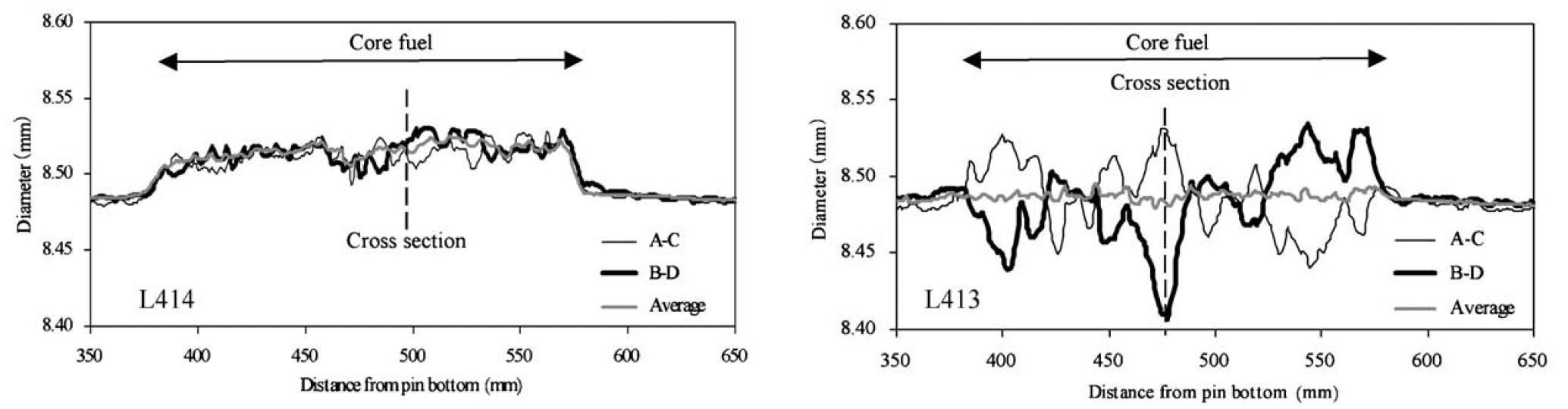
Figure 3: Profilometry Results for L413 and L414 (Tanaka et al., 2004). A, B, C, and D are points on the outer diameter of the cladding positioned at 0, 90, 180, and 270 degrees, respectively.
The radial distribution of the area fraction of pores and the measured Xe content is also provided in Tanaka et al. (2004) for L414.
Discussion
The BISON simulation results have not yet been compared to the post-experiment examinations data.
References
- Holm Altenbach and Yevgen Gorash.
High-temperature inelastic behavior of the austenitic steel aisi type 316.
In Advanced Materials Modelling for Structures, pages 17–30.
Springer, 2013.[BibTeX]
- Takafumi Aoyama, Takashi Sekine, and Shiro Tabuchi.
Characterization of neutron field in the experimental fast reactor joyo for fuel and structural material irradiation test.
Nuclear Engineering and Design, 228:21–34, 3 2004.
doi:10.1016/J.NUCENGDES.2003.06.003.[BibTeX]
- FA Garner and DL Porter.
Irradiation creep and swelling of aisi 316 to exposures of 130 dpa at 385-400 c.
Journal of Nuclear Materials, 155:1006–1013, 1988.[BibTeX]
- Yoshihisa Ikusawa, Koji Maeda, Masato Kato, and Masayoshi Uno.
Oxide-metal ratio dependence of central void formation of mixed oxide fuel irradiated in fast reactors.
Nuclear Technology, pages 83–95, 2017.[BibTeX]
- Aydin Karahan.
Modeling of thermo-mechanical and irradiation behavior of metallic and oxide fuels for sodium fast reactors.
PhD thesis, Massachusetts Institute of Technology, Jun 2009.
URL: https://tinyurl.com/y72vqvbn.[BibTeX]
- K. Maeda, K. Katsuyama, Y. Ikusawa, and S. Maeda.
Short-term irradiation behavior of low-density americium-doped uranium-plutonium mixed oxide fuels irradiated in a fast reactor.
Journal of Nuclear Materials, 416(1-2):158–165, Sep 2011.[BibTeX]
- K. C. Mills.
Recommended Values of Thermophysical Properties for Selected Commercial Alloys.
Technical Report, National Physical Laboratory, 2002.[BibTeX]
- S. Nomoto, H. Yamamoto, Y. Sekiguchi, and S. Tamura.
Measurement of subassembly outlet coolant temperature in the joyo experimental fast reactor.
Nuclear Engineering and Design, 62:233–239, 12 1980.
doi:10.1016/0029-5493(80)90031-X.[BibTeX]
- Kosuke Tanaka, Koji Maeda, Kozo Katsuyama, Masaki Inoue, Takashi Iwai, and Yasuo Arai.
Fission gas release and swelling in uranium–plutonium mixed nitride fuels.
Journal of Nuclear Materials, 327:77–87, 5 2004.
doi:10.1016/J.JNUCMAT.2004.01.002.[BibTeX]