EBR-II WSA-32 Experiment
Overview
The WSA-32 experiment in EBR-II contained a series of mixed uranium-plutonium carbide fuel pins run to high burnup (12 at.%) at high power (100 kW/m) over the period from 1976-1981. The WSA-32 test contained 19 pins operated at the expected midplane peak power for a hypothetical 91-pin assembly in the Fast Flux Test Facility. Post-irradiation analysis included profilometry, fission gas release, and ceramographic/microsturctural examination.
Test Description
The WSA-32 experiment consisted of 19 helium-bonded pins, 5 of which were replaced with fresh pins after a burnup of 8.6%. The design parameters that were varied were the pellet densities and the diametral gap sizes. The irradiation reached peak burnup of 12%.
Rod Design Specifications
The fuel was solid cylindrical pellets of (UPu)C with sesquicarbide content of 105 volume percent and 79.3% enriched uranium content. The pellet densities were 81 and 87% TD and the diametral gap sizes were 0.15 and 0.28 mm, resulting in smear densities of 76, 78, and 81% (87% TD pellets were not used in the smaller gap configuration). The pellets were encased in 316 SS clad and wire-wrapped with a 1.7 mm diameter spacer, also in 316 SS.
The plenum volume according to Blank (2006) is 2.4 cm, which results in a plenum height of just 43.5 mm. However, this number needs to be confirmed since it is inconsistent with other experiments in EBR-II, which typically had much longer fuel pins.
Table 1: WSA-32 Rod Geometry
| Parameter | Value | Units | Source |
|---|---|---|---|
| Clad material | 316 SS | Levine et al. (1981) | |
| Clad bonding | He | Levine et al. (1981) | |
| Clad OD | 9.40 | mm | Levine et al. (1981) |
| Clad thickness | 0.508 | mm | Levine et al. (1981) |
| Diametral gap | 0.15, 0.28 | mm | Levine et al. (1981) |
| Pellet diameter | 8.10, 8.23 | mm | Levine et al. (1981) |
| Fuel stack | 343 | mm | Blank (2006) |
| Plenum height | 43.5 | mm | Blank (2006), see discussion |
| Plenum pressure | 12.4 | MPa | Blank (2006) |
| Top/bottom gap | 8 | mm | unknown (estimated) |
| Smear density | 76, 78, 81 | %TD | Levine et al. (1981) |
Operating Conditions and Irradiation History
The actual power history for specific EBR-II experiments is still being determined. Therefore, a simplified power history containing an initial ramp to power and hold for a given amount of time with a final power down is being used. The average burnup of the fuel at the end of the simulation is used as a check that the power history is reasonable. The remaining parameters are in Table 2.
Table 2: WSA-32 Operating Conditions
| Parameter | Value | Units | Source |
|---|---|---|---|
| Coolant | 644 | K | Blank (2006) |
| Coolant | 746 | K | Blank (2006) |
| Average flux | 1.6 | n cm s | Blank (2006) |
| Peak power | 100-107 | kW/m | Blank (2006), Levine et al. (1981) |
| Burnup | 4-12 | at.% | Levine et al. (1981) |
Model Description
The test case simulates the W32-02 rod, which had a diametral gap of 0.29 mm and initial density of 88.1% TD according to profilimetry data, resulting in a smear density of 82.2. We simulated this rod because it has relatively low porosity, and some of the models in BISON have a limit of 15% porosity. The axial peaking factors and burnups for W32-02 are shown in Table 3.
Table 3: Rod WS32-02 Operating Conditions Levine et al. (1981)
| Axial position (x/L) | Linear power (kW/m) | Burnup (at.%) |
|---|---|---|
| 0.11 | 86.4 | 10.0 |
| 0.30 | 96.6 | 10.9 |
| 0.56 | 99.7 | 11.3 |
| 0.70 | 95.9 | 10.9 |
| 0.89 | 86.8 | 9.8 |
Geometry and Mesh
The 2D-RZ mesh for the test case is generated with the internal smeared pellet meshing capability in BISON FuelPinMeshGenerator. All of the dimensions and meshing details are contained in the Mesh block.
Material and Behavioral Models
This test case uses automatic differentiation. The following material and behavioral models for the (U,Pu)C fuel were used:
ADMCElasticityTensor: Computes Young's modulus and Poisson ratio for MC fuel
ADMCCreepUpdate: Creep mechanical properties and deformation behavior for MC fuel
ADMCThermal: Calculates the thermal conductivity and specific heat for MC fuel
ADMCThermalExpansionEigenstrain: Calculates thermal expansion coefficient and isotropic expansion for MC fuel
ADMCVolumetricSwellingEigenstrain: Computes swelling due to solid and gaseous fission products for MC fuel
The following material and behavioral models for the 316SS cladding were used in these cases:
ADComputeIsotropicElasticityTensor: Computes isotropic elastic mechanical properties for generic material
ADSS316Thermal: Calculates the thermal conductivity and specific heat for 316 SS
ADDensity: Computes density for generic material
This case demonstrates use of automatic differentiation (AD) with full (SMP) preconditioning. Therefore it is missing models for mechanical and thermal contact, which are not implemented yet. To simulate mechanical contact, a constant plenum pressure is applied to all pellet boundaries.
To simulate thermal contact, the steady-state radial heat flux is computed from the fission rate, and this flux is used to compute the clad and gap temperature drops. Since the Na coolant temperature is prescribed, the temperature at the pellet OD can then also be prescribed as a function of local coolant temperature and fission rate. This method avoids the ill-posed BC that would result from assigning a heat flux directly to pellet boundary.
Input files
The input file for the 2D-RZ case is located at bison/assessment/carbide/EBRII/WSA32/analysis.
Results
The fuel centerline temperature (FCT) depends fission rate in the pellets and on heat transfer characteristics such as conductivity in the pellet, gap, and clad, and on the coolant temperature. The peak FCT is shown over the irradiation history in Figure 1.
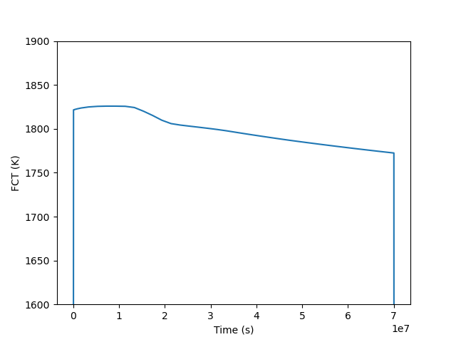
Figure 1: Maximum fuel centerline temperature throughout the irradiation history.
The change in the radius of the pellets depends on thermal expansion, creep, swelling, and elasticity. The change in pellet radius is shown at the end of the irradiation phase in Figure 2 and the maximal radius change over irradiation time is shown in Figure 3.
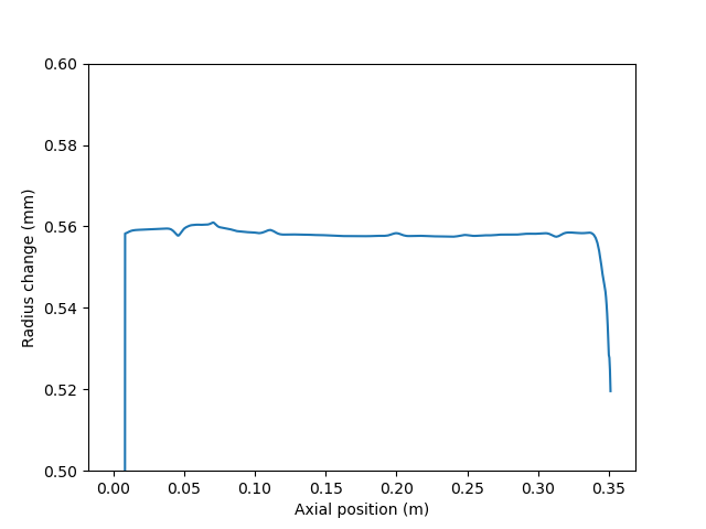
Figure 2: Change in pellet radius at end of irradiation before cool-down (at s).
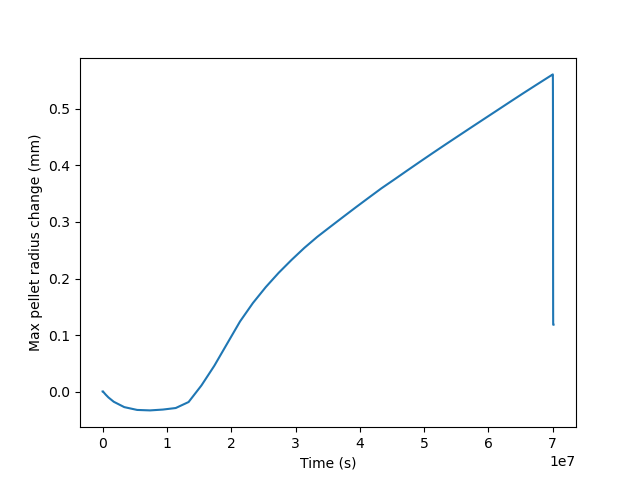
Figure 3: Maximal change in pellet radius throughout the irradiation history.
The outer radius of the fuel rod is not shown because there is no thermal or mechanical contact model available. Thus, the shape of the clad does not appreciably change during the simulation.
Discussion
Currently, this assessment case merely demonstrates the use of the carbide fuel models. The case is limited by models that have not yet been implemented and by available validation data. At this time, thermal and mechanical contact modules are not available for use in conjunction with AD material models. Additionally, porosity has been prescribed as a linear progression since a fission gas release (FGR) model has not yet been implemented. Critical properties such as swelling and creep depend heavily on thermo-mechanical contact between the fuel and the clad while porosity and FGR strongly affect both thermal conduction and mechanical performance.
Once these modeling shortcomings have been alleviated, simulations can be compared to available data on the EBRII experiment. Post-irradiation analysis included profilometry and FGR measurement; this data could be compared to final pellet radius and FGR from BISON simulations.
References
- Hubert Blank.
Nonoxide Ceramic Nuclear Fuels, chapter, pages.
John Wiley & Sons, Ltd, 2006.
URL: https://onlinelibrary.wiley.com/doi/abs/10.1002/9783527603978.mst0108, doi:10.1002/9783527603978.mst0108.[BibTeX]
- P.J. Levine, U.P. Nayak, and A. Boltax.
High burnup, high power irradiation behavior of helium-bonded mixed carbide fuel pins.
In Trans. 7th Int. Conf. on SMiRT, volume C5/2, 161–168. Chicago, 1981. North-Holland; Amsterdam.[BibTeX]