JOYO MK-I Core
Overview
MK-I core has been irradiated in the Japanese experimental fast reactor JOYO at 50 MWt and at 75 MWt from 1977 to 1981 (Shimada et al., 1986). JOYO was the first sodium cooled reactor leading the FBR development program in Japan. The MK-I core is composed by a maximum 80 driver assemblies surrounded by stainless steel reflectors.
Test Description
Rod Design Specifications
The fuel specifications for the MK-I core are summarized in Table 1.
Table 1: JOYO MK-I core specifications.
| Fuel Rod | Measurement | Unit |
|---|---|---|
| Fuel stack height | 600 | mm |
| Plenum - fuel ratio | 1 | |
| Fill gas composition | He | |
| Fill gas pressure | 0.3 | MPa |
| Fuel | Measurement | Unit |
| Material | MOX | |
| U 235 Enrichment | 23.0 | |
| PuO content | 18.0 | |
| Density | 93.5 | |
| Outer diameter | 5.4 | mm |
| Grain radius | 8 | m |
| Cladding | Measurement | Unit |
| Material | 316SS | |
| Outer diameter | 6.3 | mm |
| Inner diameter | 5.6 | mm |
| Wall thickness | 0.35 | mm |
| Pin pitch | 7.6 | mm |
Operating Conditions and Irradiation History
The base irradiation power history is shown in Figure 1 for the the operation at 50MWt and in Figure 2 for the experiment at 75MWt. The axial peak factors profile is shown in Figure 3. The coolant inlet temperature and pressure for the base irradiation is shown in Table 2.
Table 2: Operational input parameters.
| Unit | 50 MWt | 75 MWt | |
|---|---|---|---|
| Coolant inlet temperature | C | 370 | 370 |
| Coolant pressure | MPa | 0.101325 | 0.101325 |
| Primary coolant flow rate | t/h | 2200 | 2200 |
| Linear heat rate | kW/m | 21.0 | 32.0 |
| Max. burnup (pin av.) | GWd/t | 25 | 42 |
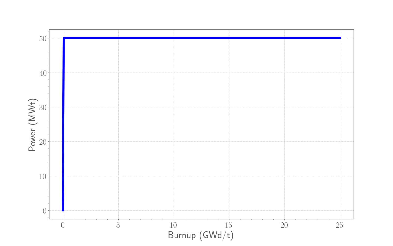
Figure 1: Base irradiation average power history for the 50MWt experiment of MK-I core .
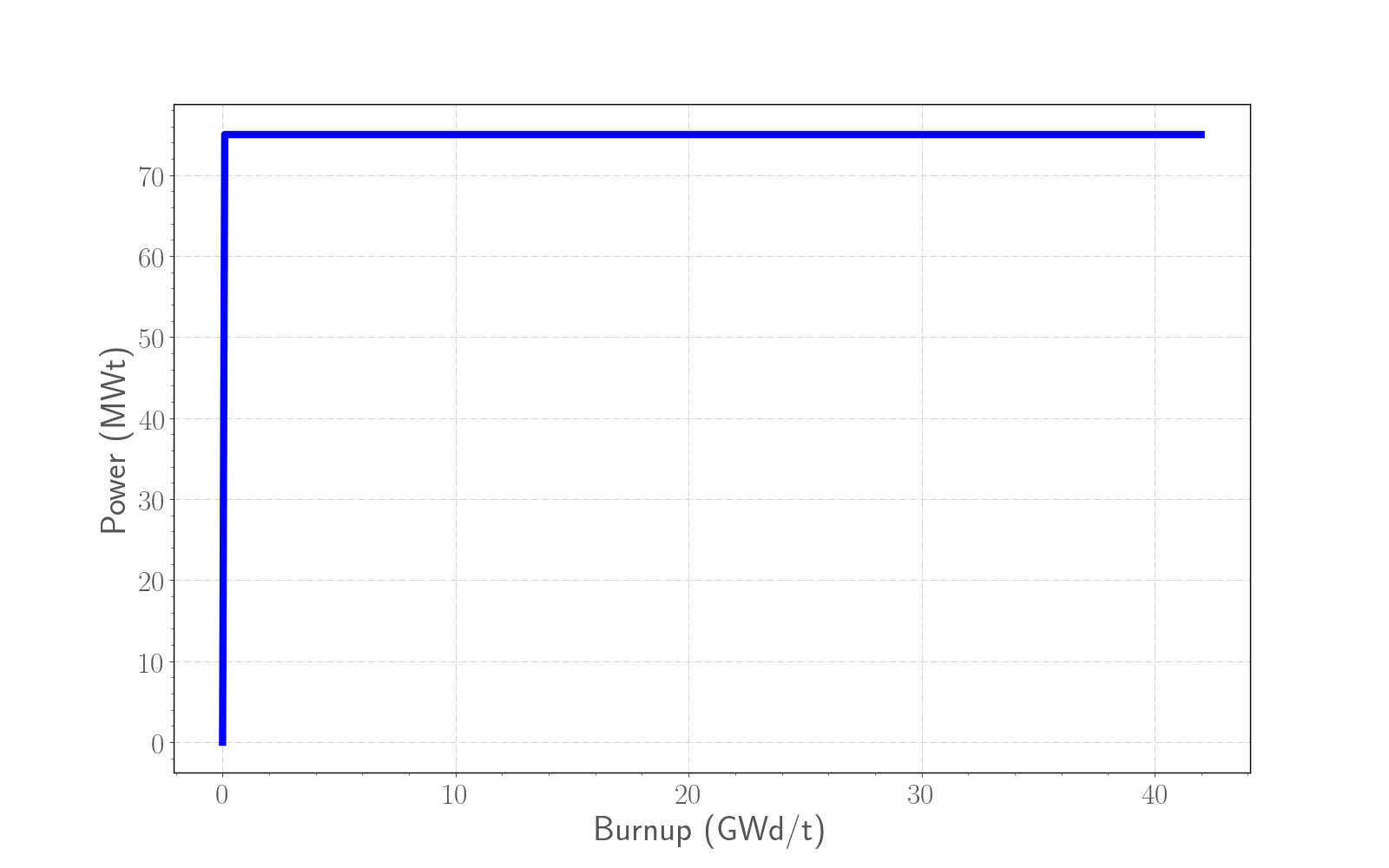
Figure 2: Base irradiation average power history for the 75MWt experiment of MK-I core .
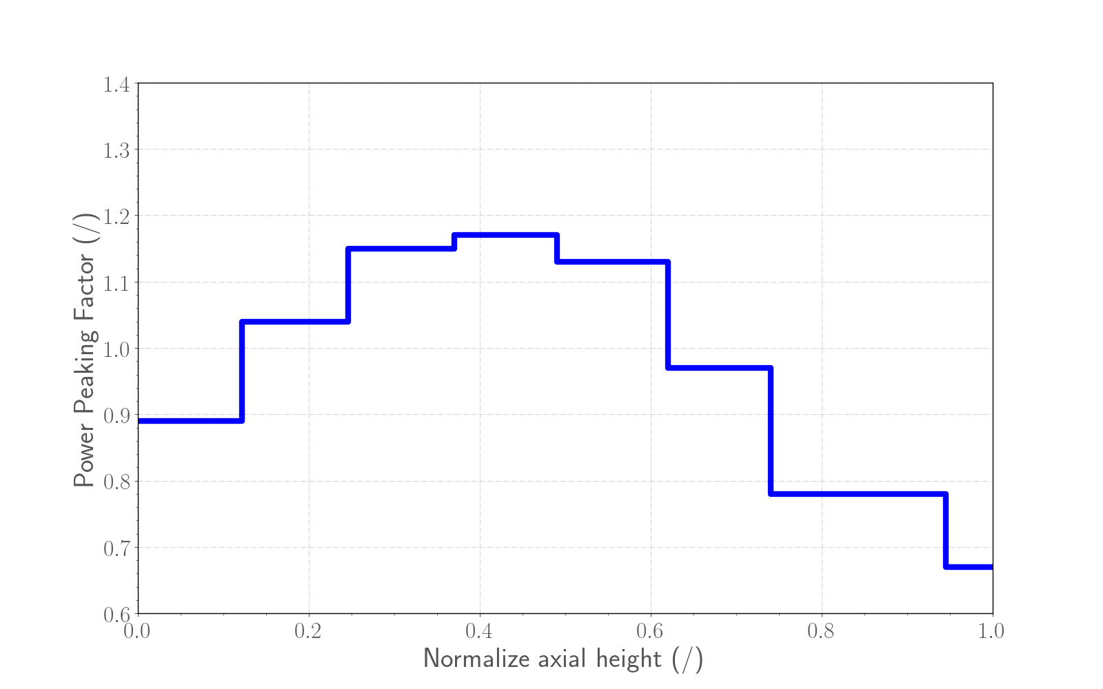
Figure 3: Power peaking factors for MK-I and MK-II cores from (Karahan, 2009).
Model Description
Geometry and Mesh
A generic rod from MK-I core was modeled as a smeared fuel pellet stack. The geometric parameters specified in Table 1 were used to create the meshes for these simulations. The smeared fuel was meshed as a single smeared fuel column with 20 radial elements and 200 axial elements. Figure 4 shows a section of the mesh with a temperature contour plot. This contour plot was made near the end of the run. Actual numbers are irrelevant in this case as this plot is only meant to show the discretization.
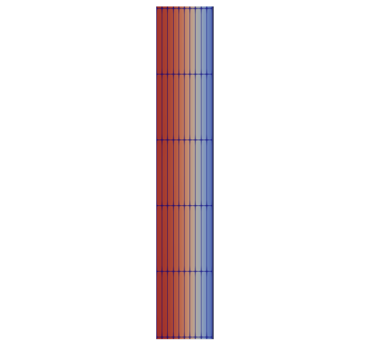
Figure 4: A section of the MK-I fuel rod mesh with a temperature contour plot.
Input files
The BISON input and all supporting files (power histories, axial power profile, fast neutron flux history, etc.) for this case are provided with the code distribution at bison/assessment/MOX/JOYO/MK-I/analysis.
Material and Behavioral Models
The following material and behavioral models for MOX fuel were used:
FissionRateMOX: model that takes into account of the pore migration for the fission rate calculations
MAMOXThermal: model for temperature and porosity dependent thermal properties
ComputeFiniteStrainElasticStress: elastic mechanical behavior
MAMOXElasticityTensor: constant values from JAEA are used for the two elastic constants Young's modulus ( Pa) and Poisson ratio ()
MAMOXThermalExpansionEigenstrain: isotropic thermal expansion's eigenstrain from (Kato et al., 2011) and (Kato et al., 2016)
UO2VolumetricSwellingEigenstrain: volumetric expansion due to solid and gaseous swelling
UO2Sifgrs: fission gas release model used with the gaseous swelling model UO2VolumetricSwellingEigenstrain (Pastore et al., 2015)
The following material and thermal behavior models were used for the cladding:
SS316Thermal: Thermophysical material properties
SS316ElasticityTensor: temperature-dependent Young's modulus and constant Poisson ratio ()
SS316ThermalExpansionEigenstrain: eigenstrain due to thermal expansion for Stainless Steel 316 using a function that describes the mean thermal expansion as a function of temperature
SS316CreepUpdate: steady state creep as sum of thermal and irradiation creep, following (Altenbach and Gorash, 2013) and (Garner and Porter, 1988)
Details and references for all of these models listed above can be found on the linked BISON documentation pages.
Results Comparison
Fission Gas Release
The calculated integral fuel rod FGR is compared to the measured data in Figure 5 for the experiment at 50 MWt and in Figure 6 for the 75 MWt experiment. BISON results with the recommended lower limit for the number density of grain boundary bubbles (10 bubbles/m) for FBR MOX fuels show a good agreement with the experimental data, in line with the intrinsic modeling uncertainties (Pastore et al., 2015).
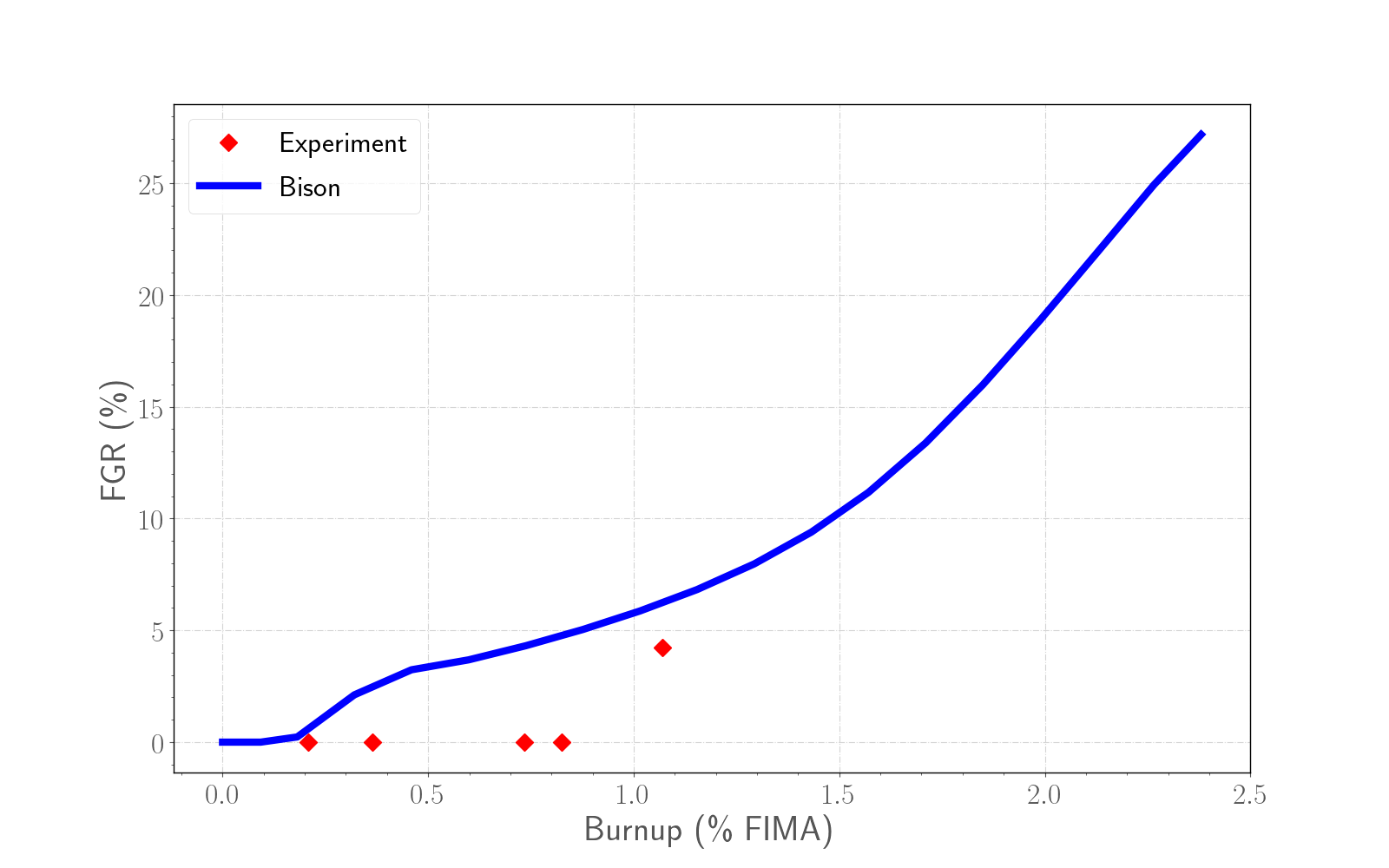
Figure 5: Fission gas release comparison for the experiment at 50 MWt among MK-I experimental data, BISON simulation using the previous lower limit for the number density of grain boundary bubbles (10 bubbles/m) used for UO and BISON simulation using the recommended lower limit for the number density of grain boundary bubbles (10 bubbles/m) for FBR MOX fuels.
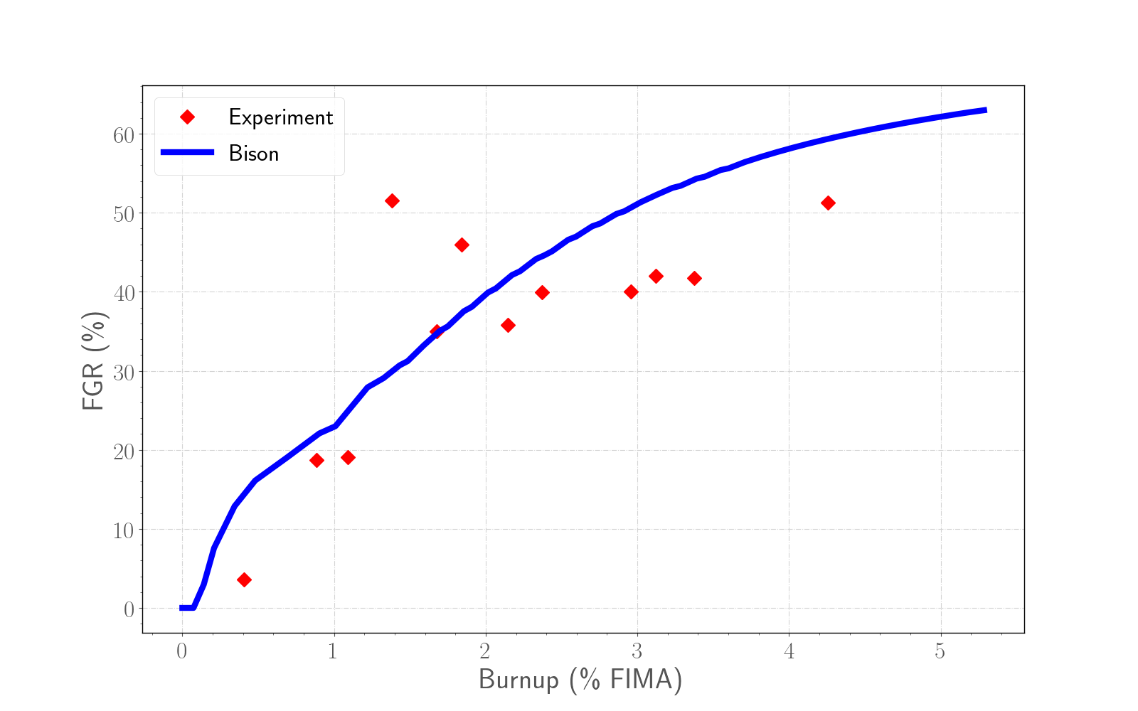
Figure 6: Fission gas release comparison for the experiment at 75 MWt among MK-I experimental data, BISON simulation using the previous lower limit for the number density of grain boundary bubbles (10 bubbles/m) used for UO and BISON simulation using the recommended lower limit for the number density of grain boundary bubbles (10 bubbles/m) for FBR MOX fuels.
Discussion
For fast MOX fuels, higher temperatures are reached compared to LWR fuels. The associated pronounced bubble growth and coalescence can lead to the attainment of the lower limit for the number density of grain boundary bubbles systematically. Preliminary simulations of FBR MOX irradiations have indicated that a value of leads to a more accurate result in terms of both FGR and swelling compared to the default LWR UO value. A value of is compatible with experimental observations, e.g., (White, 2004).
References
- Holm Altenbach and Yevgen Gorash.
High-temperature inelastic behavior of the austenitic steel aisi type 316.
In Advanced Materials Modelling for Structures, pages 17–30.
Springer, 2013.[BibTeX]
- FA Garner and DL Porter.
Irradiation creep and swelling of aisi 316 to exposures of 130 dpa at 385-400 c.
Journal of Nuclear Materials, 155:1006–1013, 1988.[BibTeX]
- Aydin Karahan.
Modeling of thermo-mechanical and irradiation behavior of metallic and oxide fuels for sodium fast reactors.
PhD thesis, Massachusetts Institute of Technology, Jun 2009.
URL: https://tinyurl.com/y72vqvbn.[BibTeX]
- M. Kato, Y. c, T. Sunaoshi, A. Nelson, and K. McClellan.
Thermal expansion measurement of $(U,Pu)O_2-x$ in oxygen partial pressure-controlled atmosphere.
Journal of Nuclear Materials, 469:223–227, 2016.[BibTeX]
- M. Kato, K. Maeda, T. Ozawa, M. Kashimura, and Y. Kihara.
Physical properties and irradiation behavior analysis of Np- and Am-bearing MOX fuels.
Journal of Nuclear Science and Technology, 48:646–653, 2011.[BibTeX]
- G. Pastore, L.P. Swiler, J.D. Hales, S.R. Novascone, D.M. Perez, B.W. Spencer, L. Luzzi, P. Van Uffelen, and R.L. Williamson.
Uncertainty and sensitivity analysis of fission gas behavior in engineering-scale fuel modeling.
Journal of Nuclear Materials, 465:398–408, 2015.[BibTeX]
- Giovanni Pastore, L.P. Swiler, J.D. Hales, S.R. Novascone, D.M. Perez, B.W. Spencer, L. Luzzi, P. Van Uffelen, and R.L. Williamson.
Uncertainty and sensitivity analysis of fission gas behavior in engineering-scale fuel modeling.
Journal of Nuclear Materials, 456:398–408, 2015.
doi:10.1016/j.jnucmat.2014.09.077.[BibTeX]
- T. Shimada, T. Itaki, Y. Nara, and J. Komatsu.
Operational experience of experimental fast reactor joyo driver fuel.
International Conference on Reliable Fuels for Liquid Metal Reactors, 1986.[BibTeX]
- R.J. White.
The development of grain-face porosity in irradiated oxide fuel.
Journal of Nuclear Materials, 325:61–77, 2004.[BibTeX]