JOYO B14 fuel pin PTM003
Overview
The B14 experiment has been performed in the Japanese experimental sodium fast reactor JOYO for just 68 hours of irradiation time, from May 8 to 11 2007 (Maeda et al., 2011). The B14 assembly is composed by 4 fuel pins: PTM001, PTM002, PTM003 and PTM010. These pins were destructively examined.
Test Description
Rod Design Specifications
The fuel specifications from (Maeda et al., 2011) and (Ikusawa et al., 2017) for the PTM003 fuel pin are summarized in Table 1.
Table 1: B14 PTM003 fuel pin specifications.
| Fuel Rod | Measurement | Unit |
|---|---|---|
| Fuel stack height | 400 | mm |
| Nominal plenum height | 685 | mm |
| Fill gas composition | He (91%), Kr (9%) | |
| Fill gas pressure | 0.1 | MPa |
| Fuel | Measurement | Unit |
| Material | MAMOX | |
| Pu content | 31.0 | |
| Am content | 2.4 | |
| Initial O/M ratio | 1.96 | |
| Density | 85.91 | |
| Outer diameter | 5.4 | mm |
| Cladding | Measurement | Unit |
| Material | PNC316 | |
| Outer diameter | 6.5 | mm |
| Inner diameter | 5.56 | mm |
| Wall thickness | 0.47 | mm |
| Gap width | 160 | m |
Operating Conditions and Irradiation History
The irradiation power history is shown in Figure 1. The axial power profile and the cladding temperature profile are shown in Figure 2 and Figure 3 respectively.
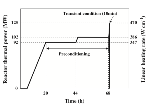
Figure 1: Power history for the B14 experiment (Maeda et al., 2011). The experiment consists in 48 hours of preconditioning at 102 MWt with a final transient of 10 minutes at 125 MWt.
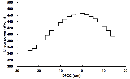
Figure 2: Axial power profile for the pin PTM003 over the position from the core mid plane (DFCC). Picture by courtesy of Takayuki Ozawa (JAEA) during a presentation at INL.
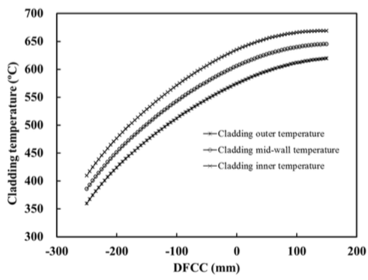
Figure 3: Axial cladding temperature profiles over the position from the core mid plane for the pins of the B14 experiment at 125 MWt. Picture by courtesy of Takayuki Ozawa (JAEA) during a presentation at INL.
Model Description
Geometry and Mesh
The fuel rod PTM003 was modeled as a smeared fuel pellet stack for the 2D RZ simulations. The geometric parameters specified in Table 1 were used to create the meshes for these simulations. The smeared fuel was meshed as a single smeared fuel column with 20 radial elements and 100 axial elements. For the 1D simulations meshes of 200 elements were used. Figure 4 shows a section of the mesh in 2D RZ with a temperature contour plot. This contour plot was made near the end of the run. Actual numbers are irrelevant in this case as this plot is only meant to show the discretization.
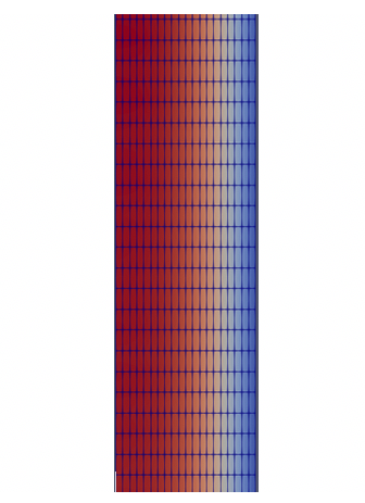
Figure 4: A section of the PTM003 fuel rod mesh with a temperature contour plot.
Input files
The BISON input and all supporting files (power histories, etc.) for this case are provided with the code distribution at bison/assessment/MOX/JOYO/B14/PTM003/analysis.
Material and Behavioral Models
The following material and behavioral models for MOX fuel were used:
FissionRateMOX: model that takes into account of the pore migration for the fission rate calculations
MOXPoreContinuity: pore migration, or restructuring, is modeled by applying the concept of pore conservation (Novascone et al., 2018).
MOXPoreDiffusion: pore migration, or restructuring, is modeled by applying the concept of pore conservation (Novascone et al., 2018).
MOXPoreVelocity: calculates pore speed according to (Sens, 1972) and (Novascone et al., 2018)
MAMOXThermal: model for temperature and porosity dependent thermal properties
ComputeFiniteStrainElasticStress: elastic mechanical behavior
MAMOXElasticityTensor: constant values from JAEA are used for the two elastic constants Young's modulus ( Pa) and Poisson ratio ()
MAMOXThermalExpansionEigenstrain: isotropic thermal expansion's eigenstrain from (Kato et al., 2011) and (Kato et al., 2016)
The following material and thermal behavior models were used for the cladding:
SS316Thermal: Thermophysical material properties
SS316ElasticityTensor: temperature-dependent Young's modulus and constant Poisson ratio ()
SS316ThermalExpansionEigenstrain: eigenstrain due to thermal expansion for Stainless Steel 316 using a function that describes the mean thermal expansion as a function of temperature
SS316CreepUpdate: steady state creep as sum of thermal and irradiation creep, following (Altenbach and Gorash, 2013) and (Garner and Porter, 1988)
Details and references for all of these models listed above can be found on the linked BISON documentation pages.
Results Comparison
Central void
The calculated central void size , (Novascone et al., 2018),for the fuel rod PTM003 is compared to the measured data in Figure 5, Figure 6 and Figure 7. There is also a comparison between 1D and a 2D simulations. The Multi-app was used in the 2D simulation order to have a better numerical solution in a point of view of convergences respect to a fully-coupled system. We assumed a value of 75% of porosity as threshold to consider a void and we delimited the end of the equiaxed region where the porosity equals the as-fabricated value.
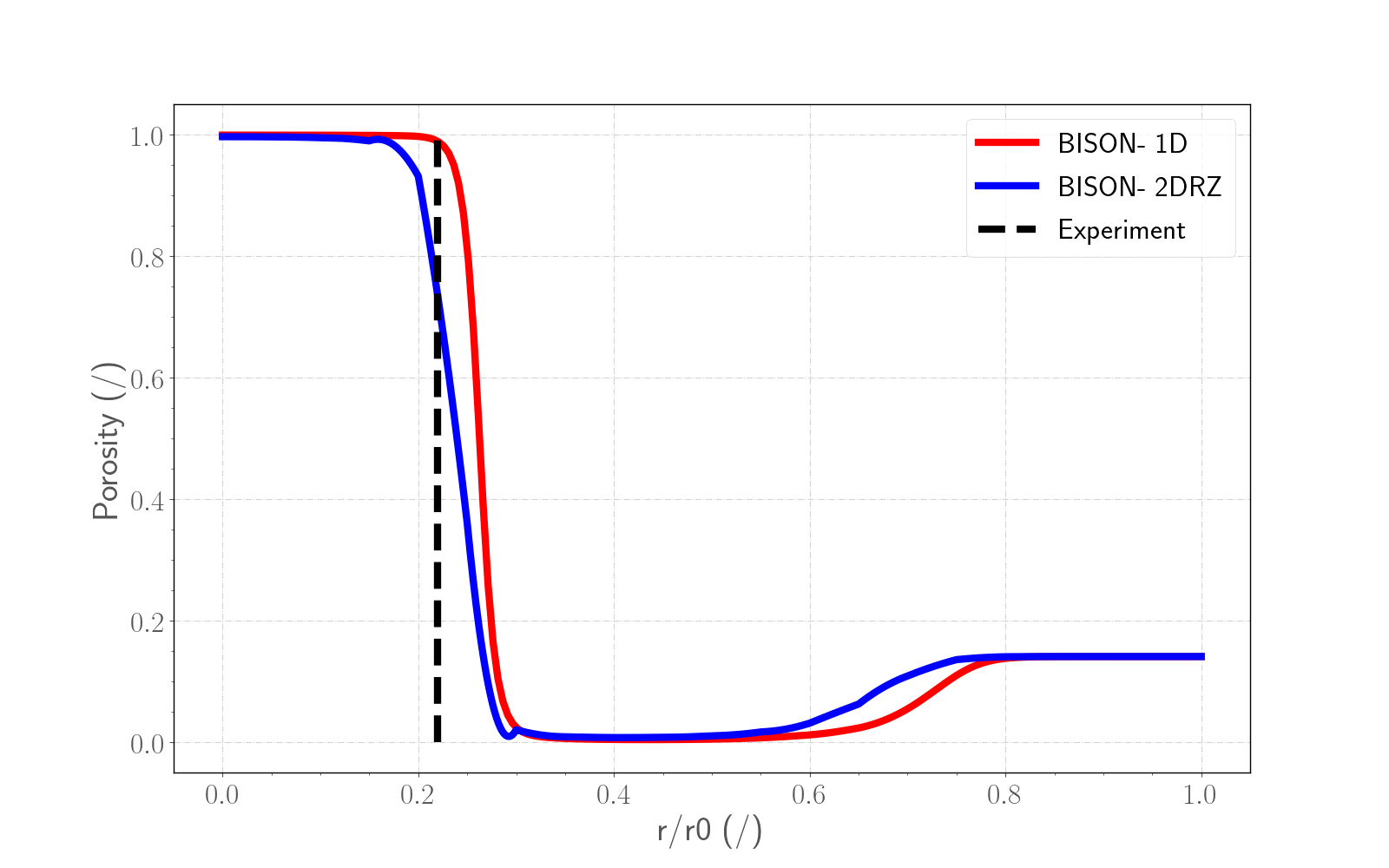
Figure 5: Comparison between the two simulations taken into account and the data for the sample 1 (+33 cm from the core mid plane). The Experimental dotted black line refers to the radius of the central void (Maeda et al., 2011).
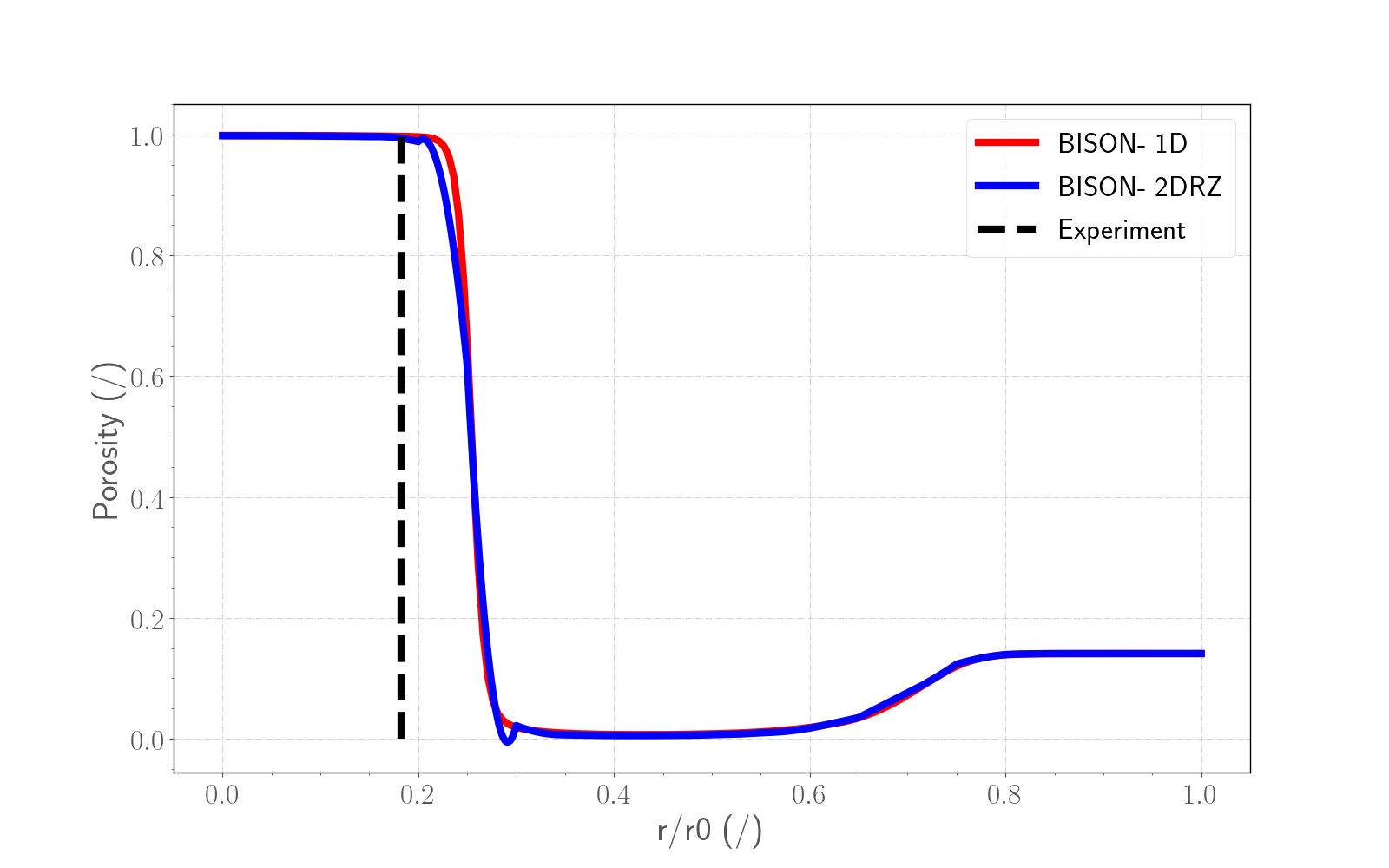
Figure 6: Comparison between the two simulations taken into account and the data for the sample 2 (+97 cm from the core mid plane). The Experimental dotted black line refers to the radius of the central void (Maeda et al., 2011).
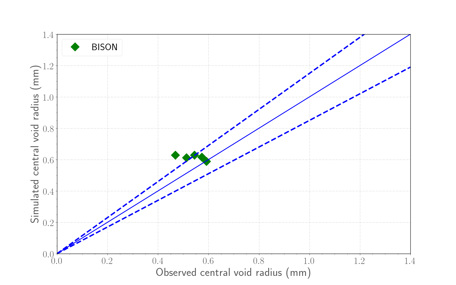
Figure 7: Comparison between the 2D simulation and the experimental data about the central void size for the fuel pin PTM003 in a range of (Maeda et al., 2011).
Discussion
The use of a Multi-App system with a fine mesh and many positions for the interpolation is recommended for the simulation of the central void.
References
- Holm Altenbach and Yevgen Gorash.
High-temperature inelastic behavior of the austenitic steel aisi type 316.
In Advanced Materials Modelling for Structures, pages 17–30.
Springer, 2013.[BibTeX]
- FA Garner and DL Porter.
Irradiation creep and swelling of aisi 316 to exposures of 130 dpa at 385-400 c.
Journal of Nuclear Materials, 155:1006–1013, 1988.[BibTeX]
- Yoshihisa Ikusawa, Koji Maeda, Masato Kato, and Masayoshi Uno.
Oxide-metal ratio dependence of central void formation of mixed oxide fuel irradiated in fast reactors.
Nuclear Technology, pages 83–95, 2017.[BibTeX]
- M. Kato, Y. c, T. Sunaoshi, A. Nelson, and K. McClellan.
Thermal expansion measurement of $(U,Pu)O_2-x$ in oxygen partial pressure-controlled atmosphere.
Journal of Nuclear Materials, 469:223–227, 2016.[BibTeX]
- M. Kato, K. Maeda, T. Ozawa, M. Kashimura, and Y. Kihara.
Physical properties and irradiation behavior analysis of Np- and Am-bearing MOX fuels.
Journal of Nuclear Science and Technology, 48:646–653, 2011.[BibTeX]
- K. Maeda, K. Katsuyama, Y. Ikusawa, and S. Maeda.
Short-term irradiation behavior of low-density americium-doped uranium-plutonium mixed oxide fuels irradiated in a fast reactor.
Journal of Nuclear Materials, 416(1-2):158–165, Sep 2011.[BibTeX]
- Stephen Novascone, Pavel Medvedev, John W. Peterson, Yongfeng Zhang, and Jason Hales.
Modeling porosity migration in lwr and fast reactor mox fuel using the finite element method.
Journal of Nuclear Materials, 508:226 – 236, 2018.[BibTeX]
- P.F. Sens.
The kinetics of pore movement in uo2 fuel rods.
Journal of Nuclear Materials, 43(3):293–307, 1972.
doi:10.1016/0022-3115(72)90061-X.[BibTeX]