FFTF FO-2 fuel pin L09
Overview
The FO-2 assembly has been irradiated in the Fast Flux Test Facility (FFTF), a sodium fast reactor, for 312 equivalent full power days (EFPD) (Gilpin et al., 1989). This test is one of the first that uses the alloy HT-9 as cladding material. The FO-2 assembly is composed by 169 fuel pins of twelve different types. The annular fuel pin L09 was destructively examined. This pin was punctured and it was cut at three different elevations (sample H, sample J and sample L).
Test Description
Rod Design Specifications
The fuel specifications from (Gilpin et al., 1989) and (Teague et al., 2014) for the L09 fuel pin are summarized in Table 1.
Table 1: FO-2 L09 fuel pin specifications.
| Fuel Rod | Measurement | Unit |
|---|---|---|
| Fuel stack height | 914 | mm |
| Nominal plenum height | 1057 | mm |
| Fill gas composition | He | |
| Fill gas pressure | 0.101325 | MPa |
| Fuel | Measurement | Unit |
| Material | MOX | |
| PuO content | 26.0 | |
| Smeared density | 80.0 | |
| Outer diameter | 5.59 | mm |
| Inner diameter | 1.397 | mm |
| Cladding | Measurement | Unit |
| Material | HT-9 | |
| Outer diameter | 6.858 | mm |
| Inner diameter | 5.792 | mm |
| Wall thickness | 0.533 | mm |
| Gap width | 101.6 | m |
Operating Conditions and Irradiation History
The base irradiation power history is shown in Figure 1. The coolant inlet temperature and pressure for the base irradiation is shown in Table 2.
Table 2: Operational input parameters.
| Measurement | Unit | |
|---|---|---|
| Coolant type | Sodium | |
| Coolant inlet temperature | 307 | C |
| Coolant pressure | 0.151 | MPa |
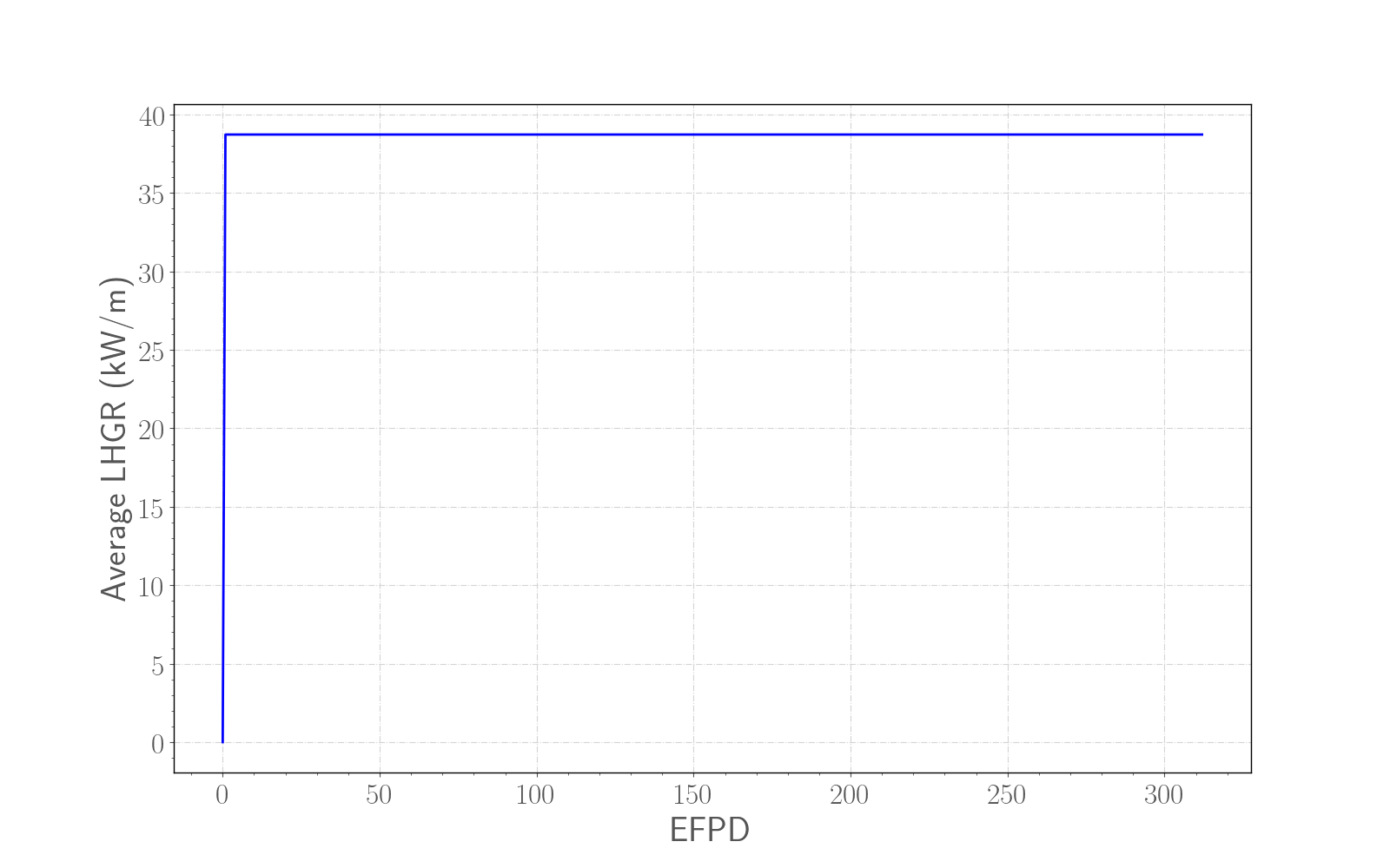
Figure 1: Base irradiation average power history for the fuel pin L09 of the FO-2 experiment (Teague et al., 2014).
Model Description
Geometry and Mesh
The fuel rod L09 was modeled as a smeared fuel pellet stack for the 2D RZ simulations. The geometric parameters specified in Table 1 were used to create the meshes for these simulations. The smeared fuel was meshed as a single smeared fuel column with 10 radial elements and 500 axial elements except for the calculation of the central void size. For the central void simulation was used a finer mesh with 30 radial elements and 500 axial elements. For the 1D simulations meshes of 1000 elements were used. Figure 2 shows a section of the mesh in 2D RZ with a temperature contour plot. This contour plot was made near the end of the run. Actual numbers are irrelevant in this case as this plot is only meant to show the discretization.
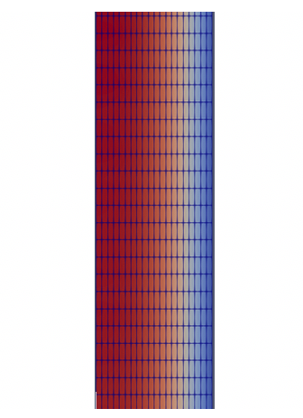
Figure 2: A section of the L09 fuel rod mesh with a temperature contour plot.
Input files
The BISON input and all supporting files (power histories, etc.) for this case are provided with the code distribution at bison/assessment/MOX/FFTF/FO-2/L09/analysis.
Material and Behavioral Models
The following material and behavioral models for MOX fuel were used:
FissionRateMOX: model that takes into account of the pore migration for the fission rate calculations
MOXPoreContinuity: pore migration, or restructuring, is modeled by applying the concept of pore conservation (Novascone et al., 2018).
MOXPoreDiffusion: pore migration, or restructuring, is modeled by applying the concept of pore conservation (Novascone et al., 2018).
MOXPoreVelocity: calculates pore speed according to (Sens, 1972) and (Novascone et al., 2018).
MAMOXThermal: model for temperature and porosity dependent thermal properties
ComputeFiniteStrainElasticStress: elastic mechanical behavior
MAMOXElasticityTensor: constant values from JAEA are used for the two elastic constants Young's modulus ( Pa) and Poisson ratio ()
MAMOXThermalExpansionEigenstrain: isotropic thermal expansion's eigenstrain from (Kato et al., 2011) and (Kato et al., 2016)
UO2VolumetricSwellingEigenstrain: volumetric expansion due to solid and gaseous swelling
UO2Sifgrs: fission gas release model used with the gaseous swelling model UO2VolumetricSwellingEigenstrain (Pastore et al., 2015)
The following material and thermal behavior models were used for the cladding:
HT9Thermal: computes thermal properties of HT-9 martensitic steel
ComputeIsotropicElasticityTensor: constant values are used for the two elastic constants Young's modulus ( Pa) and Poisson ratio ()
ComputeThermalExpansionEigenstrain: constant values are used for the thermal expansion coefficient ( )
HT9CreepUpdate: steady state creep as sum of thermal and irradiation creep
Details and references for all of these models listed above can be found on the linked BISON documentation pages.
Results Comparison
Central void
The calculated central void size , (Novascone et al., 2018),for the fuel rod L09 is compared to the measured data in Figure 3, Figure 5 and Figure 7. There is also a comparison between 1D, 2D coarse mesh with just 3 positions for the Multi-App Interpolation and 2D fine mesh with 30 positions for the Multi-App Interpolation simulations. The Multi-app was used in order to have a better numerical solution in a point of view of convergences respect to a fully-coupled system. Since with a 2D coarse mesh and just 3 positions Multi-App simulation (yellow line Figure 3 and Figure 5) there is a negative value of porosity, we decided to refine the mesh and add more positions to the Multi-App Interpolation in order to fix that not physical porosity value (purple line Figure 3 and Figure 5). We assumed a value of 50% of porosity as threshold to consider a void and we delimited the end of the equiaxed region where the porosity equals the as-fabricated value.
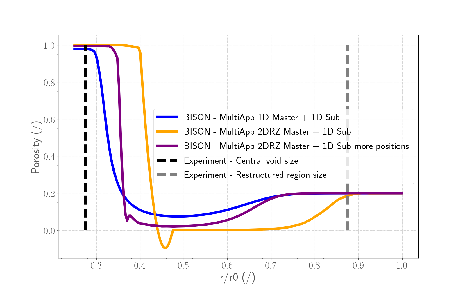
Figure 3: Comparison between the three simulations taken into account and the data for the sample H (43.2 cm from the fuel bottom). The Experimental dotted black line refers to the radius of the central void and the gray one refers to the restructured region size (Gilpin et al., 1989). Every curve begins from the inner radius of the annular fuel.
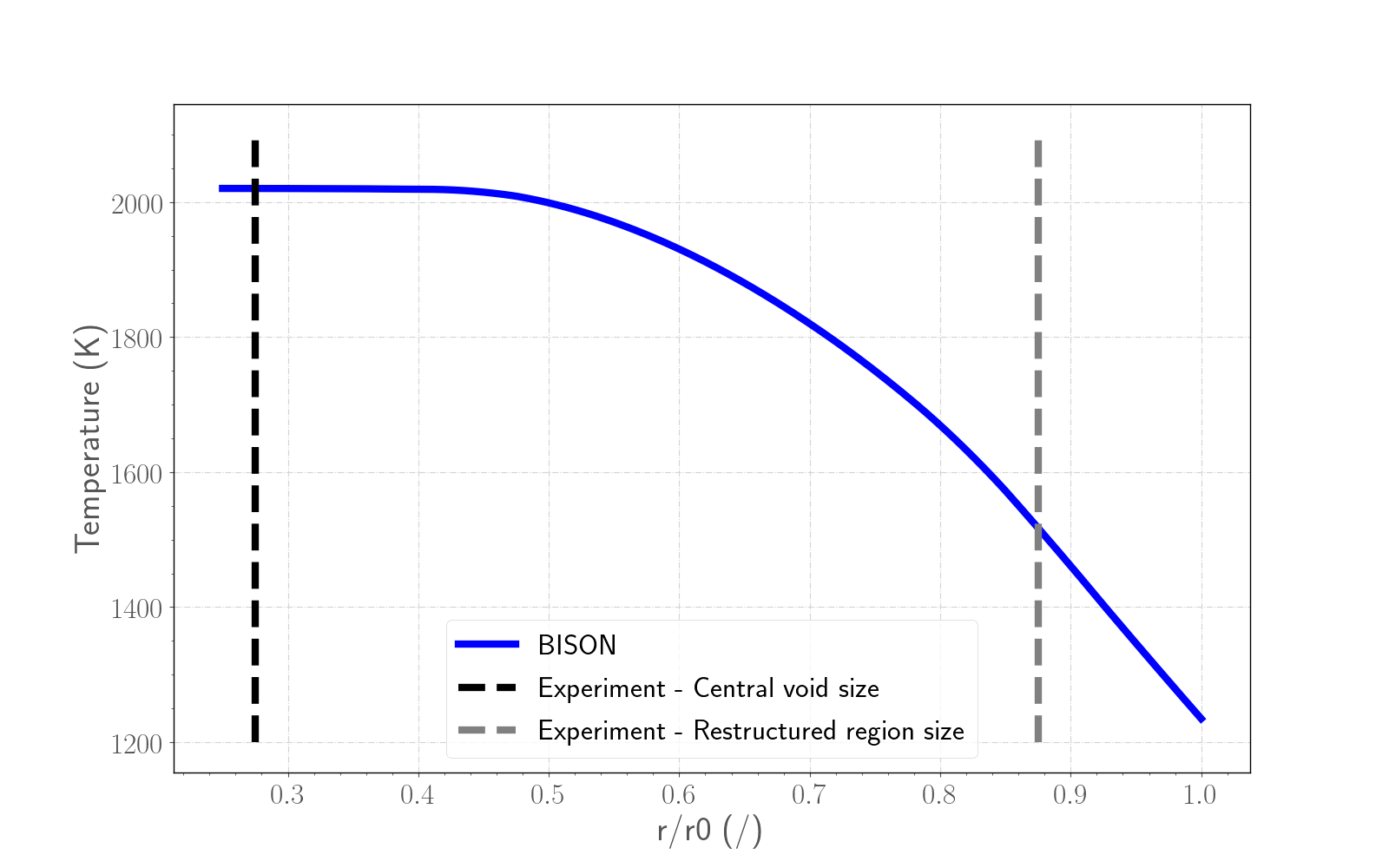
Figure 4: Temperature calculated with the 2D fine mesh Multi-App Interpolation simulation for the sample H (43.2 cm from the fuel bottom). The Experimental dotted black line refers to the radius of the central void and the gray one refers to the restructured region size (Gilpin et al., 1989). The curve begins from the inner radius of the annular fuel.
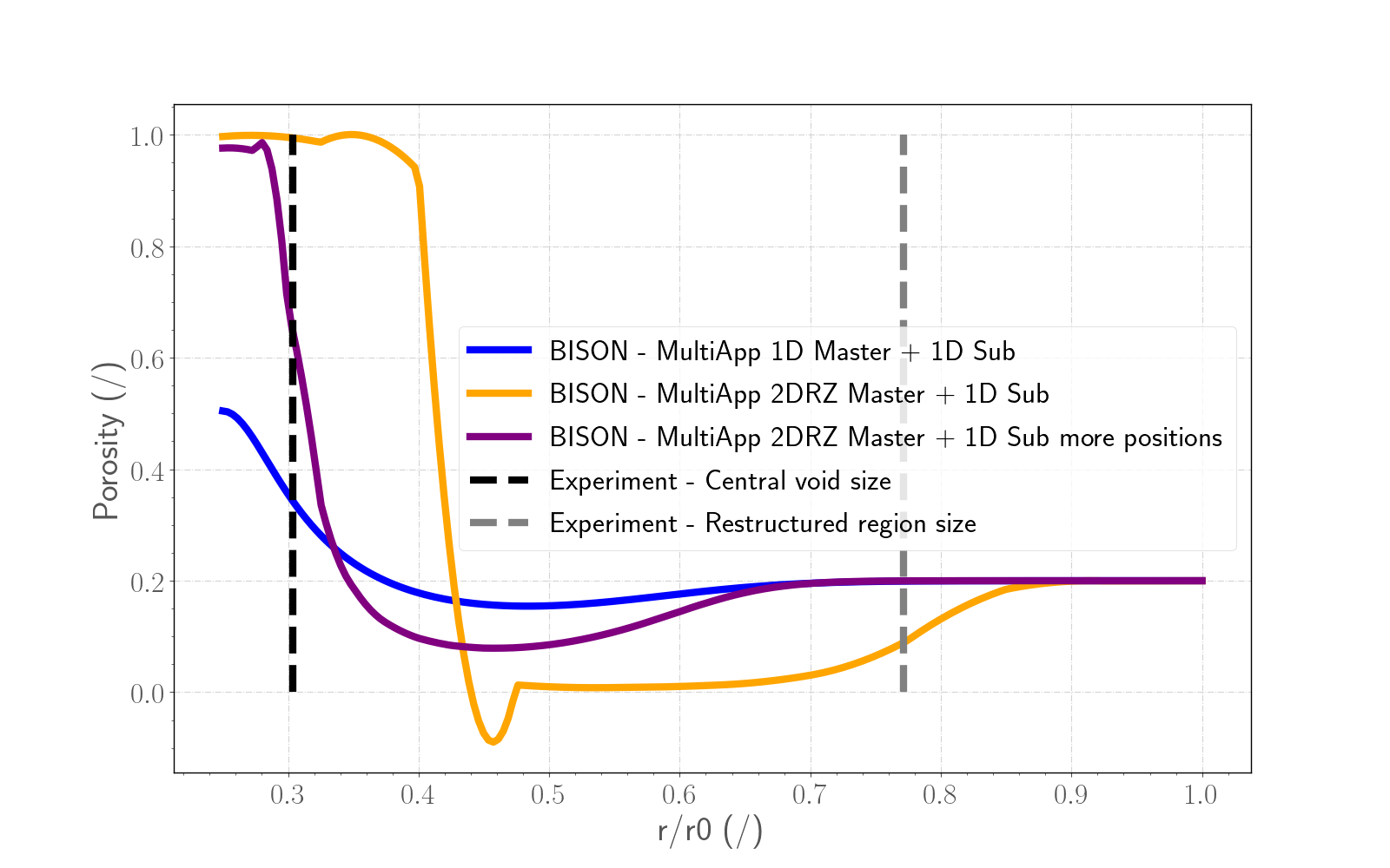
Figure 5: Comparison between the three simulations taken into account and the data for the sample J (68.6 cm from the fuel bottom). The Experimental dotted black line refers to the radius of the central void and the gray one refers to the restructured region size (Gilpin et al., 1989). Every curve begins from the inner radius of the annular fuel.
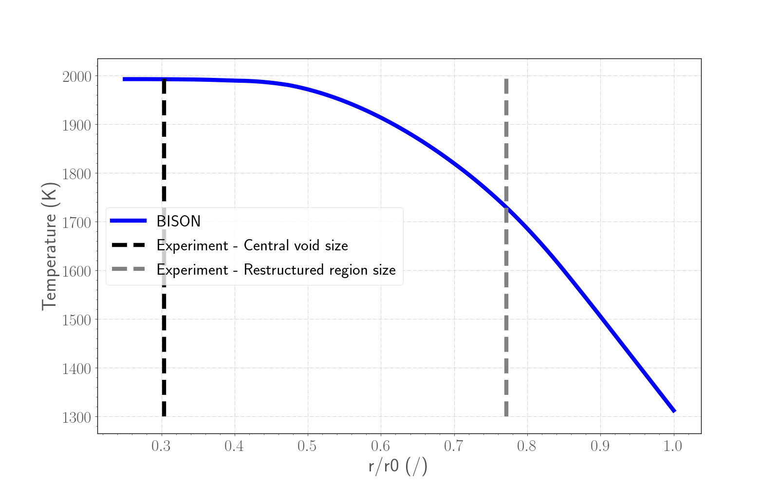
Figure 6: Temperature calculated with the 2D fine mesh Multi-App Interpolation simulation for the sample J (68.6 cm from the fuel bottom). The Experimental dotted black line refers to the radius of the central void and the gray one refers to the restructured region size (Gilpin et al., 1989). The curve begins from the inner radius of the annular fuel.
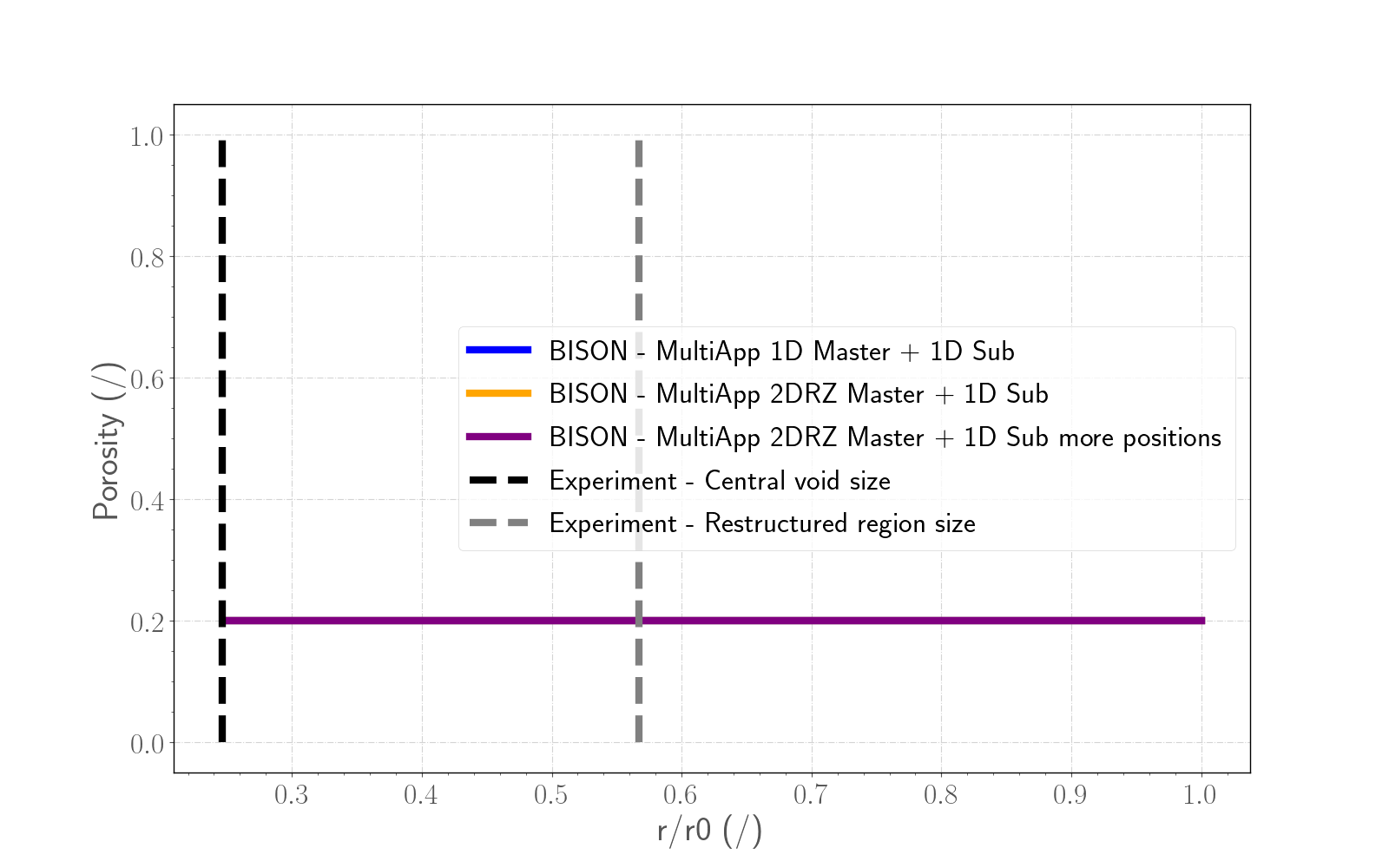
Figure 7: Comparison between the three simulations taken into account and the data for the sample L (91.3 cm from the fuel bottom). The Experimental dotted black line refers to the radius of the central void and the gray one refers to the restructured region size (Gilpin et al., 1989). Every curve begins from the inner radius of the annular fuel.
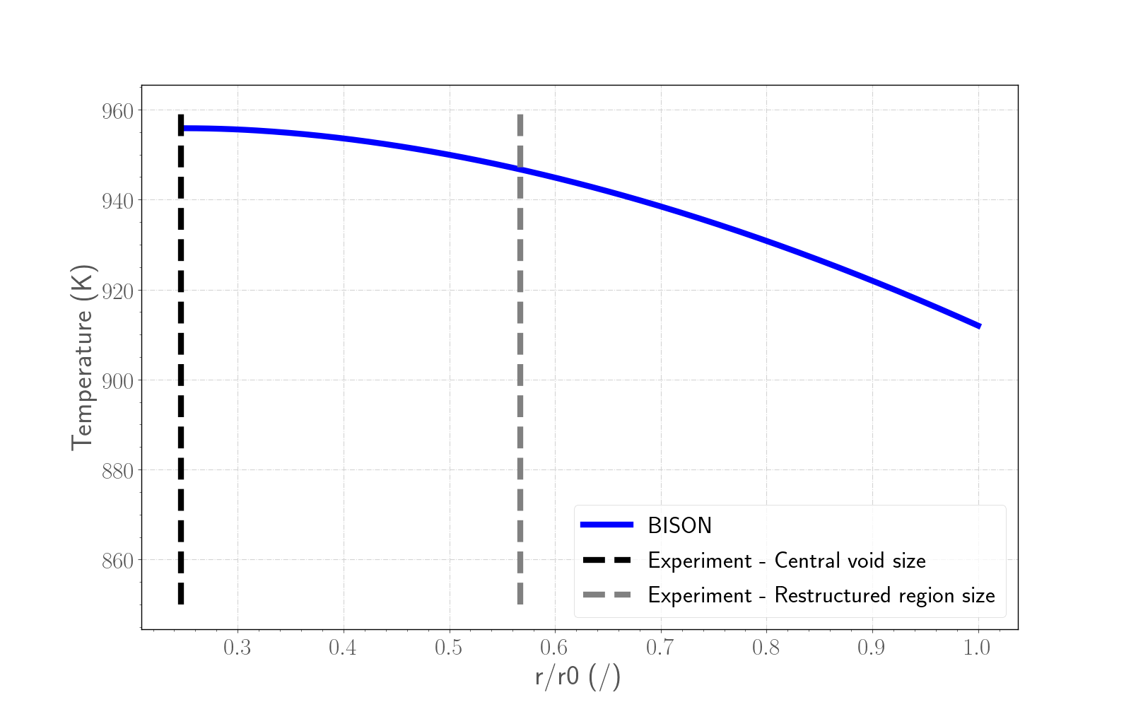
Figure 8: Temperature calculated with the 2D fine mesh Multi-App Interpolation simulation for the sample L (91.3 cm from the fuel bottom). The Experimental dotted black line refers to the radius of the central void and the gray one refers to the restructured region size (Gilpin et al., 1989). The curve begins from the inner radius of the annular fuel.
Fission Gas Release
The calculated integral fuel rod FGR is compared to the measured data in Figure 9 . BISON results with the recommended lower limit for the number density of grain boundary bubbles (10 bubbles/m) for FBR MOX fuels show a good agreement with the experimental data, in line with the intrinsic modeling uncertainties (Pastore et al., 2014).
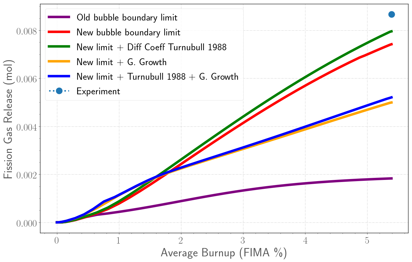
Figure 9: Fission gas release comparison. The purple line refers to the basic case with the current lower limit for the bubble number density at the grain boundary of 10 bubbles/m; the red one refers to the new basic case with the new lower limit for the bubble number density at the grain boundary of 10 bubbles/m; the green line corresponds to the new basic case that uses the diffusion coefficient for fission gasses proposed in (Turnbull et al., 1988); the yellow one corresponds to the new basic case with the grain growth model turned on (Ainscough et al., 1973); the blue curve refers to the new basic case with the diffusion coefficient for fission gasses proposed in (Turnbull et al., 1988) and with the grain growth model turned on.
Discussion
The use of a Multi-App system with a fine mesh and many positions for the interpolation is recommended for the simulation of the central void.
For fast MOX fuels, higher temperatures are reached compared to LWR fuels. The associated pronounced bubble growth and coalescence can lead to the attainment of the lower limit for the number density of grain boundary bubbles systematically. Preliminary simulations of FBR MOX irradiations have indicated that a value of leads to a more accurate result in terms of both FGR and swelling compared to the default LWR UO value. A value of is compatible with experimental observations, e.g., (White, 2004).
References
- J.B. Ainscough, B.W. Oldfield, and J.O. Ware.
Isothermal grain growth kinetics in sintered UO$_2$ pellets.
Journal of Nuclear Materials, 49:117–128, 1973.[BibTeX]
- L.L. Gilpin, R.B. Baker, and S.A Chastain.
Evaluation of the advanced mixed oxide fuel test fo-2 irradiated in fast flux test facility.
Technical Report, Westinghouse Hanford Co., Richland, WA (USA), May 1989.[BibTeX]
- M. Kato, Y. c, T. Sunaoshi, A. Nelson, and K. McClellan.
Thermal expansion measurement of $(U,Pu)O_2-x$ in oxygen partial pressure-controlled atmosphere.
Journal of Nuclear Materials, 469:223–227, 2016.[BibTeX]
- M. Kato, K. Maeda, T. Ozawa, M. Kashimura, and Y. Kihara.
Physical properties and irradiation behavior analysis of Np- and Am-bearing MOX fuels.
Journal of Nuclear Science and Technology, 48:646–653, 2011.[BibTeX]
- Stephen Novascone, Pavel Medvedev, John W. Peterson, Yongfeng Zhang, and Jason Hales.
Modeling porosity migration in lwr and fast reactor mox fuel using the finite element method.
Journal of Nuclear Materials, 508:226 – 236, 2018.[BibTeX]
- G. Pastore, D. Pizzocri, S. R. Novascone, D. M. Perez, B. W. Spencer, R.L. Williamson, P. Van Uffelen, and L. Luzzi.
Modelling of transient fission gas behaviour in oxide fuel and application to the BISON code.
In Enlarged Halden Programme Group Meeting, Røros, Norway, September 7-12, volume. 2014.[BibTeX]
- G. Pastore, L.P. Swiler, J.D. Hales, S.R. Novascone, D.M. Perez, B.W. Spencer, L. Luzzi, P. Van Uffelen, and R.L. Williamson.
Uncertainty and sensitivity analysis of fission gas behavior in engineering-scale fuel modeling.
Journal of Nuclear Materials, 465:398–408, 2015.[BibTeX]
- P.F. Sens.
The kinetics of pore movement in uo2 fuel rods.
Journal of Nuclear Materials, 43(3):293–307, 1972.
doi:10.1016/0022-3115(72)90061-X.[BibTeX]
- Melissa Teague, Michael Tonks, and Stephen Novascone.
Microstructural modeling of thermal conductivity of high burn-up mixed oxide fuel.
Journal of Nuclear Materials, 444(1):161 – 169, 2014.[BibTeX]
- J. A. Turnbull, R.J. White, and C. Wise.
The diffusion coefficient for fission gas atoms in uranium dioxide.
In Proceedings of Technical Committee Meeting on Water Reactor Fuel Element Computer Modelling in Steady State, Transient and Accident Conditions, 174–181. Preston, UK, Sept. 18-22, 1988.[BibTeX]
- R.J. White.
The development of grain-face porosity in irradiated oxide fuel.
Journal of Nuclear Materials, 325:61–77, 2004.[BibTeX]