RIA NSRR FK Tests
Overview
NSRR is a modified TRIGA (Training, Research, Isotopes, General Atomics) ACPR (Annular Core Pulse Reactor) with a dry space located in the center of the core. In a simulated RIA test for an irradiated fuel, a single instrumented fuel rod in a water-filled capsule is placed in the center of the core, and is pulse irradiated.
A large number of experiments on simulated RIA have been performed at the test facility of NSRR to evaluate the fuel rod behavior and failures at different energy depostion, burnup, fuel design, and coolant condition. Since 1989, tests on medium and high burnup fuels in NSRR have been started and continued; recent experiments moved towards the testing on high burnup fuel with advanced corrosion resistant cladding alloys such as MDA and Zirlo (Amaya et al., 2014). Pulse irradiation tests were normally performed in stagnant coolant water at room temperature (20C) and atmospheric pressure (0.1 MPa) under a narrow power pulse with Full Width at Half Maximum (FWHM) of approximately 5 ms. Recent tests were performed at high coolant temperature (280C) and high pressure (up to 6.4 MPa) to provide measurements on fuel failures at conditions close to Hot Zero Power (HZP) condition. The current evaluation was performed on early RIA tests conducted at room temperature and atmospheric pressures; a number of tests on BWR type fuels with burnup from 41 to 61 GWd/tU (three and four cycles) were selected for the validation of BISON code based on published information from JAEA (formerly known as JAERI) (Nakamura et al., 2002) (Nakamura et al., 2000).
BISON time domain results on this page have not been updated to reflect the latest modeling and simulation formulations.
Test Description
Rod Design Specifications
An overview of NSRR FK cases selected for BISON assessment is shown in Table 1. All the fuel types are UO fuel enriched to 4.5% with zirconium-lined recrystallized Zircaloy-2 cladding, and were refabricated into short rodlets to fit into the NSRR test capsule. All the test rods selected for evaluations are short rodlets with an active fuel stack length of 102 mm (10 pellets) or 128 mm (12 pellets).
Table 1: Overview of NSRR FK cases
| Test | FK1 | FK2 | FK3 | FK4 | FK5 | FK6 | FK7 | FK8 | FK9 |
|---|---|---|---|---|---|---|---|---|---|
| Clad thickness (mm) | 0.86 | 0.86 | 0.86 | 0.86 | 0.86 | 0.86 | 0.86 | 0.86 | 0.86 |
| Fuel density (%TD) | 0.97 | 0.97 | 0.97 | 0.97 | 0.97 | 0.97 | 0.97 | 0.97 | 0.97 |
| U235 enrichment (%) | 4.5 | 4.5 | 4.5 | 4.5 | 4.5 | 4.5 | 4.5 | 4.5 | 4.5 |
| Burnup (GWd/tU) | 45 | 45 | 41 | 56 | 56 | 61 | 61 | 61 | 61 |
| Fill gas pressure (MPa) | 0.3 | 0.3 | 0.3 | 0.5 | 0.5 | 0.1 | 1.5 | 1.5 | 1.5 |
| Energy deposit (cal/g) | 167 | 95 | 186 | 180 | 100 | 168 | 166 | 90 | 119 |
| Peak fuel enthalpy (cal/g) | 129.52 | 69.8 | 144.5 | 139.5 | 69.8 | 130.5 | 128.6 | 64.8 | 89.8 |
| Power Pulse width (ms) | 4.5 | 7 | 4.5 | 4.3 | 7.3 | 4.3 | 4.3 | 7.3 | 5.7 |
| Failure enthalpy (cal/g) | - | - | - | - | - | 70 | 62 | - | 86 |
Operating Conditions and Irradiation History
Fuel rod segements for Tests FK-1, FK-2, and FK-3 were irradiated in Fukushima Daiichi Unit 3 for three cycles to a burnup level of 41 to 45 GWd/tU, and FK-4 - FK-9 were irradiated in Fukushima Daini Unit 2 to a burnup level of 56 to 61 GWd/tU (Nakamura et al., 2002) (Nakamura et al., 2000). The short fuel segment for each rod has a flat axial burnup profile from base irradiation, and a uniform axial power profile in the RIA transient.
Those rodlets were tested in NSRR reactor at room temeprature (20C) and atmospheric pressure (0.1 MPa) condition with stagnant flow.

Figure 1: Finite Element Grid for the BISON Analyses of the NSRR RIA Tests
Model Description
Geometry and Mesh
The rod specifications and geometry in Table 1 and were used to define the geometry for the cases. The 9 cases were modeled using a two-dimensional, axisymmetric (2D-RZ) mesh with eight-node quadratic elements.
The mesh consists of 16 radial elements with 12 in the fuel and 4 in the cladding. 100 axial elements were used for modeling in the axial direction. A typical finite element grid for the RIA tests is illustrated in Figure 1.
Material and Behavioral Models
The material and behavior model options used for modeling the RIA test cases are listed below:
Fuel thermal conductivity: NFIR thermal conductivity model is used
Fuel mechanical models: elastic fuel is assumed for the modeling
Fission gas release and swelling: fission gas release and swelling models are turned off
Thermal model of clad: MATPRO model on thermal conductivity and specific heat for Zircaloy is used (ThermalZry)
Clad mechanical model: plastic deformation model of Zircaloy (ZryPlasticity) is used
Boundary and Operating Conditions
The thermal and mechanical boundary condtions used for the test cases are described as follows:
Mechanical contact model: frictionless model is used
Thermal contact model: GasGapHeatTransfer thermal contact model is used
Thermal boundary condition: clad temperature is specified for all test cases; one example of using coolant channel model is provided for modeling DNB for test case FK-3
The power history during the simulated RIAs for the test cases are plotted in Figure 2.

Figure 2: Power Pulses for the NSRR BWR RIA Tests.
Base irradiation simulation was performed for the BWR rods with the design geometry and material of the test rods to provide the parameters of gap size and fast neutron fluence for modeling the RIA transients. Radial power and burnup profiles at the end of base irradiation were taken from (Nakamura et al., 2000) for preparing the pre-transient conditions.
Since the RIA test cases were prepared based on conditions after base irradiation, the variables describing the as-irradiated conditions such as burnup, fast neutron fluence, gap size, and radial power rofiles are inputs in those test cases. However, fission gas inventory at fuel grain boundaries can not be easily established using such methodology; therefore fission gas release and swelling were not modeled in those test cases. It would be of interest to develop a simple model in BISON to compute the pre-transient fission gas inventory for predicting the fission gas release in a fast transient in the future.
The coolant channel model was tested for the modeling of DNB in a RIA for one selected test case FK-3.
Input files
The BISON input and all supporting files (power histories, axial power profile, fast neutron flux history, etc.) for NSRR FK cases are provided with the code distribution at bison/assessment/LWR/validation/RIA_NSRR_FK/analysis.
Results
This section describes results of the evaluation of NSRR RIA tests using BISON code. Results of temprature predictions on NSRR FK cases calculated by BISON along with Falcon predictions are summarized in Figure 5 and Figure 6. Results of clad hoop strains calcuated by BISON is shown in Table 3 in comparison to Falcon results (Liu et al., 2010).
Figure 3 provides the radial temperature profiles for FK-1 - FK-9 at the time of peak rim temperature. Figure 4 provides the radial temperature profiles for FK-1 - FK-9 at the time of peak fuel centerline temperature.
Those results have shown the typical thermal response during a RIA; the pellet has an initial edge-peaked profile, and then decreases rapidly while the fuel centerline features a more gradual temperature reduction. This is futher illustrated in the example of case FK3 in Figure 5 which provides calculated temperature at fuel centerline, fuel outer surface, and clad inner surface.
Table 2: Summary of Fuel Temperatures of the FK cases
| Case | Peak Clad Inner Surface Temp | Peak Rim Temp by Falcon (C) (Montgomery and Sunderland, 2003) | Peak Centerline Temp by Falcon | Peak Rim Temp (C) | Peak Centerline Temp (C) |
|---|---|---|---|---|---|
| FK-1 | 645 | 2529 | 1569 | 2353 | 1583 |
| FK-2 | 386 | 1360 | 880 | 1390 | 902 |
| FK-3 | 678 | 2691 | 1737 | 2574 | 1723 |
| FK-4 | 730 | 2747 | 1591 | 2616 | 1652 |
| FK-5 | 407 | 1290 | 852 | 1450 | 884 |
| FK-6 | 509 | 2696 | 1510 | 2723 | 1521 |
| FK-7 | 503 | 2648 | 1509 | 2699 | 1501 |
| FK-8 | 274 | 1339 | 788 | 1595 | 804 |
| FK-9 | 367 | 2007 | 1146 | 2122 | 1082 |
Table 3: Summary of Clad Hoop Strains of FK cases
| Case | H H (cal/g) | Peak SED or SED at failure (MJ/m) | Calculated Falcon Peak Hoop Strain by (%) (Liu et al., 2010) | Calculated Peak Hoop Strain (%) | Measured Residual Strain (%) | Calculated Residual Hoop Strain (%) |
|---|---|---|---|---|---|---|
| FK-1 | 130 | 4.25 | 1.30 | 0.84 | 0.85 | 0.22 |
| FK-2 | 70 | 2.28 | 0.4 | 0.65 | 0 | 0.00 |
| FK-3 | 145 | 4.11 | 1.55 | 0.84 | 1.47 | 0.18 |
| FK-4 | 140 | 4.14 | 1.75 | 0.84 | 1.25 | 0.17 |
| FK-5 | 70 | 2.35 | 0.41 | 0.65 | 0 | 0.00 |
| FK-6 | 70 131 | 4.03 | 1.7 | 0.84 | Failed | 0.18 |
| FK-7 | 62 129 | 3.98 | 1.6 | 0.84 | Failed | 0.18 |
| FK-8 | 65 | 2.04 | 0.6 | 0.62 | 0 | 0.00 |
| FK-9 | 86 90 | 3.70 | 1.0 | 0.84 | Failed | 0.05 |
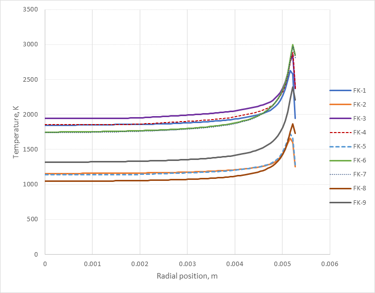
Figure 3: Radial Fuel Temperature Profiles for the FK 1-9 Fuel Rods at the Time and Elevation of Peak Fuel Temperature in the Rim Region
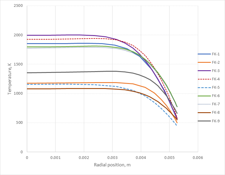
Figure 4: Radial Fuel Temperature Profiles for the FK 1-9 Fuel Rods at the Time and Elevation of Peak Fuel Ceneterline Temperature
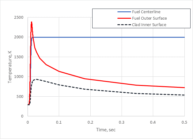
Figure 5: FK3 Temp Version 1
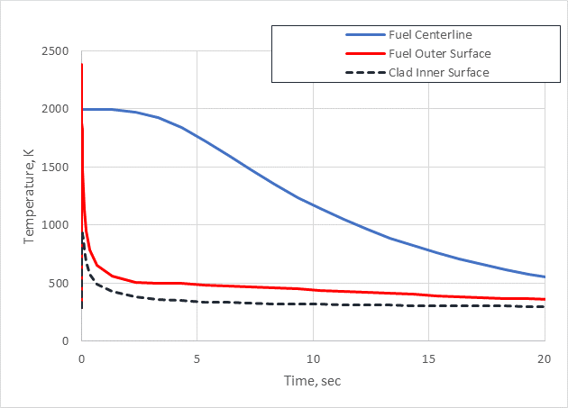
Figure 6: FK3 Temp Version 2
Discussion
BISON calculations on the fuel temperatures matches closely to Falcon results for most cases, except for a few cases on peak rim temperature predictions. Using same power history as Falcon code, the calculated enthaly by BISON in general is higher than the reported value from experiments, with a maximum over-prediction of 10%.
Clad permanent hoop strains calculated by BISON are smaller than measurements and Falcon code results. This could be caused by the gap size used for the pre-transient conditions from BISON calculations at the end of base irradiation, which is larger than the gap size assumed in Falcon analysis.
The current thermal boundary condtion uses specified cladding temperature which is same as the one used in (Montgomery and Sunderland, 2003), and this is considered to be adequate to predict the Pellet Clad Mechanical Interaction (PCMI) phase in the RIA since cladding outer surface temeprature changes little during the power pulse. In some tests (FK-1, FK-3, FK-4, and FK-9), cladding temperature escalation was observed after the power pulse phase, which was considered to be caused by the Departure from Nucleate Boiling (DNB). The coolant channel model was tested for the modeling of DNB in a RIA for case FK-3, it was found that the model under-predict the CHF , which empirically scales the Zuber correlation to match the measured CHF from transient pool boiling tests (Bessiron, 2007). By lowering the scaling factor to force the DNB to occur, the current coolant model tends to over-predict the clad temperature. The reason could be the lack of the considerations of the radiation heat transfer in the film boiling phase or the under-prediction of the rewetting temperature. Further model and code changes would be needed to improve the prediction of cladding temperature during DNBs.
Frictional model was tested but failed to converge, and therefore a frictionless model was used instead, and for this reason, no comparison to measurements on the axial fuel elongation was performed.
Conclusion
Simulated RIA tests on irradiateiond BWR rods FK-1 - FK-9 were modeled using BISON code. BISON calculations results were compared to measurements and Falcon code results. A few observations can be made with regard to the current validation:
BISON tends to over-predict the peak fuel enthalpy in comparison to Falcon code.
BISON agrees well with Falcon on the temperature predictions, and could capture the characteristics of the temperature profile during a pulse irradiation.
BISON tends to under-predict the clad permanent hoop strain as compared to Falcon code and experiements; this could be caused the relatively larger pre-transient gap size used in the BISON calculations.
The clad permanent axial strain is also under-predicted, which can be attributed to the pre-transient gap size as well as the lack of frictional contact in modeling those test cases.
BISON tends to under-predict the CHF compared to the measured CHF in pool boling tests (Bessiron, 2007);
Current results indicate some input, such as gap size and rod power, of those test cases might need to be refined, and further code improvements, e.g. the contact model and the coolant channel model, would be needed to augment the capability for the applications to modeling RIA transients.
References
- Masaki Amaya, Fumihisa Nagase, Tomoyuki Sugiyama, Yutaka Udagawa, Takafumi Narukawa, and Akihiko Sawada.
Current Studies at JAEA on Fuel Behaviors under Accident Conditions.
In Proceedings of WRFPM 2014. Sendai, Japan, September 14-17 2014.[BibTeX]
- V. Bessiron.
Modeling of clad-to-coolant heat transfer for ria applications.
Journal of Nuclear Science and Technology, 44(2):211–221, 2007.[BibTeX]
- Wenfeng Liu, John Alvis, Robert Montgomery, and Ken Yueh.
Analysis of High Burnup Fuel Failures at Low Temperatures in RIA Tests Using CSED.
In Proceedings of 2010 LWR Fuel Performance. Orlando, Florida, USA, Sepember 26-29 2010.[BibTeX]
- R. Montgomery and D. Sunderland.
Analysis of reactivity initiated accident-simulation tests conducted at the CABRI and NSRR facilities in france and japan.
Technical Report 1002863, Electric Power Research Institute, December 2003.[BibTeX]
- T. Nakamura, K. Kusagaya, T. Fuketa, and H. Uetsuka.
High-burnup BWR Fuel Behavior under Simulated Reactivity-initiated Accident Conditions.
Nuclear Technology, 138(3):246–259, 2002.[BibTeX]
- T. Nakamura, M. Yoshinaga, M. Takahashi, K. Okonogi, and K. Ishijima.
Boiling Water Reactor Fuel Behavior under Reactivity-initiated-accident Conditions at Burnup of 41 to 45 GWd/tonne U.
Nuclear Technology, 129(2):141–151, 2000.[BibTeX]
- Takehiko Nakamura, Masato Takahashi, and Makio Yoshinaga.
Evaluation of burnup characteristics and energy deposition during nsrr pulse irradiation tests on irradiated bwr fuels.
Technical Report JAERI-Research 2000-048, JAERI, September 2000.[BibTeX]