RIA CABRI REP Na-4
Overview
The RIA tests at the CABRI reactor facility began in 1992 by the Institut de Protection et de Sûreté Nucléaire" (IPSN which is now IRSN) in collaboration with Electricité de France (EDF), Framatome, CEA, and with participation of the US NRC. A total of twelve tests were performed within the CABRI REP sodium loop using preirradiated fuel rods having burnups ranging between 33 and 65 GWd/tU. Of the twelve, eight contained UO2 fuel and four were MOX. The cladding for all tests was Zircaloy 4 except test 11 which was M5. Following the CABRI REP program, another series of tests have been initiated under the CABRI International Program (CIP) to test high burnup fuel with advanced cladding alloys.
The CABRI test reactor is a pool-type Light Water Reactor (LWR) designed with a central area that can accept the insertion of a test device. The central area was originally designed to study fast reactor transients and contains a sodium coolant loop. During the experiment, the test rod is placed inside a test capsule which contains the in-pile instrumentation. Due to the sodium coolant loop, the test capsule temperature and pressure are different from LWR conditions, but the tests are considered appropriate to study the response of the rodlet up to the departure from nucleate boiling point. Under these conditions the effects of pellet cladding mechanical interaction (PCMI) can be tested.
The test chosen for evaluation in this study is the CABRI REP Na-4 case with UO2 fuel and Zircaloy-4 cladding. It will be discussed in detail in the following section. Details of the modelling options will then be discussed followed by a comparison of the results.
Test Description
An overview of the CABR REP Na-4 test is shown in Table 1. The REP Na-4 rodlet was obtained from rod EDF1065 which was irradiated in Gravelines for 5 cycles to a rod average burnup of 62 GWd/tU. The test rod was refabricated from a fuel segment removed from the 5th span. The rodlet fuel length was 563 mm and an almost uniform oxide thickness of 80 µm over the length of the rodlet. The FABRICE method was used to refabricate the rod and refill the plenum to 0.301 MPa. The local average burnup of the REP Na-4 sample was 64 GWd/tU.
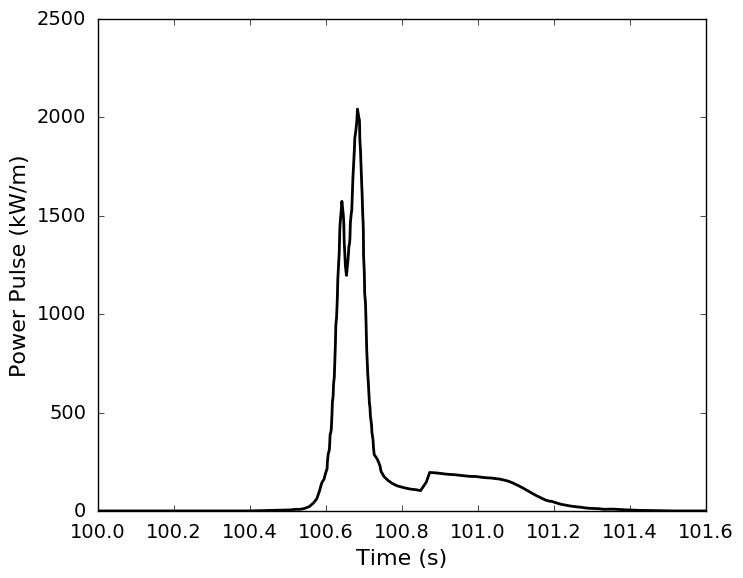
Figure 1: CABRI REP Na-4 power pulse
The rod was tested with a FWHM pulse width of 76.4 ms and depositing 397 J/g (95 cal/g) of energy into the fuel 1.2 seconds after the initiation of the transient. The REP Na-4 test was designed to use a wide power pulse to represent the expected conditions during an RIA event in an LWR. The wider pulse was accomplished by modifying the reactivity control system in CABRI to produce two separate reactivity insertions generating two overlapping power pulses to produce a single wide pulse. The power history is shown in Figure 1 where the two power pulses are clearly evident. The effective full-width-at-half-maximum (FWHM) of the pulse is estimated at 76.4 ms. At the end of the pulse and additional power step was introduced at 0.86 seconds after the initial pulse initiation. The total energy deposition for this case was determined by the CABRI facility to be 95 cal/g at 1.2 seconds after the initiation of the transient. It should be noted that in the BISON simulation the problem was initialized to hot-zero power (HZP) conditions during the first 100 seconds and the RIA transient begins at 100 seconds.
Table 1: CABRI REP Na-4 case overview
| Test | REP Na-4 |
|---|---|
| Fuel Type | 17x17 UO |
| Cladding Type | Std Zy-4 |
| Initial enrichment (U/U %) | 4.5 |
| Internal gas pressure (MPa, 20C) | 0.301 |
| Active fuel length (mm) | 563 |
| Max. burnup (GWd/tU) | 62 |
| Corrosion thickness (m) | 60-80 |
| Pulse width FWHM (ms) | 76.4 |
| Energy deposit (cal/g) J/g | 95 397.5 |
| Cladding OD (mm) | 9.51 |
| Cladding thickness (mm) | 0.578 |
| Pellet OD (mm) | 8.19 |
| Pellet height (mm) | 13.74 |
| Diametral fuel-cladding gap (m) | 164 |
| Coolant type | Sodium |
| Coolant pressure (MPa) | 0.5 |
| Coolant Temp. (C) | 280 |
Model Description
Geometry and Mesh
Table 2: Summary of BISON input models and parameters
| Model | Parameters |
|---|---|
| Fuel thermal conductivity | NFIR |
| Fuel mechanical model | Elastic model with temperature dependent properties |
| Clad mechanical model | Creep and plasticity models |
| Clad material type | SRA Zry-4 |
| Contact algorithm | Frictional with Augmented Lagrange |
| Fission gas release and | Sifgrs model with transient option |
| swelling model | enabled during RIA |
| Thermal hydraulic model | BISON coolant channel correlations (Sodium coolant during RIA) |
| Mechanical module | Tensor mechanics module |
| Geometry | 2-D radial axisymmetric |
| Mesh | |
| Fuel | 15 (radial) x 4 per pellet (axial) |
| Clad | 4 (radial |
| Element type | Quad-8 |
The rod specifications and geometry in Table 1 and FRAPCON input files (Geelhood and Luscher, 2014) were used to define the geometry for the cases. The case was modeled using a two-dimensional, axisymmetric (2D-RZ) mesh with quadratic elements. A biased 15 element radial mesh is used to model the fuel column with a finer mesh at the pellet rim and a coarser mesh at the central region to capture the edge-peaked radial power/burnup profiles indicative of high burnup fuels. In the radial direction, four elements are used for meshing the cladding to capture the steep temperature gradient in the fast transient. Four axial elements per pellet were used in the fuel with a similar element height used for the cladding. The mesh for REP Na-4 is currently being updated but can be found within the code distribution at bison/assessment/LWR/validation/RIA_CABRI_REP_Na4/doc/figures/REP_Na_4_mesh.png (scaled 15x in radial direction).
Modeling Options
Proper initial conditions prior to the RIA transient are very important to being able to accurately predict and analyze the results from the transient correctly. A base irradiation of the fuel was performed in BISON according to the reactor operating conditions specified in FRAPCON input files (Geelhood and Luscher, 2014). The RIA simulation inherited the fuel rod conditions from the base irradiation calculation. The following key input parameters for both the base irradiation and the RIA are listed in Table 2.
Input Files
The BISON input file and all supporting files (axial power profiles and power histories) for CABRI REP Na-4 case are provided with the code distribution at bison/assessment/LWR/validation/RIA_CABRI_REP_Na4/analysis.
Results Comparison
Without membership in the CABRI International Program there is limited access to the CABRI REP experimental data. So, to the extent possible, BISON results are compared against those CABRI REP experimental data reported in the open literature (Papin et al., 2007; Papin et al., 2003; Schmitz and Papin, 1999). To provide more detailed comparisons, BISON results are also compared against Falcon calculations, as extracted from two EPRI reports (Montgomery and Rashid, 1996; Montgomery and Sunderland, 2003).
REP Na-4 was base irradiated during 5 cycles to a local rodlet burnup of 62 GWd/tU. The CABRI test targeted an energy deposition of 397 J/g (95 cal/g) during a 76.4 ms FWHM pulse. The energy deposited into the rodlet was reported as 95.4 cal/g from the IRSN and 95 cal/g at 1.2 seconds for Falcon. The resulting max increase in radial averaged enthalpy from HZP conditions calculated in BISON was 70.9 cal/g compared to 71.9 cal/g from Falcon and 69.1 cal/g reported from IRSN. These results are plotted in Figure 2 and tabulated in the table below. The Falcon results mentioned that the maximum change in radially averaged fuel enthalpy reached 63 cal/g during the double-peak power pulse where the second increase in power at 100.86 seconds results in a final peak radial averaged enthalpy of 72 cal/g between 1.1 and 1.2 seconds. The BISON results mimic this as well showing an increase in radial average enthalpy of 61.3 cal/g at 100.86 seconds and a maximum value of 70.9 cal/g at 101.15 seconds.
Table 3: BISON calculations compared against Falcon calculations and experimental/reported values found in literature
| Property | BISON | Falcon | Reported Values | ||
|---|---|---|---|---|---|
| Energy Deposition (cal/g) | 95.6 | 95 | 95.4 | ||
| Peak Increase in Fuel Enthalpy from HZP (cal/g) | 70.9 | 71.9 | 69.1 | ||
| Max. Mean Hoop Strain (%) | 0.6 | 0.4 | 0.4 | ||
| Fission Gas Release (%) | 5.2 | - | 8.3 | ||
| Max Fuel Centerline Temp. (K) | 1671 | 1625 | - | ||
| Clad Max Inside Temp. (K) | 830 | 673 | - | ||
| Corrosion thickness (m) | 60-80 | - | 60-80 |
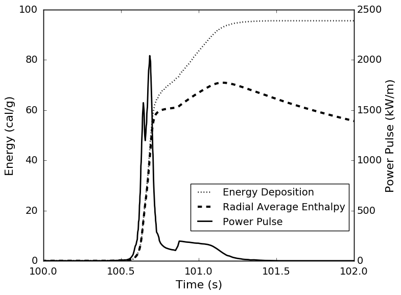
Figure 2: Power pulse, energy deposited and radial averaged fuel enthalpy from the BISON calculation
A more detailed comparison with Falcon shows the time progression of the radial average enthalpy in Figure 3. Both codes show very good agreement throughout the simulation.
The temperature histories for the fuel and cladding are plotted in Figure 4 with the maximum reported values for the fuel and cladding shown in the results table above. The fuel centerline temperature for BISON and Falcon are plotted in Figure 5. The results here again show very good agreement between the two codes for temperature predictions with BISON achieving a slightly higher fuel temperature. While the fuel temperature predictions show good agreement between the two codes the cladding temperatures show differences in excess of 100 degrees. These large differences could be due to the different sodium thermal-hydraulic models used between the codes, or to differences between the gap heat transfer models. Future work is needed to understand the underlying reasons for such large discrepancies.
The cladding outer surface hoop strain relative from HZP conditions and cladding hoop stress is plotted in Figure 6. The maximum cladding hoop strain increase from HZP conditions is 0.63% and the maximum cladding hoop stress is 660 MPa. In this case BISON shows a slightly higher cladding strain than predicted by Falcon and reported by the IRSN. Also shown in Figure 7 is the strain energy density calculations that can be used with the critical strain energy density RIA failure model being developed (Liu et al., 2018). The cladding corrosion thickness calculated by BISON in the results table varied from 60 microns as the bottom to 80 microns at the top of the rodlet, which is the same range measured on the rodlet prior to the RIA experiment. The cladding corrosion thickness can be used to estimate the hydrogen content in the cladding for use with the Critical Strain Energy Density failure model.
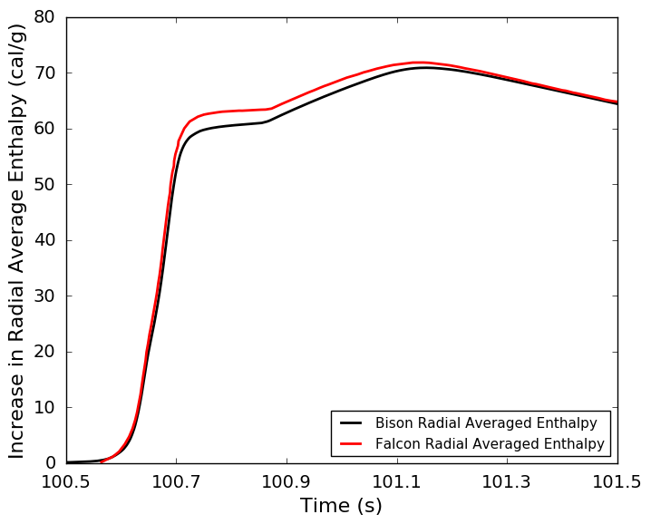
Figure 3: Increase in radial average enthalpy from HZP conditions for BISON and Falcon
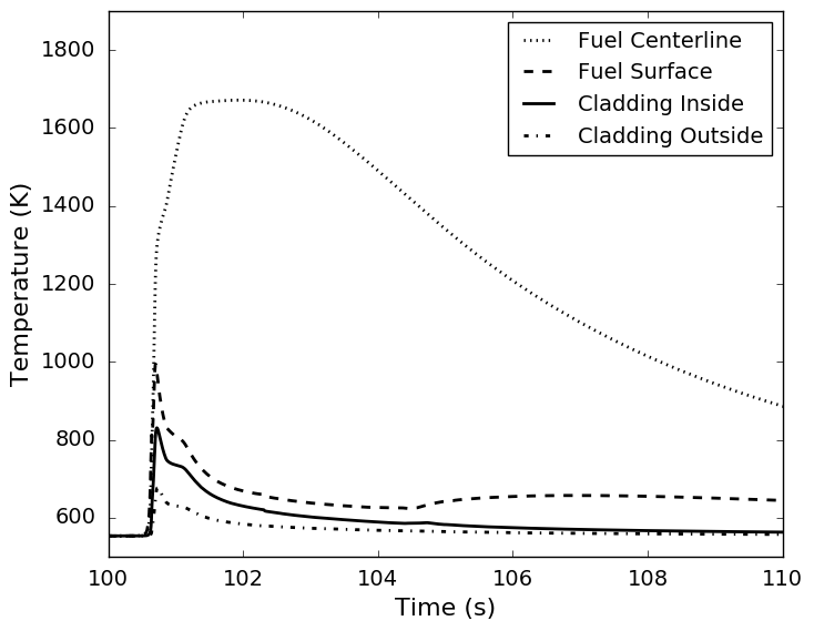
Figure 4: BISON calculated fuel and cladding temperatures
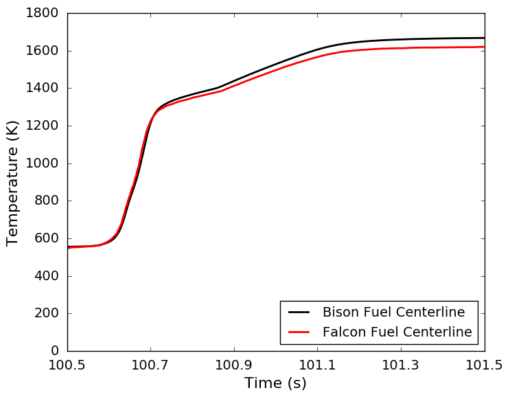
Figure 5: Fuel centerline temperature comparison between BISON and Falcon
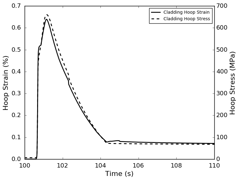
Figure 6: Cladding hoop strain relative from HZP conditions and cladding hoop stress
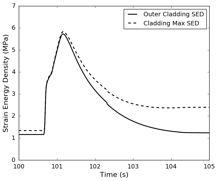
Figure 7: Cladding strain energy density calculations
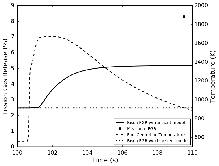
Figure 8: Fission gas release plotted with fuel centerline temperature and measured post-test result
Considerable fission gas release (FGR) has been observed in RIA simulation tests, including the CABRI tests. FGR during an RIA increases cladding loading and the risk of creep-induced cladding rupture by ballooning (e.g., (Schmitz and Papin, 1999)). Hence the need to develop and implement in fuel performance codes accurate models of fission gas behavior and release that are able to deal with the peculiarities of FGR during rapid power/temperature transients. In particular, rapid gas release (burst release) from the fuel grain boundaries occurs during transients through a mechanism of grain-face separation due to micro-cracking. Such mechanism is thought to be responsible for the high FGR observed in transient tests, including RIAs, where the high FGR observed (5-20%, approximately) cannot be interpreted as purely diffusion-based in view of the short time scale of the event. Indeed, micro-cracking has been observed experimentally during microscope examinations of transient-tested fuels, including RIA experiments (Nakamura et al., 1996; Lemoine et al., 2000). As an extension of BISON’s original fission gas model (Pastore et al., 2013; Pastore et al., 2015), a model for burst release due to fuel micro-cracking was recently developed and implemented in BISON (Pastore et al., 2014; Barani et al., 2017; Pastore et al., 2018). This model is applied to the present simulation of the CABRI REP Na-4 experiment. Measured experimental data for FGR were available and are compared to the BISON calculation.
The FGR comparison is very promising. BISON predicted a final FGR of 5.2% compared to the measured value of 8.3%. Note that an uncertainty of at least a factor of 2 exists for FGR predictions in engineering nuclear fuel analysis (Pastore et al., 2015). A plot of the FGR is shown in Figure 8 along with the fuel centerline temperature plotted on the right ordinate. The initial large increase in FGR is highly correlated to the fast increase in fuel temperature, as calculated by the burst release capability in BISON. Note that traditional FGR models typically only account for diffusion-based FGR and will thus tend to strongly underpredict FGR during the short duration of an RIA event. This is demonstrated by comparison with the results from a purely diffusion-based model that differs from the original BISON model only in that the specific transient (micro-cracking) capability is deactivated. This is also shown in Figure 8 with no burst release due to micro-cracking and thus no perceivable increase in FGR from the 2.4% calculated at the end of the base irradiation. Hence, the recently developed transient release capability of the BISON model may represent an important step towards better capturing FGR during RIAs.
Summary
BISON has been shown it is capable of simulating reactivity-initiated accidents with reasonable accuracy to other codes and experimental results. In general BISON provides good results for both fuel radial average enthalpy and fuel temperature predictions which are both used as regulator acceptance criteria for RIA transients. BISON shows good agreement with Falcon on predicted mechanical results such as cladding hoop strain. Finally, the comparison of calculated fission gas release to the experimental data is very encouraging, indicating a promising potential of the recently developed transient fission gas release model in BISON to capture the high FGR during RIAs.
References
- T. Barani, E. Bruschi, D. Pizzocri, G. Pastore, P. Van Uffelen, R.L. Williamson, and L. Luzzi.
Analysis of transient fission gas behaviour in oxide fuel using \mbox BISON and \mbox TRANSURANUS.
Journal of Nuclear Materials, 486:96–110, 2017.[BibTeX]
- KJ Geelhood and WG Luscher.
Fraptran 1.5: integral assessment.
Report NUREG/CR-7023, Vol. 2 Rev. 1, Pacific Northwest National Laborator, 2014.[BibTeX]
- F. Lemoine, B. Cazalis, and H. Rigat.
The role of fission gases on the high burnup fuel behaviour in reactivity initiated accident conditions.
In Proc. of the 10th Int. Symp. on Thermodynamics of Nuclear Materials (SNTM-10). Halifax, Canada, August 6-11 2000.[BibTeX]
- W. Liu, N. Capps, A. Mai, and J. Rashid.
Development of a failure model for RIA conditions.
Technical Report CASL-L3-FMC-FUEL-P16-06, Consortium for Advanced Simulation of LWRs, March 2018.[BibTeX]
- R. Montgomery and D. Sunderland.
Analysis of reactivity initiated accident-simulation tests conducted at the CABRI and NSRR facilities in france and japan.
Technical Report 1002863, Electric Power Research Institute, December 2003.[BibTeX]
- RO Montgomery and YR Rashid.
Evaluation of irradiated fuel during ria simulation tests. final report.
Report TR-106387, Electric Power Research Inst., Palo Alto, CA (United States); ANATECH Research Corp., San Diego, CA (United States), 1996.[BibTeX]
- T. Nakamura, H. Sasajima, T. Fuketa, and K. Ishijima.
Fission gas induced cladding deformation of lwr fuel rods under reactivity initiated accident conditions.
Journal of Nuclear Science and Technology, 33(12):924–935, 1996.
doi:10.1080/18811248.1996.9732034.[BibTeX]
- J Papin, B Cazalis, JM Frizonnet, J Desquines, F Lemoine, V Georgenthum, F Lamare, and M Petit.
Summary and interpretation of the CABRI REP-Na program.
Nuclear technology, 157(3):230–250, 2007.[BibTeX]
- J. Papin, B. Cazalis, J. Frizonnet, E. Federici, and F. Lemoine.
Synthesis of CABRI-RIA tests interpretation.
In Eurosafe Meeting 2003. Paris, France, 2003.[BibTeX]
- G. Pastore, L. Luzzi, V. Di Marcello, and P. Van Uffelen.
Physics-based modelling of fission gas swelling and release in UO$_2$ applied to integral fuel rod analysis.
Nuclear Engineering and Design, 256:75–86, 2013.[BibTeX]
- G. Pastore, D. Pizzocri, S. R. Novascone, D. M. Perez, B. W. Spencer, R.L. Williamson, P. Van Uffelen, and L. Luzzi.
Modelling of transient fission gas behaviour in oxide fuel and application to the BISON code.
In Enlarged Halden Programme Group Meeting, Røros, Norway, September 7-12, volume. 2014.[BibTeX]
- G. Pastore, R. L. Williamson, and C. P. Folsom.
Transient fission gas behavior modeling developments for bison.
Technical Report CASL-U-2018-1610-000, Consortium for Advanced Simulation of LWRs, 2018.[BibTeX]
- Giovanni Pastore, L.P. Swiler, J.D. Hales, S.R. Novascone, D.M. Perez, B.W. Spencer, L. Luzzi, P. Van Uffelen, and R.L. Williamson.
Uncertainty and sensitivity analysis of fission gas behavior in engineering-scale fuel modeling.
Journal of Nuclear Materials, 456:398–408, 2015.
doi:10.1016/j.jnucmat.2014.09.077.[BibTeX]
- Franz Schmitz and Joelle Papin.
High burnup effects on fuel behaviour under accident conditions: the tests CABRI REP-Na.
Journal of Nuclear Materials, 270(1):55–64, 1999.
doi:10.1016/S0022-3115(98)00895-2.[BibTeX]