OECD/NEA/WGFS RIA Fuel Codes Benchmark Case 5
Overview
In September 2009 the Organization for Economic Co-operation and Development (OECD)/Nuclear Energy Agency (NEA)/Committee on the Safety of Nuclear Installations (CSNI) organized a technical workshop on "Nuclear Fuel Behavior during Reactivity Initiated Accidents." One conclusion from a session in the workshop devoted to RIA safety criteria was that fuel rod performance codes are heavily used during the processes of assessing revised safety criteria for the RIA design basis accident. Therefore, as a conclusion of the workshop it was recommended that a benchmark (RIA benchmark Phase I) between fuel performance codes used for assessing RIAs be organized by the Working Group on Fuel Safety (WGFS).
The RIA Fuel Codes Benchmark was organized into two activities (OECDNEA, 2016). The one of interest here is to compare the results of different simulations on simplified cases in order to provide additional bases for understand the differences in modeling of the concerned phenomena. Detailed specifications were prepared in order to prevent as much as possible the variability between the applied model among the different institutions and codes. The full detailed specifications can be found in (OECDNEA, 2016).
Aside from the benchmark case 5 was selected to perform a closer comparison between BISON and FRAPTRAN (Geelhood, 2014). The simplified model will be described below.
Model Description
In order to limit the variability in initial states and properties of high burnup fuel, the cases are limited to a fresh 17x17 PWR type fuel rod. All cases start from ambient conditions and ramp to normal operating conditions during the first 50 seconds and stabilize at those conditions until 100 s, at which point the RIA transient starts. The simulation is concluded at 200 s.
Geometry and Mesh
The fuel is standard UO2 fuel pellets with a diameter of 8.26 mm and a height of 1 cm. No dishing or chamfer is considered in the model. A total fissile column height of 10 cm is specified resulting in a 10 pellet stack. The fuel has a theoretical density of 10970 kg/m with 4% porosity. The cladding is standard Zircaloy-4 material and is 570 m thick. In case 5 the fuel rod is initialized with no initial gap (to simulate a high burnup rod) and the fuel and cladding are considered bonded (no slipping occurs) when the fuel is in contact with the cladding. The plenum volume is defined as 2 cm and is filled with helium at either a low value (20 bar) or a high value (50 bar) at 20 C.
The geometry described in the benchmark specifications was interpreted into a 2D-RZ model for BISON. Owing to the simplicity of the model specified in the benchmark the internal BISON module (FuelPinMeshGenerator was used to generate the mesh. The fuel was defined with 10 radial mesh elements and 40 axial elements. The cladding was defined with 5 radial elements and 40 axial elements. The cladding height was defined to achieve a plenum volume of 2 cm3. The geometry is shown in Figure 1.

Figure 1: BISON fuel rod geometry and mesh. Representation is magnified 3X in the radial direction for clarity.
Material and Behavioral Models
The fuel is modeled using an Elastic model with a Modulus of Elasticity of 200 GPa, a Poisson ratio of 0.345 and thermal expansion coefficient as defined in MATPRO (Siefken et al., 2001). The thermal properties of the fuel are defined using the built-in UO2Thermal module (NFIR correlation) with a porosity of 0.04. The transient power pulse is applied to the fuel as a uniform heat source using the HeatSource module in the Kernels block.
The cladding is modeled using the SolidModel module with the Modulus of Elasticity applied as a function of temperature and a Poisson ratio of 0.3. The thermal properties were defined with the ThermalZry module and the thermal expansion coefficient was applied as a function of temperature from MATPRO. An IsotropicPlasticity module was also applied to the cladding to capture the effect of instantaneous plasticity resulting from the rapid expansion of the fuel into the cladding due to thermal expansion. The yield strength of the cladding was defined as a function of temperature from (Geelhood et al., 2008). No creep models were used due to the small time scales involved in RIA transients.
Boundary and Operating Conditions
For case 5 the benchmark specified "PWR Conditions" for the thermal-hydraulic conditions. These conditions are water coolant at hot zero power (HZP) conditions of 280 C, 155 bar, velocity of 4.0 m/s and a water channel radius of 7.5 mm. For these conditions the CoolantChannel module in BISON was used.
The power pulse will start from zero power at t=100 s and is approximated with a triangular shape. The pulse width will be 30 ms full width at half max (FWHM). The maximum power was defined as 1.0 MW, aimed at initiating departure from nucleate boiling (DNB). The power pulse will result in 531.6 J/g (127.06 cal/g) of energy injected into the fuel. All the power is injected into the UO2 and no contribution will be released in the cladding or coolant. The radial and axial profiles in the fuel are supposed to be flat.
Input files
The BISON input and all supporting files (power histories, axial power profile, fast neutron flux history, etc.) for this case are provided with the code distribution at bison/assessment/LWR/benchmark/RIA_benchmark/case_5/analysis.
Results Comparison
A complete compilation of all the results for all cases and codes was compiled by the OECD (OECDNEA, 2016) comparing each output parameter of interest defined in the benchmark. This report will present and compare the results of BISON and FRAPTRAN simulations for case 5 of the benchmark.
Radial Average Enthalpy
An important parameter to consider when discussing RIA transients is the amount of energy injected into the fuel and the resulting fuel radial average enthalpy. Historically the US Nuclear Regulatory Commission's (USNRC) acceptance criterion for reactivity excursions has been based upon the maximum radial average fuel enthalpy in the fuel rod (USAEC, 1974). Therefore, for safety considerations it is necessary to be able to accurately model the fuel radial average enthalpy of the rodlet. The first two parameters of interest in the benchmark were the energy injected into the rodlet and the variation of radial average enthalpy from the starting conditions at time zero. The energy injected, fuel radial average enthalpy, and power pulse are shown in Figure 2. Figure 3 shows the fuel radial average enthalpy over a longer duration to show the good agreement between the two codes. Good agreement on the radial average enthalpy of the fuel shows that both codes are calculating comparable radial profiles throughout the fuel pellet during the entire simulation.
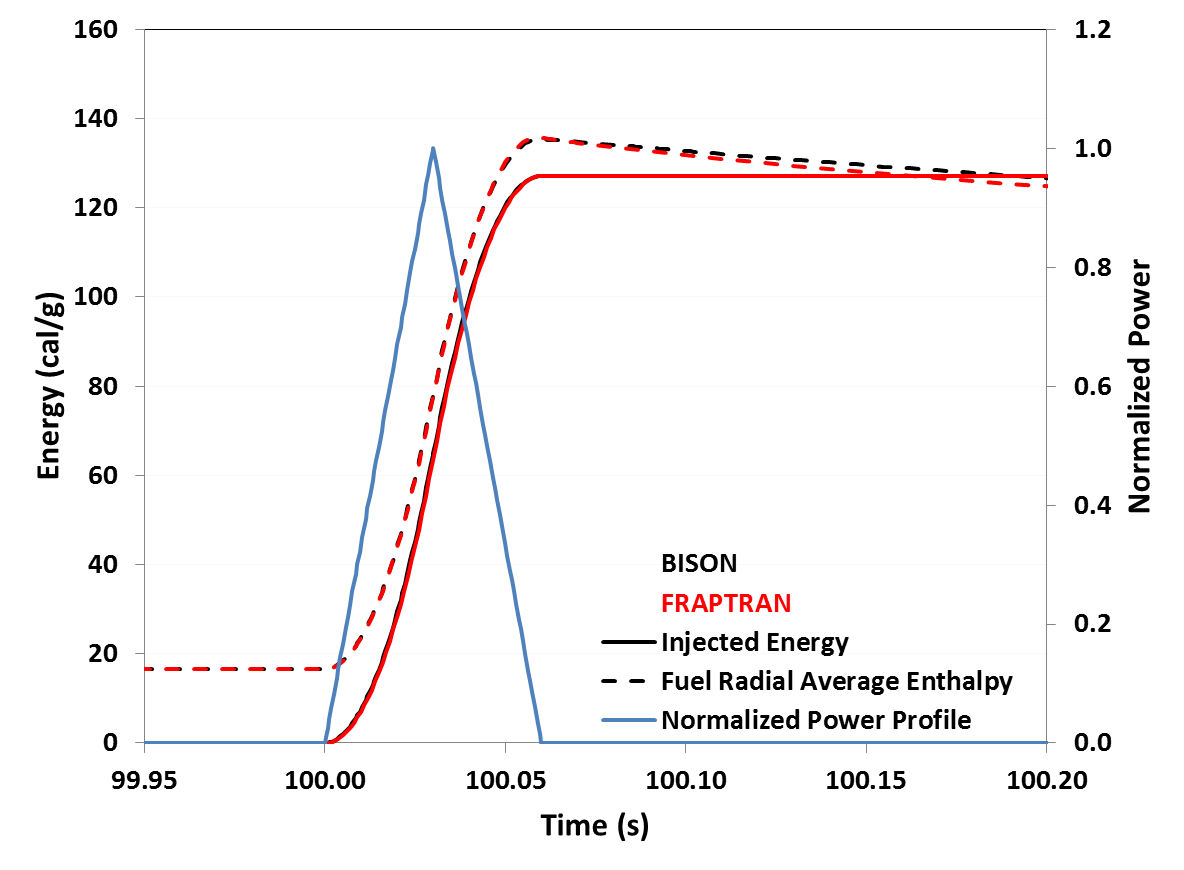
Figure 2: Profile comparisons between FRAPTRAN and BISON for the energy injected into the rodlet and fuel radial average enthalpy shown with the simplified 30 ms FWHM power profile.
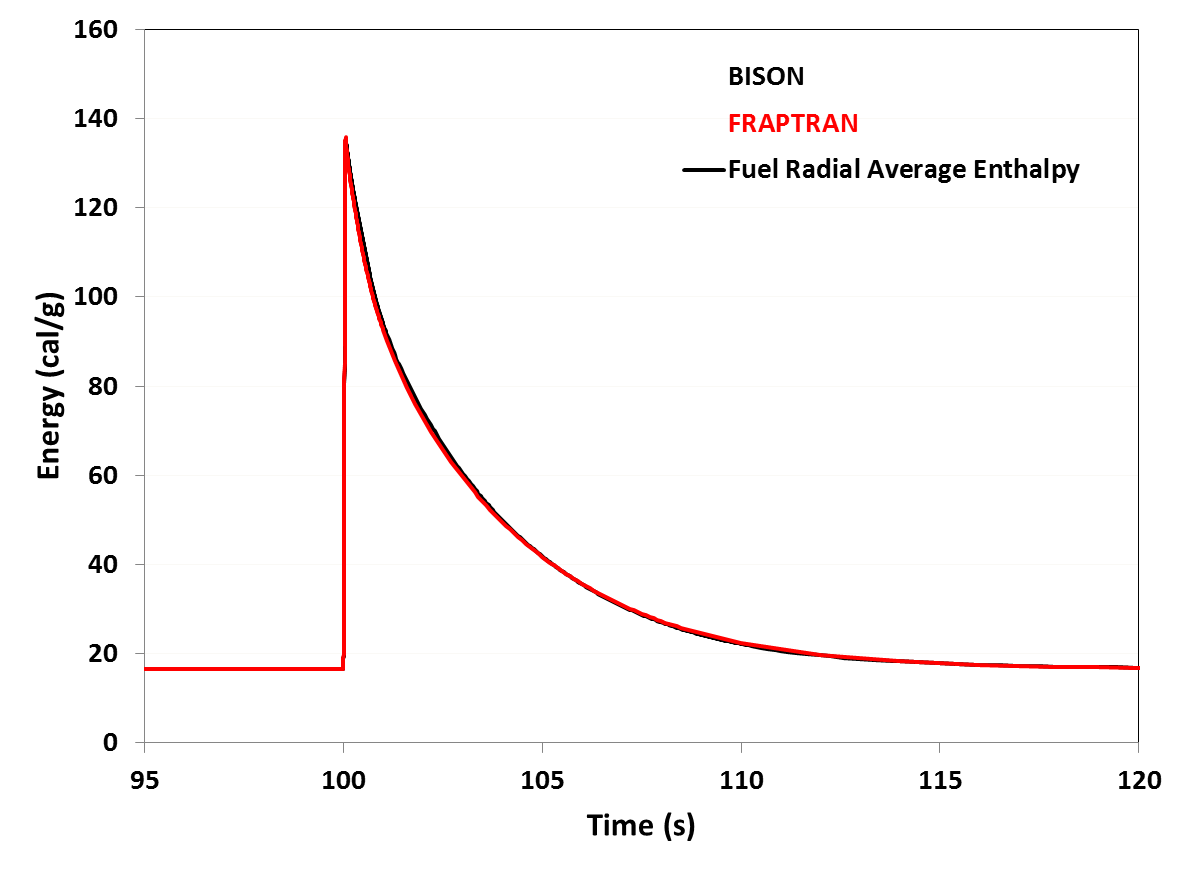
Figure 3: Fuel radial average enthalpy shows excellent agreement between BISON and FRAPTRAN.
Temperatures
The temperature profiles at different radial locations in the rodlet are shown in Figure 4. The fuel centerline temperature shows good agreement between the two codes over the entire transient. The fuel surface and cladding surface temperatures deviate slightly between the two codes. Due to the complexity of the problem and the multiphysics simulation involved it is difficult to pinpoint the cause of the temperature differences between the two codes. There are large variations between the fuel to cladding gap conductance and cladding to coolant heat transfer coefficient between the two codes that will cause differences in temperatures. Also, differences in mechanical models have effects on various mechanisms that affect the energy transport, such as the gap width between the fuel and cladding.
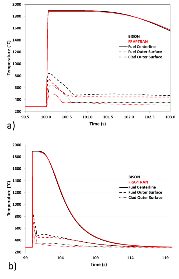
Figure 4: Temperature profiles at different radial locations on the rodlet. a) Temperature profiles during a smaller temporal scale around the power pulse and b) larger temporal scale showing temperature profiles during the cooling of the rodlet.
Hoop Stress and Strain
The combination of such a large and rapid temperature increase and the fuel having a coefficient of thermal expansion twice that of the cladding, results in large hoop strains being applied to the cladding. The hoop strain and corresponding hoop stress at the outer surface of the cladding are shown in Figure 5. During a RIA event the cladding is forced to expand and conform to the expansion of the fuel, therefore the cladding undergoes a displacement controlled problem. The cladding total hoop strain is controlled by the radial expansion of the fuel until separation occurs during cooling. As such, the total hoop strain shows some variation between the codes. They have very similar evolutions, but FRAPTRAN predicts approximately 0.4% more strain than BISON after the pulse. This variation correlates to a difference in the maximum outer radius, 4.209 mm in BISON and 4.219 mm in FRAPTRAN. This is likely due to multiple reasons. First, FRAPTRAN assumes a rigid pellet that cannot yield, while BISON assumes a compliant fuel pellet. Also differences in fuel thermal expansion and plasticity models between codes could result in the variations in calculated strain.
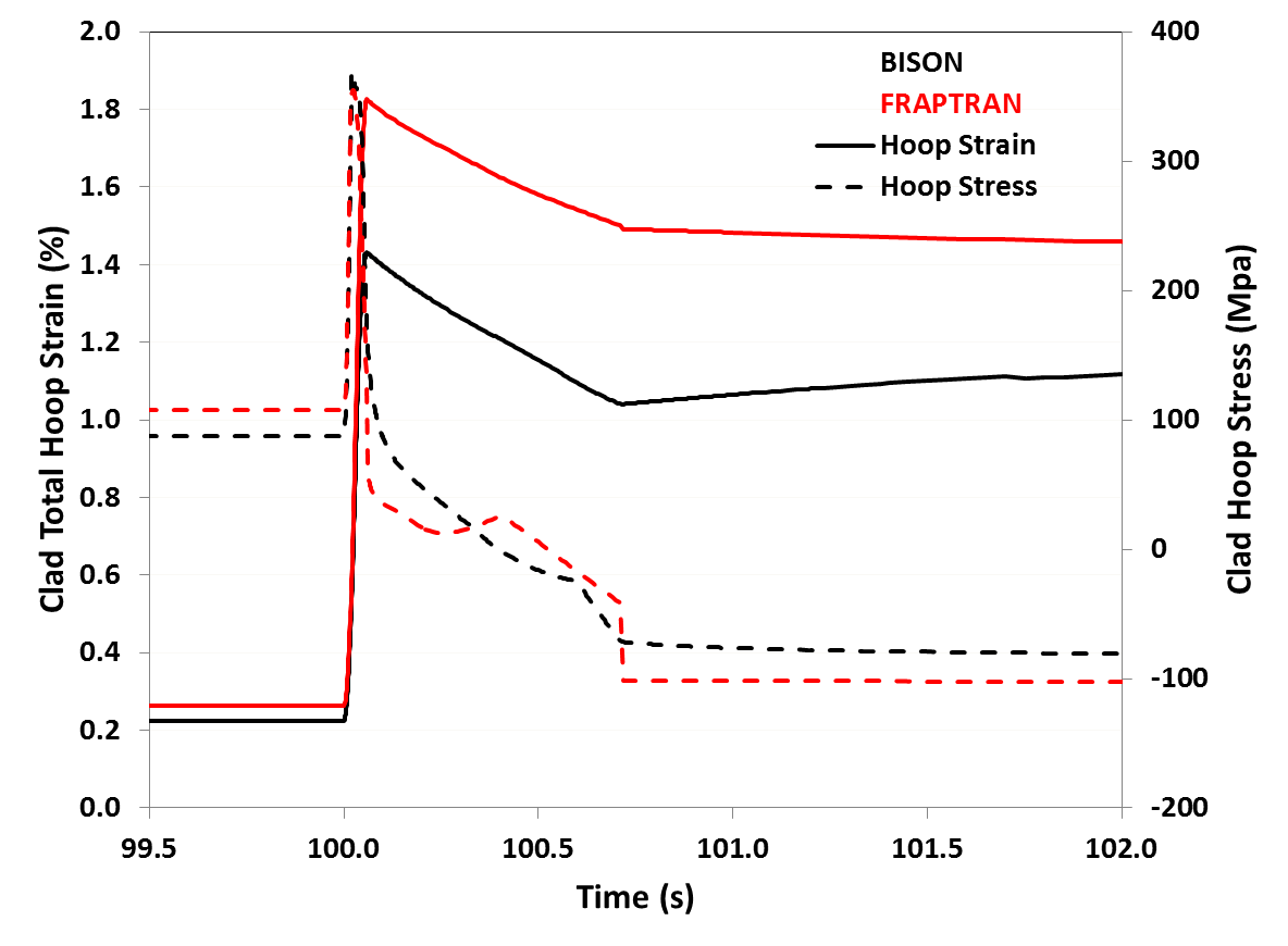
Figure 5: Hoop stress and total hoop strain at the outer surface of the claddingTemperature profiles at different radial locations on the rodlet.
Each code predicted a maximum hoop stress of approximately 340 MPa and were within 20 MPa of each other throughout the transient. The two codes agree reasonably well on the stress, except for a short time just after the power pulse. During this time just after the pulse (100.06-101.0s) there is a complicated trade-off between elastic strain and the development of plastic strain. The increase in plastic strain is due to the decrease of the Zircaloy yield strength as the temperature increases. The temperature dependent yield strength capability was added to BISON as a result of participation in this OECD benchmark.
Summary
A simplified RIA case for a simulated high burnup LWR fuel rod has been successfully modeled using FRAPTRAN and BISON. When comparing different outputs, the trends in both codes for temperature and stresses and strains are similar, and the quantitative agreement is reasonably good. On the other hand there are large differences between the two codes when calculating the HTC's between the fuel and cladding and cladding to water. The large variations in the HTC help explain the small variations in the temperature profiles between the two codes. The differences between the stress and strain profiles can be explained due to differences in the plasticity models and how the mechanics in the fuel are treated (rigid vs. elastic) between the two codes.
Overall, the similarities and differences between the outputs of the two codes provide some insight into the behavior of fuel rods in a RIA scenario. They also emphasize the importance of incorporating all the physics of interest in these fuel performance codes and having proper correlations for the material properties. Code verification and validation remains an important task to ensure safe nuclear fuel development and safety criteria.
References
- K. J. Geelhood.
FRAPTRAN-1.5: a Computer Code for the Transient Analysis of Oxide Fuel Rods.
Technical Report NUREG/CF-7023 Vol.1, Rev.1, U.S. Nuclear Regulatory Commission, 2014.[BibTeX]
- K.J. Geelhood, C.E. Beyer, and W.G. Luscher.
PNNL Stress/Strain correlation for Zircaloy.
Technical Report PNNL-17700, Pacific Northwest National Laboratory, 2008.[BibTeX]
- OECDNEA.
Reactivity Initiated Accident (RIA) Fuel Codes Benchmark Phase-II Report-Volume 1: Simplified Cases Results, Summary and Analysis.
Technical Report NEA/CSNI/R(2016)6, OECD/NEA, 2016.[BibTeX]
- OECDNEA.
Reactivity Initiated Accident (RIA) Fuel Codes Benchmark Phase-II Report-Volume 2: Task No. 1 Specifications.
Technical Report NEA/CSNI/R(2016)6, OECD/NEA, 2016.[BibTeX]
- LJ Siefken, EW Coryell, EA Harvego, and JK Hohorst.
SCDAP/RELAP5/MOD3.3 Code Manual: MATPRO-A Library of Materials Properties for Light-Water-Reactor Accident Analysis.
Technical Report NUREG/CR-6150, Vol.4, Rev.2, U.S. Nuclear Regulatory Commission, 2001.[BibTeX]
- USAEC.
Assumptions Used for Evaluating a Control Rod Ejection Accident for Pressurized Water Reactors.
Technical Report Regulatory Guide 1.77, U.S. Atomic Energy Commission, 1974.[BibTeX]