Example: Homogenous Assembly Fast Reactor Core (ABTR)
We now build a sodium-cooled fast reactor core mesh for the Advanced Burner Test Reactor (ABTR) (Shemon et al. (2015)) using the following key steps.
Create homogenized hexagonal assemblies
Create dummy assemblies needed for core patterning
Combine assemblies into a full core
Delete dummy assemblies
Extrude 2D mesh to 3D
Assign plane-level reporting IDs
Rename outer boundary sidesets for later use in Griffin (optional)
The step-by-step instructions to build the mesh are followed by notes on how to use the mesh in Griffin.
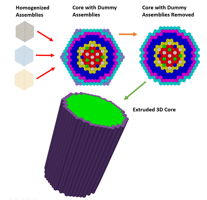
Figure 1: Visualization of meshing steps to build the 3D ABTR core with homogenized assemblies.
Define Homogeneous Hexagonal Assemblies
The first step is to define unique mesh objects for each different assembly type (fuel, control, shield, reflector, dummy). Since this is a homogenized model, we use SimpleHexagonGenerator to create each assembly mesh.
Object
Geometry Features
Hexagonal assembly
Size of 7.3425 (apothem style, meaning the center to wall distance, or half-pitch). No units are implied in the mesh, units will be interpreted by the physics code (generally cm for Griffin)
QUAD elements
Assign unique block ID to each assembly type
Notes
Each assembly type requires its own definition so that different materials can later be assigned to different assemblies (using block id as a differentiating factor)
Alternatively, using "element_type" =
TRIdiscretizes hexagonal assembly into 6 triangles
Example
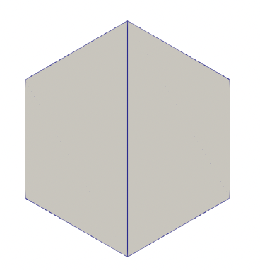
Figure 2: Homogeneous assembly defined with 2 quadrilateral elements.
Listing 1: Input to create a single homogenized assembly.
[Mesh]
  [control]
    type = SimpleHexagonGenerator
    hexagon_size = 7.3425 # Half of the assembly pitch, which is 14.685
    hexagon_size_style = 'apothem' # default
    element_type = QUAD
    block_id = '0'
  []
[]
Define Dummy Assemblies
When we later stitch assemblies into a hexagonal core, the stitcher requires a "perfect" hexagonal pattern. We need to define dummy assemblies to fill the "empty" spots in the perimeter of the core.
Object
Geometry Features
Hexagonal assembly
7.3425 cm half-pitch should be input as 7.3425 units "apothem style"
QUAD elements
Notes
Use a specific ID or name for the dummy in order to delete later in mesh generation process
Example Input
Listing 2: Homogeneous dummy example.
[Mesh]
  [dummy]
    type = SimpleHexagonGenerator
    hexagon_size = 7.3425
    hexagon_size_style = 'apothem'
    element_type = QUAD
    block_id = '997'
  []
[]
Assemble Core Lattice
Now that assemblies have been defined, we stitch the assemblies into a perfect hexagonal pattern to form the initial core. Dummy assemblies are placed in the empty slots and will be deleted in the next step. During this step, reporting IDs called assembly_id are also assigned to each assembly.
Object
Geometry Features
Uses all generated real assemblies and dummy assembly as input
Notes
The parameters "id_name", "assign_type", and "exclude_id" define how the
assembly_idreporting ID will be generated. We exclude the dummy assemblies from being assigned IDs.
Example
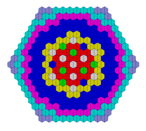
Figure 3: 2D core including dummy assemblies in the "empty" locations.
Listing 3: Homogeneous core example.
[Mesh]
  [core]
    type = PatternedHexMeshGenerator
    inputs = 'control inner_core test_fuel inner_reflector
              outer_core outer_reflector shield dummy'
    pattern_boundary = none # do not add background coolant or a duct around this pattern
    rotate_angle = 0 # do not rotate (default is 90 degrees, i.e. vertex up)
    external_boundary_name = radial # external boundary is called 'radial'
    generate_core_metadata = false # This is a special case. Even though this is a core, we say "false" since the assemblies
    # are homogenized (no pin information) and this is the first invocation of patterning.

    pattern = '  7   7   6   6   6   6   6   6   7   7;
                 7   6   6   5   5   5   5   5   6   6   7;
               6   6   5   5   3   3   3   3   5   5   6   6;
             6   5   5   3   3   3   3   3   3   3   5   5   6;
           6   5   3   3   3   3   4   4   3   3   3   3   5   6;
         6   5   3   3   3   4   4   0   4   4   3   3   3   5   6;
       6   5   3   3   4   4   2   1   1   3   4   4   3   3   5   6;
     6   5   3   3   4   0   1   1   2   1   1   0   4   3   3   5   6;
   7   6   5   3   3   4   1   0   1   1   0   1   4   3   3   5   6   7;
 7   6   5   3   3   4   3   1   1   0   1   1   2   4   3   3   5   6   7;
   7   6   5   3   3   4   1   2   1   1   2   1   4   3   3   5   6   7;
     6   5   3   3   4   0   1   1   0   1   1   0   4   3   3   5   6;
       6   5   3   3   4   4   2   1   1   3   4   4   3   3   5   6;
         6   5   3   3   3   4   4   0   4   4   3   3   3   5   6;
           6   5   3   3   3   3   4   4   3   3   3   3   5   6;
             6   5   5   3   3   3   3   3   3   3   5   5   6;
               6   6   5   5   3   3   3   3   5   5   6   6;
                 7   6   6   5   5   5   5   5   6   6   7;
                   7   7   6   6   6   6   6   6   7   7'
    id_name = 'assembly_id' # automatically assigns assembly_ids
    assign_type = cell # using cell mode
    exclude_id = 'dummy' # don't assign ids to dummy assemblies
  []
[]
Delete Dummy Assemblies
Dummy assemblies were only included to facilitate the core pattern generation and are not part of the final core. They now need to be deleted.
Object
Geometry Features
Remove "dummy" assemblies added for core hex patterning
Notes
Set "new_boundary" to same value as outer boundary in
Mesh/core/external_boundary_nameto update the outer boundary sideset along the location of deleted assemblies
Example
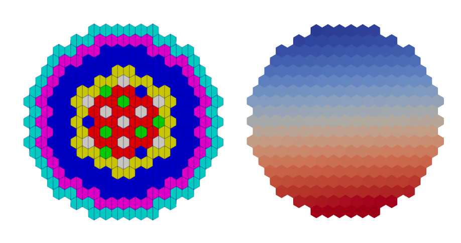
Figure 4: 2D core after deletion of dummy assemblies colored by "subdomain_id"(left) and "assembly_id" (right).
Listing 4: Homogeneous dummy deletion example.
[Mesh]
  [del_dummy]
    type = BlockDeletionGenerator
    input = core
    block = 997 # delete the elements in block 997 (these are the dummy blocks)
    new_boundary = radial # rename the newly exposed outer boundary 'radial'
  []
[]
Extrude 2D core to 3D
The AdvancedExtruderGenerator can be used to perform 2D-to-3D extrusion, allowing users to control elevations through variable extrusion (axial) lengths, axial elements, separate subdomains, additional element integers, and boundaries defined at various elevations.
Object
Geometry Features
Extrude 2D mesh to 3D
Extrude in + direction
Split into multiple intervals, definite heights and number of layers for each
Set top/bottom boundary IDs to be referenced later
Notes
Assign new block IDs to each axial level using "subdomain_swaps". This will allow you to later assign different materials on each axial level
"bottom_boundary" and "top_boundary" parameters are used to assign the boundary IDs of the bottom and top boundary sidesets
Example
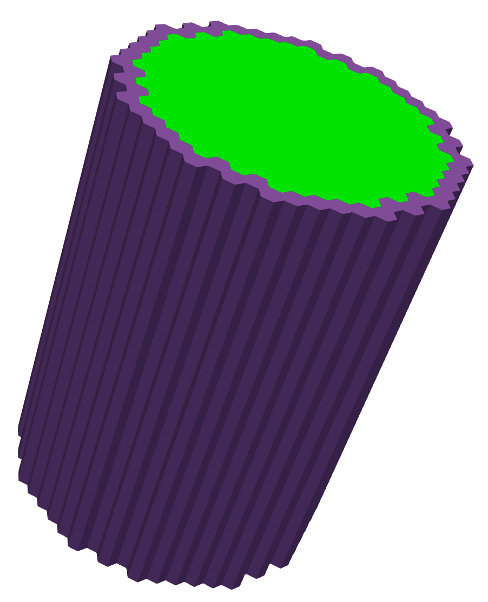
Figure 5: 3D core after extrusion, colored by subdomain IDs.
Listing 5: Homogeneous extrude example.
[Mesh]
  [extrude]
    type = AdvancedExtruderGenerator
    input = del_dummy
    heights = '50.24 42.32 17.98 16.88 16.88 16.88 16.89 16.88 19.76 65.66 31.14 30.15'
    num_layers = '3 2 1 1 1 1 1 1 1 4 2 2'
    direction = '0 0 1'
    top_boundary = 998
    bottom_boundary = 999

    # This changes the block (subdomain) IDs on each axial layer from the original value (0,1,2,3,4,5,6) to something else
    # There are more than 7 materials in the problem so we introduce new block IDs such as 8,9,10,11,12 to account for different materials.

    # The first row changes the bottom layer block ids 0 1 2 3 4 5 6 to block ids 12 12 12 12 12 11
    subdomain_swaps = '0 12 1 12 2 12 3 12 4 12 5 12 6 11;
                       0 9  1 9  2 9  3 8  4 9  5 10 6 11;
                       0 4  1 9  2 9  3 8  4 9  5 10 6 11;
                       0 4  1 1  2 2  3 8  4 3  5 10 6 11;
                       0 4  1 1  2 2  3 8  4 3  5 10 6 11;
                       0 4  1 1  2 2  3 8  4 3  5 10 6 11;
                       0 4  1 1  2 2  3 8  4 3  5 10 6 11;
                       0 5  1 1  2 2  3 8  4 3  5 10 6 11;
                       0 6  1 13 2 13 3 8  4 13 5 10 6 11;
                       0 6  1 14 2 14 3 8  4 14 5 10 6 11;
                       0 7  1 14 2 14 3 8  4 14 5 10 6 11;
                       0 15 1 15 2 15 3 15 4 15 5 15 6 11'
    # The last row changes the block ids on the top layer
  []
[]
Assign Plane-level Reporting IDs
In order to facilitate output processing, we assign plane_id reporting IDs to indicate which elements on the 3D mesh belong to the same axial plane.
Object
Geometry Features
Assign coordinates demarking axial levels in plane_coordinates. These levels should be consistent with how axial levels were defined in AdvancedExtruderGenerator.
Example
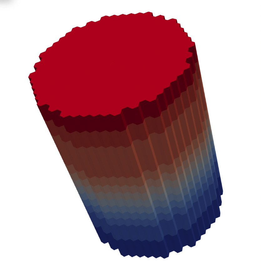
Figure 6: 3D ABTR colored by "plane_id" reporting ID.
Listing 6: Homogeneous plane ID example.
[Mesh]
  [plane_id]
    type = PlaneIDMeshGenerator
    input = extrude
    id_name = plane_id # add reporting ids called 'plane_id'
    plane_coordinates = '0.000 50.240 92.560 110.540 127.420
                         144.300 161.180 178.070 194.950
                         214.710 280.370 311.510 341.660' # elements between these coordinates will be labeled with the same plane_id
  []
[]
(Optional) Rename Outer Boundary Sidesets
Since AdvancedExtruderGenerator requires top and bottom boundary sidesets be defined using numeric IDs, we can assign a name (string) such as 'top' and 'bottom' to these sidesets for easier reference in physics applications.
Object
Notes
Griffin requires the outer boundary sidesets to be defined to apply boundary conditions such as vacuum or reflective boundary conditions
Example
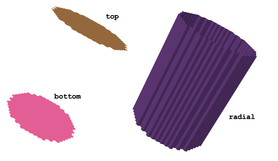
Figure 7: Sideset names and locations of the ABTR core mesh.
Listing 7: Homogeneous boundary rename example.
[Mesh]
  [abtr_mesh]
    type = RenameBoundaryGenerator
    input = plane_id
    old_boundary = '999 998' # The old boundary '999' is renamed 'bottom'.
    # The old boundary '998' is renamed 'top'.
    new_boundary = 'bottom top'
  []
[]
Use of ABTR Mesh in Downstream Physics Code (Griffin)
The Reactor Module creates meshes containing blocks of elements (identified by block ID), groups of elements with similar reporting IDs (identified by different reporting IDs such as pin_id, assembly_id, depletion_id), and groups of curves (2D meshes) or faces (3D meshes) called sidesets (identified by sideset ID). In particular, the blocks and sidesets are used in downstream physics codes to assign materials to mesh elements and to assign boundary conditions.
These assignments are discussed here for Griffin, a MOOSE-based reactor physics code developed under the DOE Nuclear Energy Advanced Modeling and Simulation Program.
Assignment of Material Properties to Blocks
Griffin's MixedNeutronicsMaterial defines the mesh-material mapping explicitly using the subdomain IDs defined on the mesh. Each corresponding material ID defines the cross-section properties for those mesh elements.
The key point is that the block IDs (subdomain_id) in the mesh need to be referenced in the Griffin input file in order to map materials to these blocks. A separate MixedNeutronicsMaterial should be defined in the Griffin input for each unique material ID pertaining to the input mesh.
Listing 8: Homogeneous Griffin block assignment example.
[Materials]
  [icore]
    type = MixedNeutronicsMaterial
    material_id = 1
    block = '  84   85   80   81   79   75   76   82  104  105  100  101   99   95   96  102  124  125  120  121  119  115  116  122  144   145  140  141  139  135  136  142  167  168  162  164  161  156  157  165'
    isotopes = 'pseudo_ICORE'
  []
[]
Assignment of Boundary Conditions to Sidesets
Griffin requires boundary conditions to be applied to all external boundaries of the mesh (generally the top, bottom, and radial periphery for a typical 3D core). Boundary conditions are set in the TransportSystems block of Griffin. These outer boundary sidesets must be assigned to the appropriate boundary condition type (e.g., VacuumBoundary, ReflectingBoundary, etc.).
Listing 9: Homogeneous Griffin Transport Systems example.
[TransportSystems]
  particle = neutron
  G = 33
  VacuumBoundary = 'top bottom radial'
  equation_type = eigenvalue
  [sn]
    scheme = DFEM-SN
    family = L2_LAGRANGE
    order = FIRST
    AQtype = Gauss-Chebyshev
    NPolar = 3
    NAzmthl = 4
    NA = 2
    sweep_type = asynchronous_parallel_sweeper
    using_array_variable = true
    collapse_scattering = true
  []
[]
Generation of CMFD Mesh in Griffin
We briefly touch on mesh generation for the Coarse Mesh Finite Difference (CMFD) acceleration option in Griffin. There are three options:
Option 1: Define "coarse" mesh that is identical to fine mesh
Option 2: Define coarse mesh covering the same geometry as the fine mesh, but with a coarser mesh refinement
Option 3: Define a regular square grid covering the entire mesh domain (and beyond)
This ABTR example uses option 1, where the CMFD acceleration uses the same mesh as the fine mesh, so no additional mesh generation is performed.
Output Postprocessing
MOOSE provides various ways to post-process mesh-based data. The reporting IDs applied to the mesh to designate pin, assembly, and axial zones can be leveraged to post-process reactor core data into tables printing axial pin power distributions by assembly, for example. In this example, integral powers defined as a function of assembly_id and plane_id allow for easy postprocessing of radial and axial powers.
Object
Notes
For each ExtraIDIntegralVectorPostprocessor, a separate CSV file is generated to describe the integral variable quantity as a function of each combination of input reporting ID provided. Alternatively, ExtraIDIntegralReporter can output in JSON file format, which is more suitable for additional data parsing using script languages.
Example
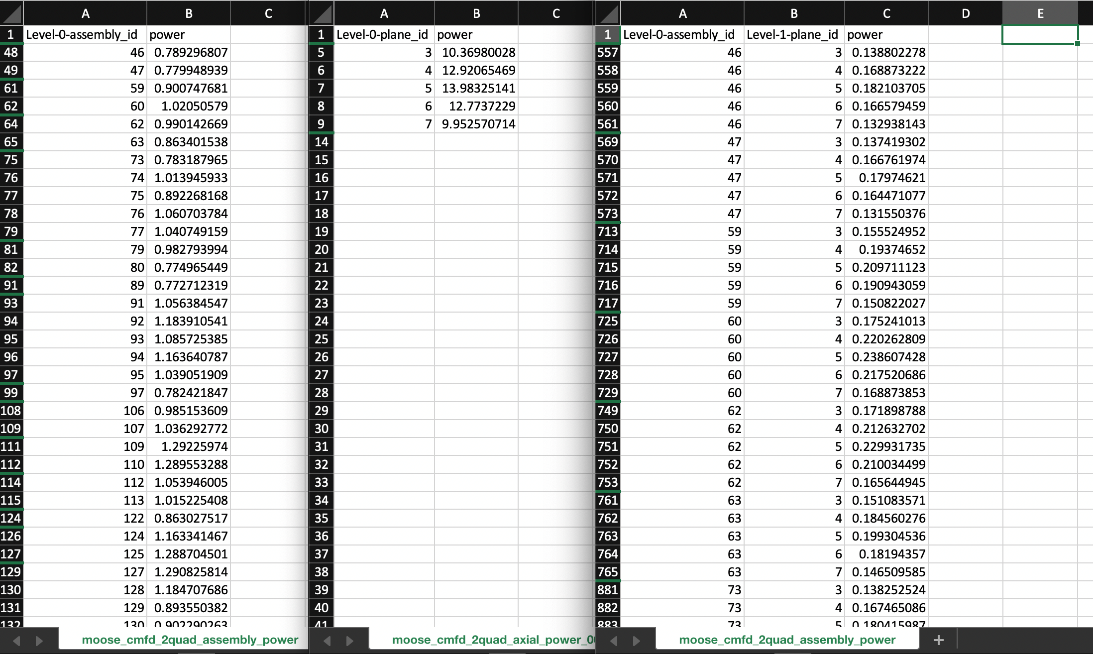
Figure 8: CSV formatted output data from assembly_power_2d (left), axial_power (middle), and assembly_power_3d (right) VectorPostprocessors. Non-zero rows have been filtered out.
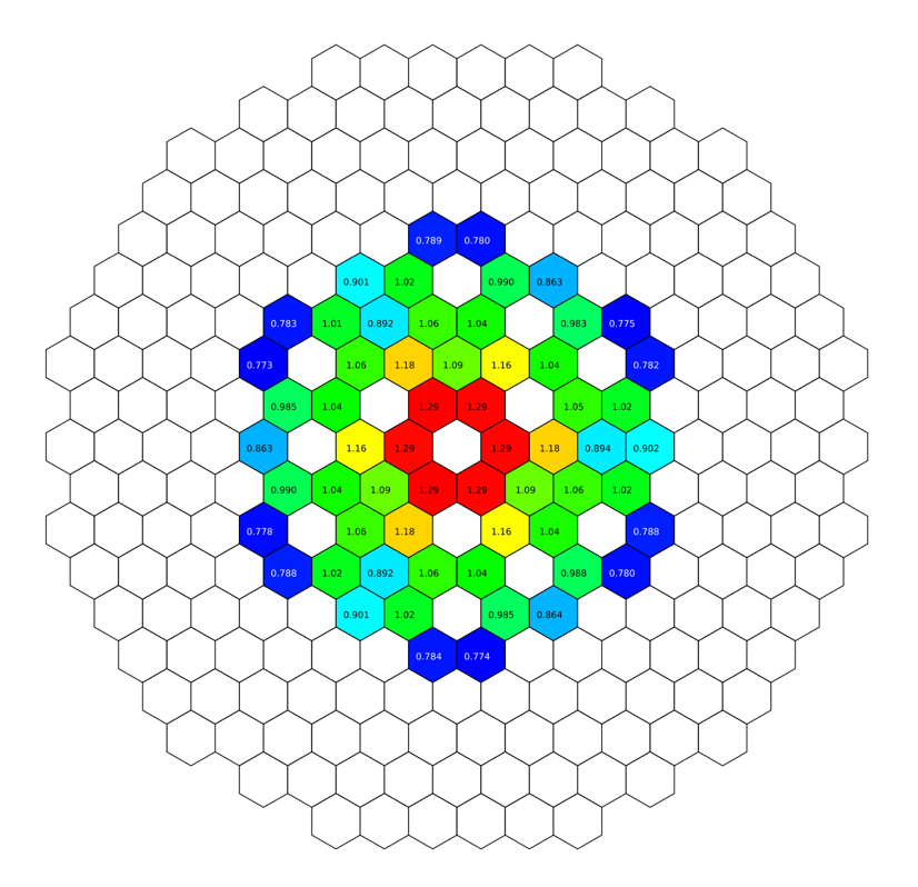
Figure 9: Visualization of normalized axially integrated assembly power density for homogeneous ABTR core, processed from output CSV VectorPostprocessor data. This figure was generated with a custom script taking CSV-formatted power data as input.
Listing 10: Homogeneous Griffin postprocessor example.
[PowerDensity]
  power_density_variable = power
  power = 60.0
[]

[VectorPostprocessors]
  [assembly_power_2d]
    type = ExtraIDIntegralVectorPostprocessor
    variable = 'power'
    id_name = 'assembly_id'
  []
  [axial_power]
    type = ExtraIDIntegralVectorPostprocessor
    variable = 'power'
    id_name = 'plane_id'
  []
  [assembly_power_3d]
    type = ExtraIDIntegralVectorPostprocessor
    variable = 'power'
    id_name = 'assembly_id plane_id'
  []
[]
References
- E. R. Shemon, J. J. Grudzinski, C. H. Lee, J. W. Thomas, and Y. Q. Yu.
Specification of the advanced burner test reactor multi-physics coupling demonstration problem.
Technical Report ANL/NE-15/43, Argonne National Laboratory, 12 2015.
URL: https://www.osti.gov/biblio/1236452, doi:10.2172/1236452.[BibTeX]