Full Core GCMR Multiphysics Model
Mesh Generation
The same mesh as described in Neutronic Modeling of the Whole Core Gas-Cooled Microreactor (GCMR) is used for the neutronics part of the multiphysics model. The mesh is generated using the MOOSE's intrinsic meshing capacity (see Figure 1).

Figure 1: Mesh generation of the GCMR full core model
For heat conduction simulation, a finer mesh is needed to capture the heat flux near key interfaces and surfaces, particularly around the coolant channel surfaces and the external surface of the reactor. This is crucial to keep the energy balance of the model. That is, the heat removed from all the surfaces in the model needs to be reasonably consistent with the reactor power (e.g., >95%) at steady state (see Table 1). As the mesh is generated using MOOSE's intrinsic meshing capabilities enabled by the Reactor module, the finer mesh used for heat conduction is generated using the same mesh input file as the neutronics model, with some mesh density parameters adjusted. To further minimize energy imbalance, quadratic elements should be employed to accurately capture heat flux near critical interfaces and surfaces, as illustrated in Table 1.
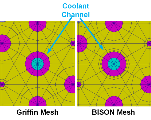
Figure 2: Hierarchy of the GCMR Multiphysics Model
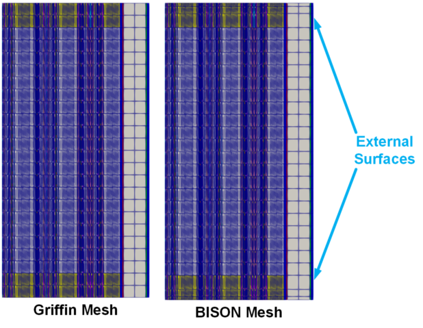
Figure 3: Hierarchy of the GCMR Multiphysics Model
The two major differences in the mesh are illustrated in the following figures. Figure 2 shows the mesh comparison around a coolant channel. Two additional layers of radial elements with biased mesh density are added to the reactor matrix adjacent to each coolant channel. Figure 3 shows the mesh comparison near the top and bottom external surfaces of the reactor. Additional axial layers with biased mesh density are added. To generate a mesh using quadratic elements, users can simply assign tri_type and quad_type as TRI6 and QUAD8. respectively, in the mesh generation input file shown beneath.
#####################################################################################################
# Whole-core mesh for a Gas-cooled Microreactor
# If using or referring to this model, please cite as explained in
# https://mooseframework.inl.gov/virtual_test_bed/citing.html
#####################################################################################################

# Use TRI3/QUAD4 for linear elements (default in this model)
# Use TRI6/QUAD8 for quadratic elements
tri_type = TRI3
quad_type = QUAD4

[GlobalParams]
  tri_element_type = ${tri_type}
  quad_element_type = ${quad_type}
  boundary_region_element_type = ${quad_type}
[]

[Mesh]
  [Coolant_hole]
    # boundary layer setting for coolant channels only for BISON
    background_inner_boundary_layer_width = 0.15
    background_inner_boundary_layer_intervals = 2
    background_inner_boundary_layer_bias = 2
  []
  [extrude]
    # biased axial layers only for BISON
    biases = '2 1 1 1 1 1 0.5'
    num_layers := '3 4 4 4 4 4 3'
  []
[]

!include Griffin_mesh.i
Table 1: Energy balance of the GCMR multiphysics model using the refined BISON mesh
| Power Type | Unit | Value (Linear Elements/This Model) | % | Value (Quadratic Elements) | % |
|---|---|---|---|---|---|
| Reactor Power (1/6 core) | W | 3330000 | 100.00% | 3330000 | 100.00% |
| Heat Transfer to Coolant | W | 3200658 | 96.11% | 3327530 | 99.93% |
| Heat Transfer to Environment | W | 692 | 0.02% | 450 | 0.01% |
| Heat Loss on Symmetry Boundary | W | 1501 | 0.05% | 578 | 0.02% |
Neutronics Model
The same Griffin-based neutronics model as described in Neutronic Modeling of the Whole Core Gas-Cooled Microreactor (GCMR) is used for the neutronics part of the multiphysics model. To reduce the computational cost, the original SN(3,5) NA=2 model is reduced to SN(1,3) NA=2.
Similar to the neutronics only GCMR fuel-core model the neutronics model here uses multi-group cross-sections generated with Serpent-2 and converted into ISOXML format. These cross-sections are tabulated over two grid variables: fuel temperature and hydrogen stoichiometry in the hydride moderator. The fuel temperature values are dynamically provided by the coupled heat conduction model, while the hydrogen content is assumed constant throughout the simulation. The cross-section grid spans fuel temperatures of 725, 825, 925, 1200, and 1700 K, and hydrogen stoichiometry levels of 0, 1, and 2. The same Serpent input described in Neutronic Modeling of the Whole Core Gas-Cooled Microreactor (GCMR) was used to generate the cross-sections with expanded temperature and hydrogen stoichiometry grid values. Although a constant and uniform hydrogen stoichiometry of 1.94 is used in this model, the set up is ready to take the hydrogen stoichiometry from the corresponding model, such as SWIFT (Matthews et al., 2021), in the future.
################################################################################
## NEAMS Micro-Reactor Application Driver                                     ##
## Gas Cooled Microreactor Full Core Steady State                             ##
## Griffin Main Application input file                                        ##
## DFEM-SN (1, 3) with CMFD acceleration                                      ##
## If using or referring to this model, please cite as explained in           ##
## https://mooseframework.inl.gov/virtual_test_bed/citing.html                ##
################################################################################

fuel_blocks = '400 4000 40000 401 4001 40001'
he_channel_blocks = '200 201'
mod_blocks = '100 101'
poison_blocks = '19000 29000 39000 49000 59000 19003 29003 39003 49003 59003 19900 29900 39900 49900 59900 19903 29903 39903 49903 59903'
ref_blocks = '1000 1003 250 600 602 1777 1773'
he_void_blocks = '300 301 604'
cd_poison_blocks = '603'
fecral_blocks = '103'
cr_blocks = '102'
small_parts_blocks = '${cd_poison_blocks} ${fecral_blocks} ${cr_blocks}'
monolith_blocks = '10'

non_he_channel_blocks = '${fuel_blocks} ${mod_blocks} ${poison_blocks} ${ref_blocks} ${he_void_blocks} ${small_parts_blocks} ${monolith_blocks}'

[Mesh]
  # If you do not have a presplit mesh already, you should generate it first:
  # 1. Uncomment all the mesh blocks
  # 2. Use the exodus file in the fmg block
  # 3. Comment the "parallel_type = distributed" line
  # 4. Use moose executable to presplit the mesh
  # Once you have the presplit mesh
  # 1. Comment all the mesh blocks except the fmg block
  # 2. Use the cpr file in the fmg block
  # 3. Uncomment the "parallel_type = distributed" line
  [fmg]
    type = FileMeshGenerator
    file = '../mesh/Griffin_mesh_in.e'
    # file = 'griffin-mesh.cpr'
  []
  [fmg_id]
    type = SubdomainExtraElementIDGenerator
    input = fmg
    subdomains = '10  100 101 102 103 200 201 400 401 4000 4001 40000 40001 300 301 600 602 603 604 1000 1003 19000 29000 39000 49000 59000 19003 29003 39003 49003 59003 19900 29900 39900 49900 59900 19903 29903 39903 49903 59903 1777 1773 250'
    extra_element_id_names = 'material_id '
    extra_element_ids = '803 802 802 810 806 807 807 700 700 701  701  702    702  807 807 811 811 809 807 805  805  764   764   764   764   764   764   764   764   764   764   754   754   754   754   754   754   754   754   754   754   809  809 811'
    #monolith  moderator  moderator_tri  Cr  FECRAL  coolant  coolant_tri  Fuel_in  Fuel_tri_in  Fuel_mid  Fuel_tri_mid  Fuel_out  Fuel_tri_out  Control_hole  Control_hole_tri  CD_Radial1  CD_Radial2  CD_poison  CD_coolant  reflector_quad  reflector_tri  BP0_1  BP0_2  BP0_3  BP0_4  BP0_5  BP0_tr_1  BP0_tr_2  BP0_tr_3  BP0_tr_4  BP0_tr_5  BP1_1  BP1_2  BP1_3  BP1_4  BP1_5  BP1_tr_1  BP1_tr_2  BP1_tr_3  BP1_tr_4  BP1_tr_5  Control_ref  Control_ref_tri  rad_ref
  []
  [coarse_mesh]
    type = GeneratedMeshGenerator
    dim = 3
    nx = 20
    ny = 20
    nz = 20
    xmin = -1.21
    xmax = 1.21
    ymin = -1.21
    ymax = 1.21
    zmin = 0.
    zmax = 2.4
  []
  [assign_coarse_id]
    type = CoarseMeshExtraElementIDGenerator
    input = fmg_id
    coarse_mesh = coarse_mesh
    extra_element_id_name = coarse_element_id
  []
  parallel_type = DISTRIBUTED
[]

[Executioner]
  type = SweepUpdate
  # Richardson iterations
  richardson_abs_tol = 1e-8
  richardson_rel_tol = 1e-9
  richardson_value = eigenvalue
  richardson_max_its = 1000
  inner_solve_type = GMRes
  max_inner_its = 20

  cmfd_acceleration = true
  coarse_element_id = coarse_element_id
  cmfd_eigen_solver_type = newton
  diffusion_prec_type = lu
  prolongation_type = multiplicative
  max_diffusion_coefficient = 1
[]

[Debug]
  check_boundary_coverage = false
  print_block_volume = false
  show_actions = false
[]

[AuxVariables]
  [Tf]
    initial_condition = 725.0
    order = CONSTANT
    family = MONOMIAL
  []
  # We do not calculate hydrogen concentration evolution in this case
  # So nH is just used as a constant
  [nH]
    initial_condition = 1.94
    order = CONSTANT
    family = MONOMIAL
  []
[]

[TransportSystems]
  particle = neutron
  equation_type = eigenvalue
  G = 11
  VacuumBoundary = 'top_boundary bottom_boundary side'
  ReflectingBoundary = 'cut_surf'

  [SN]
    scheme = DFEM-SN
    family = MONOMIAL
    order = FIRST

    AQtype = Gauss-Chebyshev
    NPolar = 1
    NAzmthl = 3
    NA = 2
    n_delay_groups = 6

    sweep_type = asynchronous_parallel_sweeper
    using_array_variable = true
    collapse_scattering = true
    hide_angular_flux = true
  []
[]

[GlobalParams]
  library_file = '../../ISOXML/GCMR_XS_2grid_detailed.xml'
  library_name = GCMR_XS_2grid_detailed
  isotopes = 'pseudo'
  densities = 1.0
  is_meter = true
  # power normalization
  plus = true
  dbgmat = false
  grid_names = 'Tfuel Hdens'
  grid_variables = 'Tf nH'
[]

[PowerDensity]
  power = 3.33e6 # 1/6 of 20 MWth rated power
  power_density_variable = power_density
  integrated_power_postprocessor = integrated_power
[]

[Materials]
  [mod]
    type = CoupledFeedbackMatIDNeutronicsMaterial
    block = '10  100 101 102 103 200 201 400 401 4000 4001 40000 40001 300 301 600 602 603 604 1000 1003 19000 29000 39000 49000 59000 19003 29003 39003 49003 59003 19900 29900 39900 49900 59900 19903 29903 39903 49903 59903 1777 1773 250'
  []
[]

[UserObjects]
  [ss]
    type = TransportSolutionVectorFile
    transport_system = SN
    writing = true
    execute_on = final
  []
[]

[Outputs]
  csv = true
  perf_graph = true
  wall_time_checkpoint = false
  [exodus]
    type = Exodus
    execute_on = 'FINAL'
    enable = false
  []
[]

[MultiApps]
  [bison]
    type = FullSolveMultiApp
    input_files = MP_BISON_ss.i
    execute_on = 'timestep_end'
    keep_solution_during_restore = true
  []
[]

[Transfers]
  [to_sub_power_density]
    type = MultiAppGeneralFieldShapeEvaluationTransfer
    to_multi_app = bison
    variable = power_density
    source_variable = power_density
    from_postprocessors_to_be_preserved = integrated_power
    to_postprocessors_to_be_preserved = power_density
  []
  [from_sub_temp]
    type = MultiAppGeneralFieldShapeEvaluationTransfer
    from_multi_app = bison
    variable = Tf
    source_variable = Tfuel
    to_blocks = ${non_he_channel_blocks}
  []
  [from_sub_temp_he]
    type = MultiAppGeneralFieldNearestLocationTransfer
    from_multi_app = bison
    variable = Tf
    source_variable = Tfuel
    to_blocks = ${he_channel_blocks}
  []
[]Heat Conduction Model
The BISON-based heat conduction model is built upon using a similar approach as described in the Gas-cooled Microreactor Assembly Model Description. The GCMR core design is more complex than the single assembly. In particular, the full core contains three different types of assemblies in its different radial regions instead of a uniform assembly design. However, the key components of the GCMR, including fuel compacts, burnable poison rods, hydride moderator modules, coolant channels, reactor graphite matrix, as well as reflectors, are similar if not the same between the assembly and the full core designs. Therefore, the full core heat conduction model can be established by extending the assembly model to a full core scale using the same material properties.
The coolant channels are designed to be the main heat removal mechanism of the GCMR. Therefore, the external surface of the core is assumed to be effective insulated from the environment. A convective boundary condition with a low heat transfer coefficient (HTC) values of 0.15 W/Km and ambient environment temperature of 300 K.
################################################################################
## NEAMS Micro-Reactor Application Driver                                     ##
## Gas Cooled Microreactor Full Core Steady State                             ##
## BISON Child Application input file                                         ##
## Heat Transfer in Solid Components                                          ##
## If using or referring to this model, please cite as explained in           ##
## https://mooseframework.inl.gov/virtual_test_bed/citing.html                ##
################################################################################

fuel_blocks = '400 4000 40000 401 4001 40001'
# fuel_blocks = 'fuel_in fuel_mid fuel_out fuel_tri_in fuel_tri_mid fuel_tri_out'
he_channel_blocks = '200 201'
# he_channel_blocks = 'coolant coolant_tri'
mod_blocks = '100 101'
# mod_blocks = 'moderator moderator_tri'
poison_blocks = '19000 29000 39000 49000 59000 19003 29003 39003 49003 59003 19900 29900 39900 49900 59900 19903 29903 39903 49903 59903'
# poison_blocks = 'bp0_1 bp0_2 bp0_3 bp0_4 bp0_5 bp0_tr_1 bp0_tr_2 bp0_tr_3 bp0_tr_4 bp0_tr_5 bp1_1 bp1_2 bp1_3 bp1_4 bp1_5 bp1_tr_1 bp1_tr_2 bp1_tr_3 bp1_tr_4 bp1_tr_5'
ref_blocks = '1000 1003 250 600 602 1777 1773'
# ref_blocks = 'reflector_quad reflector_tri rad_ref cd_radial1 cd_radial2 control_ref control_ref_tri'
he_void_blocks = '300 301 604'
# he_void_blocks = 'control_hole control_hole_tri cd_coolant'

cd_poison_blocks = '603'
fecral_blocks = '103'
cr_blocks = '102'
small_parts_blocks = '${cd_poison_blocks} ${fecral_blocks} ${cr_blocks}'
monolith_blocks = '10'

non_fuel_blocks = '${mod_blocks} ${poison_blocks} ${ref_blocks} ${he_void_blocks} ${small_parts_blocks} ${monolith_blocks}'

external_bdries = 'top_boundary bottom_boundary side'
# symmetric_bdries = 'cut_surf'
coolant_channel_bdries = 'coolant_channel_surf'

TsInit = 873.15 # Solid initial temperature
Tcin = 873.15
# radiusTransfer = 0.015 # r + 0.009. Extends past the first mesh cell surrounding the coolant channel.

coolant_full_points_filename = '../component_positions/cc_positions_sixth.txt'

[Problem]
[]

[GlobalParams]
  flux_conversion_factor = 1
[]

[Mesh]
  parallel_type = DISTRIBUTED
  [fmg]
    type = FileMeshGenerator
    file = '../mesh/BISON_mesh_in.e'
    # file = 'bison-mesh.cpr'
  []
  [bdg_full]
    type = BlockDeletionGenerator
    input = fmg
    block = ${he_channel_blocks}
    new_boundary = ${coolant_channel_bdries}
  []
  [mod_surf]
    type = SideSetsBetweenSubdomainsGenerator
    input = bdg_full
    primary_block = 103
    paired_block = 10
    new_boundary = 'mod_surf'
  []
[]

[Variables]
  [temp]
    initial_condition = ${TsInit}
  []
[]

[Kernels]
  [heat_conduction]
    type = HeatConduction
    variable = temp
  []
  [heat_ie]
    type = HeatConductionTimeDerivative
    variable = temp
  []
  [heat_source_fuel]
    type = MatCoupledForce
    variable = temp
    block = ${fuel_blocks}
    v = power_density
    material_properties = power_density_scalar_mat
  []
[]

[AuxVariables]
  [power_density]
    block = ${fuel_blocks}
    family = L2_LAGRANGE
    order = FIRST
    initial_condition = 3e6 # W/m^3
  []
  [Tfuel]
    order = CONSTANT
    family = MONOMIAL
    initial_condition = ${Tcin}
  []
  [hfluid] # Heat Transfer coefficient
    # Calculated by SAM and then transfered with the scaling factor.
    order = CONSTANT
    family = MONOMIAL
    initial_condition = 1000.00
    block = 'monolith reflector_quad reflector_tri' # Can set it on the monolith or coolant.
  []
  [Tfluid] # Coolant temperature.
    order = CONSTANT
    family = MONOMIAL
    initial_condition = ${Tcin}
    block = 'monolith reflector_quad reflector_tri' # Can set it on the monolith or coolant.
  []
  [power_density_scalar]
    family = SCALAR
    order = FIRST
    initial_condition = 1.0
  []
  [Tw_trans] # Coolant temperature.
    order = CONSTANT
    family = MONOMIAL
    initial_condition = ${Tcin}
    block = 'monolith reflector_quad reflector_tri' # Can set it on the monolith or coolant.
  []
[]

[AuxKernels]
  [assign_tfuel_f]
    type = NormalizationAux
    variable = Tfuel
    source_variable = temp
    execute_on = 'timestep_end'
    block = ${fuel_blocks}
  []
  [assign_tfuel_nf]
    type = SpatialUserObjectAux
    variable = Tfuel
    user_object = Tf_avg
    execute_on = 'timestep_end'
    block = ${non_fuel_blocks}
  []
  [Tw_trans] # Coolant temperature.
    type = SpatialUserObjectAux
    variable = Tw_trans
    user_object = Tw_UO
    block = 'monolith reflector_quad reflector_tri'
  []
[]

[BCs]
  [coolant_bc]
    type = CoupledConvectiveHeatFluxBC
    T_infinity = Tfluid
    htc = hfluid
    boundary = ${coolant_channel_bdries}
    variable = temp
  []
  [outside_bc]
    type = ConvectiveFluxFunction # (Robin BC)
    variable = temp
    boundary = ${external_bdries}
    coefficient = 0.15 # W/K/m^2
    T_infinity = 300 # K air temperature at the top of the core
  []
[]

[Materials]
  [power_density_scalar_mat]
    type = ParsedMaterial
    property_name = power_density_scalar_mat
    postprocessor_names = power_density_scalar_pp
    expression = power_density_scalar_pp
  []
  [fuel_matrix_thermal]
    type = GraphiteMatrixThermal
    block = ${fuel_blocks}
    # unirradiated_type = 'A3_27_1800'
    packing_fraction = 0.4
    specific_heat_scale_factor = 1.0
    thermal_conductivity_scale_factor = 1.0
    fast_neutron_fluence = 0 #6.75E+24 # this value is nuetron fluence over 0.1MeV
    temperature = temp
  []
  [monolith_matrix_thermal]
    type = GraphiteMatrixThermal
    block = 'monolith'
    # unirradiated_type = 'A3_27_1800'
    packing_fraction = 0
    specific_heat_scale_factor = 1.0
    thermal_conductivity_scale_factor = 1.0
    fast_neutron_fluence = 0 #6.75E+24 # this value is nuetron fluence over 0.1MeV
    temperature = temp
  []
  [moderator_thermal]
    type = HeatConductionMaterial
    block = ${mod_blocks}
    temp = temp
    thermal_conductivity = 20 # W/m/K
    specific_heat = 500 # random value
  []
  [YH_liner_Cr_thermal]
    type = ChromiumThermal
    block = 102
    temperature = temp
    outputs = all
  []
  [YH_Cladding_thermal]
    type = FeCrAlThermal
    block = 103
    temperature = temp
    outputs = all
  []
  [Poison_blocks_thermal]
    type = HeatConductionMaterial
    block = ${poison_blocks}
    temp = temp
    thermal_conductivity = 92 # W/m/K
    specific_heat = 960 # random value
  []

  [control_rod_thermal]
    type = HeatConductionMaterial
    block = 603 #B4C
    temp = temp
    thermal_conductivity = 92 # W/m/K
    specific_heat = 960 # random value
  []

  [Reflector_thermal]
    type = BeOThermal
    block = ${ref_blocks}
    fluence_conversion_factor = 1
    temperature = temp
    outputs = all
  []

  [airgap_thermal]
    type = HeatConductionMaterial
    block = ${he_void_blocks} # Helium filled in the control rod hole
    temp = temp
    thermal_conductivity = 0.15 # W/m/K
    specific_heat = 5197 # random value
  []

  [fuel_density]
    type = Density
    block = ${fuel_blocks}
    density = 2276.5
  []
  [moderator_density]
    type = Density
    block = ${mod_blocks}
    density = 4.3e3
  []
  [monolith_density]
    type = Density
    block = 10
    density = 1806
  []
  [YH_Liner_Cr_density]
    type = Density
    block = 102
    density = 7190
  []
  [YH_Cladding_density]
    type = Density
    block = 103
    density = 7250
  []
  [Poison_blocks_density]
    type = Density
    block = ${poison_blocks}
    density = 2510
  []
  [control_rod_density]
    type = Density
    block = 603 #B4C
    density = 2510
  []
  [airgap_density]
    type = Density
    block = ${he_void_blocks} #helium
    density = 180
  []

  [reflector_density]
    type = GenericConstantMaterial
    block = ${ref_blocks}
    prop_names = 'density fast_neutron_fluence porosity'
    prop_values = '3000 0 0'
  []
[]

[UserObjects]
  # UserObject to convert the temperature distribution on the inner coolant
  # surface to a 1D profile.
  [Tw_UO]
    type = NearestPointLayeredSideAverage
    variable = temp
    direction = z
    num_layers = 100
    boundary = ${coolant_channel_bdries}
    execute_on = 'TIMESTEP_END'
    points_file = ${coolant_full_points_filename}
  []
  [Tf_avg]
    type = LayeredAverage
    variable = temp
    direction = z
    num_layers = 100
    block = ${fuel_blocks}
  []
[]

[Positions]
  [cc_positions]
    type = FilePositions
    files = ${coolant_full_points_filename}
    outputs = none
  []
[]

[MultiApps]
  [coolant_channel]
    type = TransientMultiApp
    app_type = ThermalHydraulicsApp
    positions_objects = cc_positions
    bounding_box_padding = ' 0.1 0.1 0.1'
    input_files = 'MP_SAM_ss.i'
    execute_on = 'INITIAL TIMESTEP_END'
    max_procs_per_app = 1
    output_in_position = true
    cli_args = "AuxKernels/scale_htc/function='0.997090723*htc'"
    # cli_args: this is a conversion to help with the energy balance.
    sub_cycling = true
  []
[]

[Transfers]
  [Tw_to_coolant]
    # Wall temperature from user object is transferred to fluid domain.
    type = MultiAppGeneralFieldNearestLocationTransfer
    to_multi_app = coolant_channel
    source_variable = Tw_trans # Exists in solid.
    variable = T_wall # Exists in coolant.
  []
  [Tfluid_from_coolant]
    # Fluid temperature from fluid domain is transferred to solid domain.
    type = MultiAppGeneralFieldNearestLocationTransfer
    assume_nearest_app_holds_nearest_location = true
    from_multi_app = coolant_channel
    source_variable = Tfluid_trans
    variable = Tfluid # Exists in solid.
  []
  [hfluid_from_coolant]
    # Convective HTC from fluid domain is transferred to solid domain.
    type = MultiAppGeneralFieldNearestLocationTransfer
    assume_nearest_app_holds_nearest_location = true
    from_multi_app = coolant_channel
    source_variable = hfluid_trans
    variable = hfluid # Exists in solid.
  []
[]

[Preconditioning]
  [SMP]
    type = SMP
    full = true
  []
[]

[Executioner]
  type = Transient

  petsc_options_iname = '-pc_type -pc_hypre_type -ksp_gmres_restart '
  petsc_options_value = 'hypre boomeramg 100'
  line_search = 'none'

  nl_abs_tol = 1e-8
  nl_rel_tol = 1e-8

  start_time = -2.5e5 # negative start time so we can start running from t = 0
  end_time = 0
  dtmax = 1e4
  dtmin = 0.1

  [TimeStepper]
   type = TimeSequenceStepper
   time_sequence = '-250000 -249990 -249980 -249960 -249920 -249840 -249680 -249360 -248720 -247440 -244880 -239760 -230000 -220000 -210000 -200000 -190000 -180000 -170000 -160000 -150000 -140000 -130000 -120000 -110000 -100000 -90000 -80000 -70000 -60000 -50000 -40000 -30000 -20000 -10000 0'
 []
[]

[Postprocessors]
  [fuel_temp_avg]
    type = ElementAverageValue
    variable = temp
    block = ${fuel_blocks}
  []
  [fuel_temp_max]
    type = ElementExtremeValue
    variable = temp
    block = ${fuel_blocks}
  []
  [fuel_temp_min]
    type = ElementExtremeValue
    variable = temp
    block = ${fuel_blocks}
    value_type = min
  []
  [mod_temp_avg]
    type = ElementAverageValue
    variable = temp
    block = ${mod_blocks}
  []
  [mod_temp_max]
    type = ElementExtremeValue
    variable = temp
    block = ${mod_blocks}
  []
  [mod_temp_min]
    type = ElementExtremeValue
    variable = temp
    block = ${mod_blocks}
    value_type = min
  []
  [monolith_temp_avg]
    type = ElementAverageValue
    variable = temp
    block = 10
  []
  [monolith_temp_max]
    type = ElementExtremeValue
    variable = temp
    block = 10
  []
  [monolith_temp_min]
    type = ElementExtremeValue
    variable = temp
    block = 10
    value_type = min
  []
  [heatpipe_surface_temp_avg]
    type = SideAverageValue
    variable = temp
    boundary = ${coolant_channel_bdries}
  []
  [power_density]
    type = ElementIntegralVariablePostprocessor
    block = ${fuel_blocks}
    variable = power_density
    execute_on = 'initial timestep_end transfer'
  []
  [power_density_scalar_pp]
    type = ScalarVariable
    variable = power_density_scalar
    execute_on = 'initial timestep_end'
  []
  [cc_heat]
    type = SideDiffusiveFluxIntegral
    variable = temp
    boundary = ${coolant_channel_bdries}
    diffusivity = thermal_conductivity
  []
  [ext_heat]
    type = SideDiffusiveFluxIntegral
    variable = temp
    boundary = 'side bottom_boundary top_boundary'
    diffusivity = thermal_conductivity
  []
  [mirror_heat]
    type = SideDiffusiveFluxIntegral
    variable = temp
    boundary = 'cut_surf'
    diffusivity = thermal_conductivity
  []
  [total_heat]
    type = ParsedPostprocessor
    pp_names = 'mirror_heat ext_heat cc_heat'
    expression = 'mirror_heat+ext_heat+cc_heat'
  []
[]

[Outputs]
  perf_graph = true
  color = true
  csv = false
  [exodus]
    type = Exodus
    execute_on = 'TIMESTEP_END'
    enable = false
    start_time = -1e-8 # Write Exodus on the last timestep
  []
  [cp]
    type = Checkpoint
    wall_time_interval = '300' # Only write a checkpoint file every 5 minutes of wall time
  []
[]Coolant Channel Model
The coolant channel model also follows a similar input structure to the model from Gas-cooled Microreactor Assembly Model Description. The model utilizes the MOOSE Thermal Hydraulics Module through SAM. With updates to the component type, additional parameters were specified. In the model with FlowChannel1Phase components, the wall heat transfer coefficient and the Darcy friction factors are computed using the Dittus-Boelter correlation and the Churchill correlation, respectively. The HeatTransferFromExternalAppTemperature1Phase component and a LayeredAverage user object were utilized to enable heat transfer at the solid-fluid interface of the model. The number of axial layers used for temperature transfer was set to a total of 40 layers. The component and user object are used collectively to calculate the temperature and heat transfer coefficients and transferring temperature information at every time step via MOOSE’s MultiApp transfer system.
################################################################################
## NEAMS Micro-Reactor Application Driver                                     ##
## Gas Cooled Microreactor Full Core Steady State                             ##
## SAM/THM Grandchild Application input file                                  ##
## Helium coolant channel model                                               ##
## If using or referring to this model, please cite as explained in           ##
## https://mooseframework.inl.gov/virtual_test_bed/citing.html                ##
################################################################################

r_channel = 0.006
Area = '${fparse pi * r_channel^2}'
Height = 2.4 # bottom = 0.000000; top = 2.400000
Ph = '${fparse 2 * pi * r_channel}' # Heated perimeter; Ph = C = 2*pi*r (circumference for round pipe)
Dh = '${fparse 2 * r_channel}' # For circular pipe = D
Vin = 15 # Average flow velocity
Tin = 873.15 # 600 C
Pout = 7e+6 # 7 MPa
layers = 40 # Make sure the number of axial divisions in the fluid domain and solid domain are the same

[GlobalParams]
  initial_p = ${Pout}
  initial_vel = ${Vin}
  initial_T = ${Tin}
  gravity_vector = '0 0 0' # horizontal channel
  rdg_slope_reconstruction = full
  scaling_factor_1phase = '1 1e-2 1e-5'
[]

[FluidProperties]
  [He]
    type = IdealGasFluidProperties
    molar_mass = 0.004003
    mu = 4.2926127588e-05
    k = 0.338475615
    gamma = 1.66
  []
[]

[Closures]
  [custom]
    type = Closures1PhaseNone
  []
[]

[Materials]
  [friction_factor_mat]
    type = ADWallFrictionChurchillMaterial
    vel = vel
    D_h = D_h
    mu = mu
    rho = rho
    f_D = f_D
  []
  [Hw_mat]
    type = ADWallHeatTransferCoefficient3EqnDittusBoelterMaterial
    vel = vel
    D_h = D_h
    mu = mu
    rho = rho
    cp = cp
    k = k
    T = T
    T_wall = T_wall
  []
[]
[Components]
  [pipe1]
    type = FlowChannel1Phase
    position = '0 0.0 0.0'
    orientation = '0 0 1'
    fp = He
    closures = custom
    length = ${Height}
    A = ${Area}
    D_h = ${Dh}
    n_elems = ${layers}
  []

  [ht1]
    type = HeatTransferFromExternalAppTemperature1Phase
    flow_channel = pipe1
    initial_T_wall = ${Tin}
    P_hf = ${Ph}
    T_ext = T_wall
  []

  [inlet] # Boundary conditions
    type = InletVelocityTemperature1Phase
    input = 'pipe1:in'
    vel = ${Vin}
    T = ${Tin}
  []

  [outlet] # Boundary conditions
    type = Outlet1Phase
    input = 'pipe1:out'
    p = ${Pout}
  []
[]

[UserObjects]
  [Tfluid_UO]
    # Creates UserObject needed for transfer
    type = LayeredAverage
    variable = T
    direction = z
    num_layers = ${layers}
    block = 'pipe1'
    execute_on = TIMESTEP_END
  []
  [hfluid_UO]
    # Creates UserObject needed for transfer
    type = LayeredAverage
    variable = htc
    direction = z
    num_layers = ${layers}
    block = 'pipe1'
    execute_on = TIMESTEP_END
  []
[]

[AuxVariables]
  [h_scaled]
    order = CONSTANT
    family = MONOMIAL
    initial_condition = 2500.00
    block = 'pipe1'
  []
  [htc]
    order = CONSTANT
    family = MONOMIAL
    initial_condition = 2500.00
    block = 'pipe1'
  []
  [Tfluid_trans]
    order = CONSTANT
    family = MONOMIAL
    initial_condition = ${Tin}
    block = 'pipe1'
  []
  [hfluid_trans]
    order = CONSTANT
    family = MONOMIAL
    initial_condition = 2500.0
    block = 'pipe1'
  []
[]

[AuxKernels]
  [htc_aux]
    type = ADMaterialRealAux
    property = Hw
    variable = htc
  []
  # HTC scaled by (real geometry surface area)/(model geometry surface area)
  [scale_htc]
    type = ParsedAux
    variable = h_scaled
    expression = '1*htc' # 1 is replaced with the cli_args parameter in its parent app
    coupled_variables =  htc
  []
  [Tfluid_trans]
    type = SpatialUserObjectAux
    variable = Tfluid_trans
    block = 'pipe1'
    user_object = Tfluid_UO
  []
  [hfluid_trans]
    type = SpatialUserObjectAux
    variable = hfluid_trans
    block = 'pipe1'
    user_object = hfluid_UO
  []
[]

[Preconditioning]
  [SMP]
    type = SMP
    full = true
  []
[]

[Executioner]
  type = Transient
  scheme = bdf2
  solve_type = 'NEWTON'
  petsc_options_iname = '-pc_type'
  petsc_options_value = 'lu'

  line_search = basic

  nl_rel_tol = 1e-8
  nl_abs_tol = 1e-9
  nl_max_its = 40

  start_time = -2.5e5 # negative start time so we can start running from t = 0
  end_time = 0
  dt = 1e4
[]

[Outputs]
  console = true
  [out]
    type = Exodus
    execute_on = 'initial timestep_end'
    enable = false
  []
  [csv]
    type = CSV
    execute_on = 'initial timestep_end'
    enable = false
  []
[]

[Postprocessors]
  [_HeatRemovalRate] # Used to measure energy balance
    type = ADHeatRateConvection1Phase
    block = pipe1
    P_hf = ${Ph}
    execute_on = 'TIMESTEP_END'
  []
  [mfr]
    type = ADFlowBoundaryFlux1Phase
    boundary = inlet
    equation = mass
    execute_on = 'TIMESTEP_END'
  []
  [rho_in]
    type = ADSideAverageMaterialProperty
    boundary = 'pipe1:in'
    property = rho
    execute_on = 'TIMESTEP_END'
  []
  [rho_out]
    type = ADSideAverageMaterialProperty
    boundary = 'pipe1:out'
    property = rho
    execute_on = 'TIMESTEP_END'
  []
  [T_in]
    type = ADSideAverageMaterialProperty
    boundary = 'pipe1:in'
    property = T
    execute_on = 'TIMESTEP_END'
  []
  [T_out]
    type = ADSideAverageMaterialProperty
    boundary = 'pipe1:out'
    property = T
    execute_on = 'TIMESTEP_END'
  []
  [P_in]
    type = ADSideAverageMaterialProperty
    boundary = 'pipe1:in'
    property = p
    execute_on = 'TIMESTEP_END'
  []
  [P_out]
    type = ADSideAverageMaterialProperty
    boundary = 'pipe1:out'
    property = p
    execute_on = 'TIMESTEP_END'
  []
  [v_in]
    type = ADSideAverageMaterialProperty
    boundary = 'pipe1:in'
    property = vel
    execute_on = 'TIMESTEP_END'
  []
  [v_out]
    type = ADSideAverageMaterialProperty
    boundary = 'pipe1:out'
    property = vel
    execute_on = 'TIMESTEP_END'
  []
  [htc_avg]
    type = ElementAverageValue
    variable = htc
    execute_on = 'TIMESTEP_END'
  []
[]Note that in this model, the inlet and outlet conditions of the coolant channels are independent from each other for simplicity.
Multiphysics Coupling
The multiphysics model of the fuel-core GCMR is established by interconnecting the three aforementioned single-physics models using a similar hierarchy as what was used for the GCMR assembly simulations. A three-level Griffin-BISON-SAM MultiApp simulation was created for the full GCMR core as illustrated in Figure 4. The coupled Griffin-BISON-SAM multiphysics model can be run using MOOSE-based combined application, BlueCRAB.
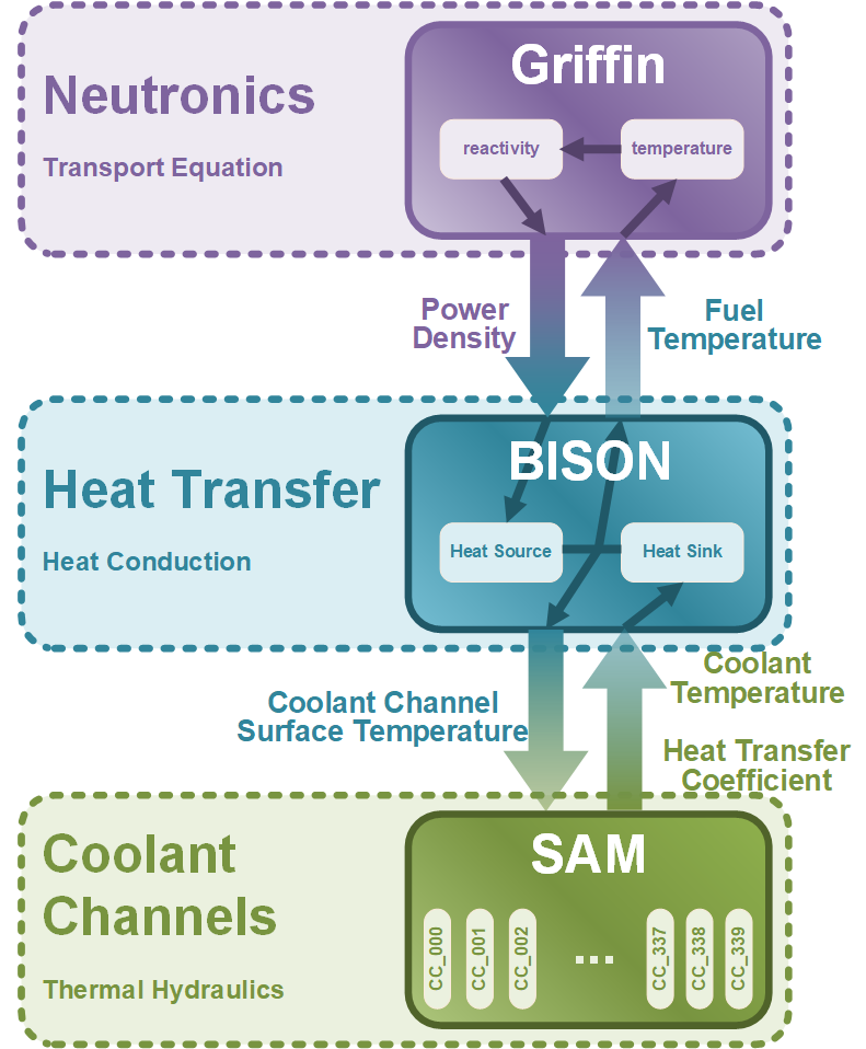
Figure 4: Hierarchy of the GCMR Multiphysics Model
Steady State Simulation Results
The steady-state simulation results of the multiphysics GCMR model are illustrated in Figure 5 and results are summarized in Table 2.
Determined by the inlet coolant temperature, the minimum fuel temperature of the GCMR is around 900 K, the fuel temperature increases along with the axial elevation and reaches 1200 K near the coolant outlet position. As coolant channels are densely distributed, the moderator temperature is comparable with the fuel temperature. Additionally, it is worth noting that the horizontal maximum temperature is not located near the geometric center of the GCMR. Instead, the horizontal maximum temperature is predicted to be in the middle core region, mainly due to the dissimilar assembly designs in different radial regions.
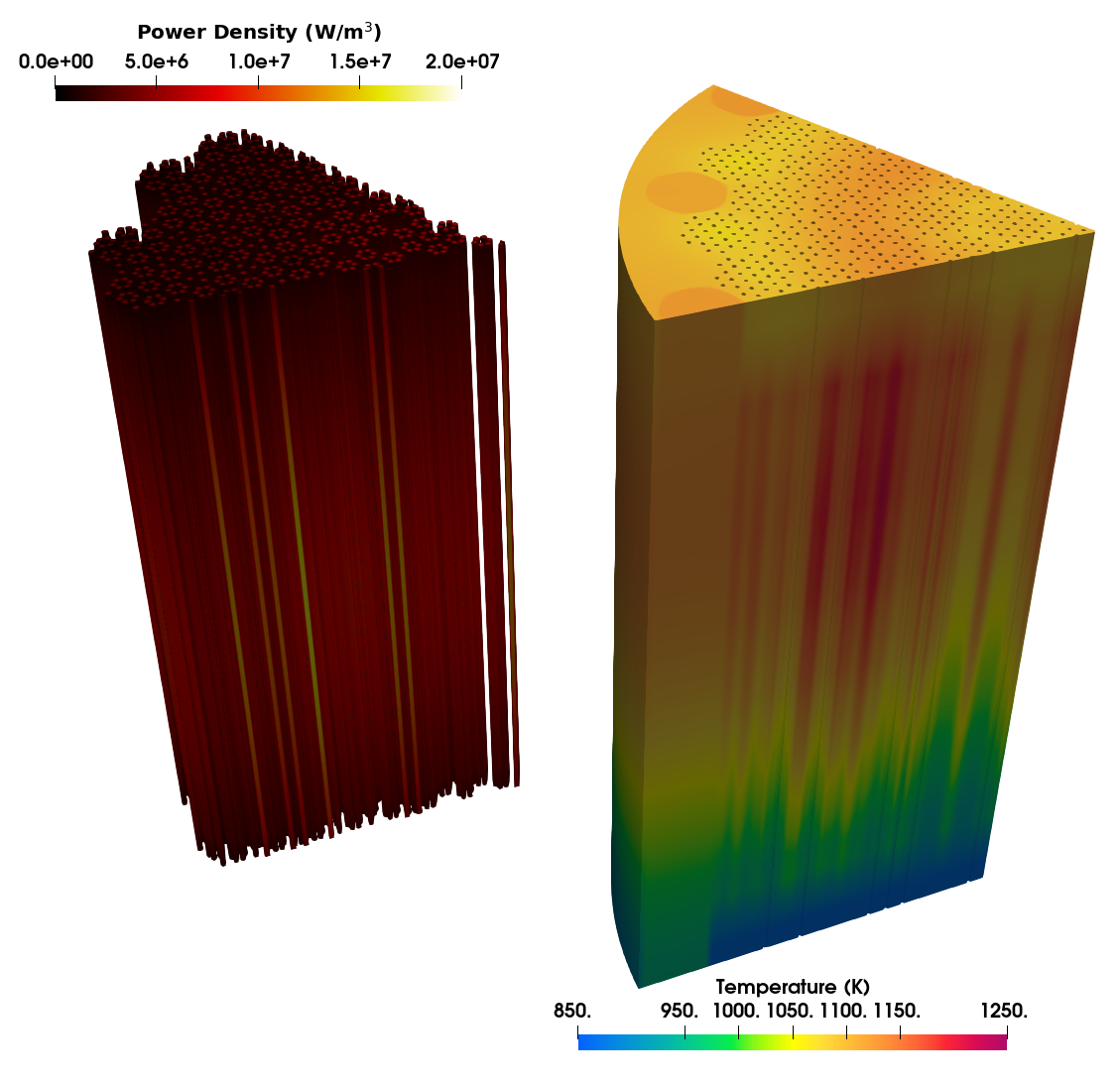
Figure 5: Steady state simulation results of the GCMR multiphysics model
Table 2: Key predicted parameters by the GCMR models
| Parameter | Unit | Value (Linear Elements/This Model) | Value (Quadratic Elements) |
|---|---|---|---|
| Power (1/6 core) | MW | 3.33 | 3.33 |
| K | 1095.69 | 1099.94 | |
| K | 1225.75 | 1230.93 | |
| K | 910.86 | 911.72 | |
| K | 1072.98 | 1075.94 | |
| K | 1180.53 | 1185.48 | |
| K | 912.44 | 912.40 | |
| n/a | 1.0290067 | 1.0288574 |
References
- Christopher Matthews, Aditya Prahlad Shivprasad, and Michael William Donald Cooper.
Metal hydride simulations using swift.
Technical Report LA-UR-21-27538, Los Alamos National Laboratory, 11 2021.[BibTeX]