Balance of Plant system
The startup transient and load follow input file have the same structure and only differ by their initial condition and control system governing the transient. The components are the same.
Fluid flow
The FluidProperties blocks are written in the input file in order to declare the properties of the gas in each loop.
[FluidProperties]
  [he]
    type = IdealGasFluidProperties
    molar_mass = 4e-3
    gamma = 1.67
    k = 0.2556
    mu = 3.22639e-5
  []

  [air]
    type = IdealGasFluidProperties
    molar_mass = 29e-3
    gamma = 1.4
    k = 0.025 # W/(m.K)
    mu = 1.8e-5 # Pa.s
  []
[]The friction factor and heat transfer coefficient in each loop are defined using the Closure1PhaseTHM closures and the default options:
The heat transfer coefficient sub block is defined using the Dittus-Boelter correlation (ADWallHeatTransferCoefficient3EqnDittusBoelterMaterial).
The friction factor is defined using the Churchill equation (ADWallFrictionChurchillMaterial).
[Closures]
  [thm]
    type = Closures1PhaseTHM
  []
[]Solid Materials
The solid materials of the many heat structures are declared using a SolidProperties block. It gives the properties of three materials: the H-451 graphite and the fuel, used in the core, and the steel, used in the heat exchanger and in the recuperator. Each solid material is defined using the ThermalFunctionSolidProperties type. Constant densities, thermal conductivities and specific heats are provided.
[SolidProperties]
  [graphite]
    type = ThermalFunctionSolidProperties
    rho = 2160 # kg/m3
    k = 40 # W/(m.K)
    cp = 2100 # J/(kg.K)         approximate mean specific heat of graphite between 800 K (coolant) and 1400 K (fuel)
  []
  [fuel]
    type = ThermalFunctionSolidProperties
    rho = 10970 # kg/m3
    k = 5 # W/(m.K)
    cp = 300 # J/(kg.K)
  []
  [steel]
    type = ThermalFunctionSolidProperties
    rho = 8050 # kg/m3
    k = 45 # W/(m.K)
    cp = 466 # J/(kg.K)
  []
[]Components
Geometry
The geometry is defined using the Components system. Each component is defined using a position, orientation and length for 1D components. A width is also defined for 2D components (heat structures). Channels are defined using the FlowChannel1Phase components and heat structures are defined using the HeatStructureCylindrical or HeatStructurePlate depending on the geometry.
Initial conditions
A common initial temperature is chosen for the whole system. It is done to avoid irregular effects in the first few seconds of the simulation due to a high temperature difference between the primary and secondary sides in the heat exchanger (hx). The only exceptions are the sec_pipe1 and hot_leg of the secondary loop, which are respectively connected to the inlet and outlet of the cycle. Their initial temperature is 300 K.
In the primary loop, a 90 bar pressure is defined and is equal to the steady state pressure in that loop. The secondary loop is initialized to the atmospheric pressure.
The velocities are initialized at a very small non-zero value.
Channels
All the channels are defined using FlowChannel1Phase blocks. Depending on the loop, helium or air is declared as the fluid. The initial conditions are those chosen for each loop.
Primary loop components
To make it easier to see the space variations of the pressure, mass flow rate, temperature and power through the primary loop using the "PlotOverLine" filter in Paraview, all its components, except the pri_pipe6, are on the same axis and in the same direction. The pri_pipe6 has the opposite direction and is used to close the cycle.
Core
The core geometry is simplified to be able to use a 1D-2D representation. Only one coolant channel is used representing all the coolant channels in the core. It is coupled to a single heat structure representing the moderator and fuel as shown in Figure 1.
This structure is defined using a HeatStructureCylindrical component. The radius of the coolant channel is defined in the design description, and the graphite and fuel outer radii are defined to preserve to their total volume. The average quantity of graphite and of fuel per coolant channel is then computed and used to define the simplified geometry of the heat structure: a cylindrical heat structure, with a coolant cylinder in the middle of a hollow graphite cylinder, itself in a hollow fuel cylinder. This structure is replicated for each coolant channels using the num_rods parameter.
The geometrical parameters of the coolant itself are adapted to represent all the coolant channels:
the channel section
Ais equal to the sum of all the sections of the real coolant channels, because it conducts the same mass flow rate than all the real coolant channels,the channel heating perimeter
P_hfis equal to the sum of the perimeters of all the real channels,the hydraulic diameter
D_his the one of a real coolant channel because it is linked with the frictions and pressure drop.
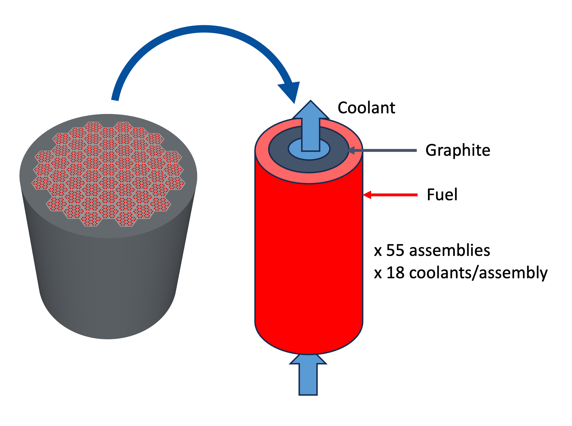
Figure 1: Method used to simplify the core
[Components]
  [core]

    [coolant_channel]
      type = FlowChannel1Phase
      position = '${pri_x_core} ${pri_y_core} 0.'
      orientation = '1 0 0'
      length = ${core_length_channel}
      n_elems = ${core_channel_n_elems}
      A = '${fparse pi * core_nb_coolant_tot * core_radius_coolant * core_radius_coolant}'
      D_h = '${fparse 2 * core_radius_coolant}'

      fp = he
      initial_p = ${pri_press}
      initial_vel = ${vel_ini_pri}
    []

    [hs]
      type = HeatStructureCylindrical
      position = '${pri_x_core} ${pri_y_core} 0.'
      orientation = '1 0 0'
      length = ${core_length_channel}
      n_elems = ${core_channel_n_elems}

      inner_radius = ${core_radius_coolant}
      num_rods = ${core_nb_coolant_tot}
      initial_T = 400

      names = 'graphite_layer fuel_layer'
      widths = '${core_radius_equiv_mod} ${core_radius_equiv_complete_hs}'
      solid_properties = 'graphite fuel'
      solid_properties_T_ref = '0 0' # These materials are independent of temp.
      n_part_elems = '3 3'
      offset_mesh_by_inner_radius = true
    []

    [core_heating]
      type = HeatSourceFromTotalPower
      hs = core/hs
      regions = fuel_layer
      power = total_power
    []

    [core_ht]
      type = HeatTransferFromHeatStructure1Phase
      flow_channel = core/coolant_channel
      hs = core/hs
      hs_side = inner
      P_hf = '${fparse pi * 2 * core_radius_coolant * core_nb_coolant_tot}'
    []
  []
[]A power of 15 MWth is declared using a power block of TotalPower type.
[Components]
  [total_power]
    type = TotalPower
    power = ${tot_power}
  []
[]Pressurizer
A pressurizer is added to maintain a 90 bar pressure during the whole simulation, using a InletStagnationPressureTemperature1Phase component. It is located between the core and the heat exchanger, in order to have a pressure as close as possible to 90 bar in the core.
[Components]
  [pressu]
    [pri_jct_2_3_prz]
      type = VolumeJunction1Phase
      connections = 'pri_pipe2:out pri_pipe3:in pressu/pipe_prz:in'
      position = '${pri_x_pipe3} ${pri_y_pipe3} 0.'
      volume = 1e-3
      initial_p = ${pri_press}
      initial_vel_x = ${vel_ini_pri}
      use_scalar_variables = false
    []
    [pipe_prz]
      type = FlowChannel1Phase
      position = '${pri_x_pipe3} ${pri_y_pipe3} 0.'
      orientation = '0 1 0'
      length = ${PRI_L_prz}
      n_elems = ${pri_pipe_prz_n_elems}
      A = '${pri_pipes_area}'
      D_h = '${pri_pipes_D_h}'

      fp = he
      initial_p = ${pri_press}
      initial_vel = ${vel_ini_pri}
    []
    [prz]
      type = InletStagnationPressureTemperature1Phase
      p0 = ${pri_press}
      T0 = ${T_ini}
      input = 'pressu/pipe_prz:out'
    []
  []
[]Heat exchanger
The heat exchanger is modeled as a 2 meters-high structure, composed of couples of primary and secondary channels (see Figure 2 ) which are replicated 20,000 times. Their diameters are respectively 3 mm and 5 mm. They are defined using FlowChannel1Phase components. They are separated by a 1 mm steel wall defined using a HeatStructureCylindrical component, and the flow directions are opposite. The heat transfers are declared with HeatTransferFromHeatStructure1Phase. The wall is used as heat structure and each channel as the heated flow channel.
The same principle as for the core coolant channel is used to define the A section, P_hf heating perimeter and D_h hydraulic diameter parameters. The replication of the couple is done using the num_rods parameter of the wall block.
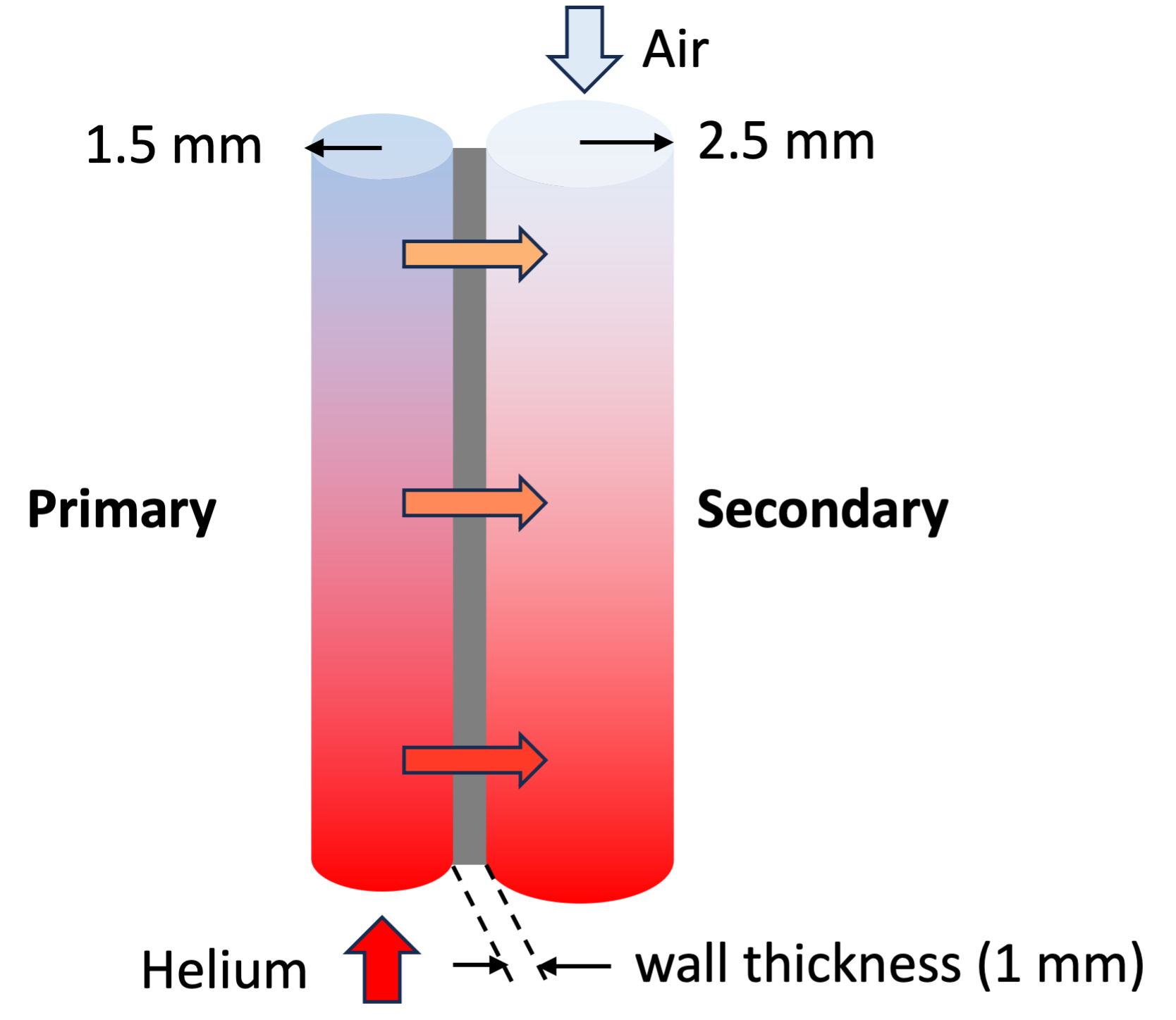
Figure 2: Couple of primary and secondary flow channels in the heat exchanger
[Components]
  [hx]
    [pri]
      type = FlowChannel1Phase
      position = '${pri_x_hx} ${pri_y_hx} 0.'
      orientation = '1 0 0'
      length = ${hx_length}
      n_elems = ${hx_n_elems_axial}
      A = '${fparse pi * hx_nb_channels * hx_dia_pri * hx_dia_pri * 0.25}'
      D_h = ${hx_dia_pri}

      fp = he
      initial_p = ${pri_press}
      initial_vel = ${vel_ini_pri}
    []

    [ht_pri]
      type = HeatTransferFromHeatStructure1Phase
      hs = hx/wall
      hs_side = inner
      flow_channel = hx/pri
      P_hf = '${fparse pi * hx_nb_channels * hx_dia_pri}'
    []

    [wall]
      type = HeatStructureCylindrical
      length = ${hx_length}
      n_elems = ${hx_n_elems_axial}
      n_part_elems = 1
      names = 'hx_wall'
      orientation = '1 0 0'
      position = '${pri_x_hx} ${pri_y_hx} 0.'
      widths = '${hx_wall_thickness}'
      solid_properties = 'steel'
      solid_properties_T_ref = '0' # This material is independent of temp.
      inner_radius = '${fparse hx_dia_pri / 2}'
      num_rods = ${hx_nb_channels}
    []

    [ht_sec]
      type = HeatTransferFromHeatStructure1Phase
      hs = hx/wall
      hs_side = outer
      flow_channel = hx/sec
      P_hf = '${fparse pi * hx_nb_channels * hx_dia_sec}'
    []

    [sec]
      type = FlowChannel1Phase
      position = '${sec_x_hx} ${sec_y_hx} 0.'
      orientation = '-1 0 0'
      length = ${hx_length}
      n_elems = ${hx_n_elems_axial}
      A = '${fparse pi * hx_nb_channels * hx_dia_sec * hx_dia_sec * 0.25}'
      D_h = '${hx_dia_sec}'

      fp = air
      initial_p = ${p_sec}
      initial_vel = ${vel_ini_sec}
    []
  []
[]Pump
The pressure drop is compensated by a pump declared as a ShaftConnectedPump1Phase component. It is connected to a motor, declared as ShaftConnectedMotor, and a shaft, declared as Shaft, which provide its hydraulic torque. The rated values of the pump (volumetric flow rate, head, density, torque, shaft speed) are defined as close as possible to the operating values (Table 1).
Table 1: Pump - comparison between the rated and steady state values
| Parameter | Rated value | Steady state value |
|---|---|---|
| Density (kg/m3) | 5 | 4.86 |
| Volumetric flow rate (m3/s) | 2 | 1.92 |
| Pump head (m) | 350 | 293 |
| Shaft speed (rad/s) | 5 | 4.5 |
| Torque (N.m) | 50 | 42 |
The performance curves (the Bingham head and torque functions) are defined using a head_fcn and a torque_fcn functions in the Functions block, which imports data from csv files. The motor torque is set to match the nominal mass flow rate in the loop.
[Components]
  [circ]
    [pump]
      type = ShaftConnectedPump1Phase
      inlet = 'pri_pipe4:out'
      outlet = 'pri_pipe5:in'
      position = '${pri_x_pipe5} ${pri_y_pipe5} 0.'
      A_ref = ${pump_area}
      scaling_factor_rhoEV = 1e-5
      volume = ${pump_volume}
      inertia_coeff = ${pump_inertia_coeff}
      inertia_const = ${pump_inertia_const}
      omega_rated = ${pump_omega_rated}
      speed_cr_I = ${pump_speed_cr_I}
      speed_cr_fr = ${pump_speed_cr_fr}
      torque_rated = ${pump_torque_rated}
      volumetric_rated = ${pump_volumetric_rated}
      head_rated = ${pump_head_rated}
      tau_fr_coeff = ${pump_tau_fr_coeff}
      tau_fr_const = ${pump_tau_fr_const}
      head = head_fcn
      torque_hydraulic = torque_fcn
      density_rated = ${pump_density_rated}
      initial_p = ${pri_press}
      initial_vel_x = ${vel_ini_pri}
      use_scalar_variables = false
    []

    [motor]
      type = ShaftConnectedMotor
      inertia = ${pri_motor_inertia}
      torque = ${pri_motor_torque}
    []

    [shaft]
      type = Shaft
      connected_components = 'circ/motor circ/pump'
      initial_speed = ${shaft_initial_speed}
    []
  []
[]Secondary loop components
The secondary loop is a recuperated open-air Brayton cycle and is similar to the one described in the Thermal-Hydraulics Module Modeling Guide.
This input file has been adapted to achieve the nominal operating condition. In particular, the rated values for the turbine and the compressor and the geometrical parameters were adjusted.
The detail of the components is given below.
Boundary Conditions
Stagnation pressure and temperature are defined at the inlet of the Brayton cycle using an InletStagnationPressureTemperature1Phase component with = 300 K and = 1 bar.
[Components]
  [inlet]
    type = InletStagnationPressureTemperature1Phase
    input = 'sec_pipe1:in'
    p0 = ${p_ambient}
    T0 = ${T_ambient}
  []
[]The pressure is prescribed at the outlet using an Outlet1Phase component.
[Components]
  [outlet]
    type = Outlet1Phase
    input = 'hot_leg:out'
    p = ${p_ambient}
  []
[]Shaft
The compressor, the turbine, the generator, and the motor are on the same shaft. This component is defined using a Shaft type.
[Components]
  [shaft]
    type = Shaft
    connected_components = 'motor compressor turbine generator'
    initial_speed = ${speed_initial}
  []
[]Compressor
The compressor is defined using the ShaftConnectedCompressor1Phase component type. The A_ref section is adapted to admit enough air in the cycle. The rated values (omega_rated, mdot_rated, c0_rated, rho0_rated, see Figure 3) are defined to match as close as possible to the operating values. The results are given, with those of the turbine, in the next table.
These rated parameters are associated to the efficiency and pressure ratio functions of the compressor, defined in the Functions block and using data from csv files.
[Components]
  [compressor]
    type = ShaftConnectedCompressor1Phase
    position = '${sec_x_pipe2} ${sec_y_pipe2} 0'
    inlet = 'sec_pipe1:out'
    outlet = 'sec_pipe2:in'
    A_ref = ${A_ref_comp}
    volume = ${V_comp}

    omega_rated = ${speed_rated}
    mdot_rated = ${rated_mfr}
    c0_rated = ${c0_rated_comp}
    rho0_rated = ${rho0_rated_comp}

    # Determines which compression ratio curve and efficiency curve to use depending on ratio of speed/rated_speed
    speeds = '0.5208 0.6250 0.7292 0.8333 0.9375'
    Rp_functions = 'rp_comp1 rp_comp2 rp_comp3 rp_comp4 rp_comp5'
    eff_functions = 'eff_comp1 eff_comp2 eff_comp3 eff_comp4 eff_comp5'

    min_pressure_ratio = 1.0

    speed_cr_I = 0
    inertia_const = ${I_comp}
    inertia_coeff = '${I_comp} 0 0 0'

    # assume no shaft friction
    speed_cr_fr = 0
    tau_fr_const = 0
    tau_fr_coeff = '0 0 0 0'

    initial_p = ${p_sec}
    initial_vel_x = ${vel_ini_sec}

    use_scalar_variables = false
  []
[]Turbine
A turbine is defined using the ShaftConnectedCompressorTurbine component type: a turbine can be considered as an inverted compressor. The treat_as_turbine parameter is defined as “true”.
Once again, the typical section defined by A_ref and the rated values (omega_rated, mdot_rated, c0_rated, rho0_rated, see Figure 3) are adapted to match as close as possible with the operating values. The results are given in Table 2.
Table 2: Compressor and turbine - comparison between the rated and steady state values
| Compressor | Turbine | |||
|---|---|---|---|---|
| Rated values | Steady state values | Rated values | Steady state values | |
| Density (kg/m3) | 1.2 | 0.8 | 1.4 | 1.43 |
| Shaft speed (rad/s) | 9948 | 9329 | 9948 | 9329 |
| Sound speed (m/s) | 340 | 330 | 670 | 676 |
| Mass flow rate (kg/s) | 20 | 20.5 | 20 | 20.5 |
These rated parameters are associated with the efficiency and pressure ratio functions of the turbine, defined in the Functions block and using data from csv files.
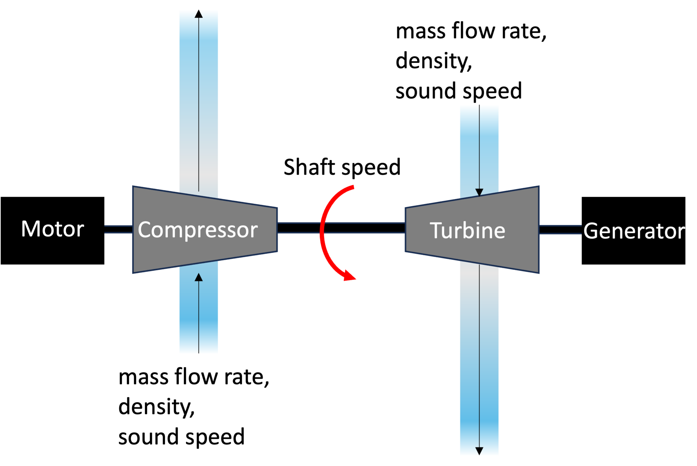
Figure 3: Compressor and turbine rated parameters
The shaft speed is smaller than the rated value. This difference is due to a margin between the rated value and the value imposed by the PID controller (presented in the next part). In a real system, the shaft speed should not be over the rated value, to avoid damage to the components.
[Components]
  [turbine]
    type = ShaftConnectedCompressor1Phase
    position = '${sec_x_pipe6} ${sec_y_pipe6} 0'
    inlet = 'sec_pipe5:out'
    outlet = 'sec_pipe6:in'
    A_ref = ${A_ref_turb}
    volume = ${V_turb}

    # A turbine is treated as an "inverse" compressor, this value determines if component is to be treated as turbine or compressor
    # If treat_as_turbine is omitted, code automatically assumes it is a compressor
    treat_as_turbine = true

    omega_rated = ${speed_rated}
    mdot_rated = ${rated_mfr}
    c0_rated = ${c0_rated_turb}
    rho0_rated = ${rho0_rated_turb}

    # Determines which compression ratio curve and efficiency curve to use depending on ratio of speed/rated_speed
    speeds = '0 0.5208 0.6250 0.7292 0.8333 0.9375'
    Rp_functions = 'rp_turb0 rp_turb1 rp_turb2 rp_turb3 rp_turb4 rp_turb5'
    eff_functions = 'eff_turb1 eff_turb1 eff_turb2 eff_turb3 eff_turb4 eff_turb5'

    min_pressure_ratio = 1.0

    speed_cr_I = 0
    inertia_const = ${I_turb}
    inertia_coeff = '${I_turb} 0 0 0'

    # assume no shaft friction
    speed_cr_fr = 0
    tau_fr_const = 0
    tau_fr_coeff = '0 0 0 0'

    initial_p = ${p_sec}
    initial_vel_x = ${vel_ini_sec}
    use_scalar_variables = false
  []
[]Generator
A generator is added on the same shaft as the turbine to produce electricity. The ShaftConnectedMotor component type is once again used. The generator torque is defined as follow:
C is defined to generate 2 MWe at the rated shaft speed:
This parameter is used in the Functions block by the generator_torque_fn. This one is used to define the torque of the generator in the component block. Note that a negative sign is present because energy is extracted.
[Components]
  [generator]
    type = ShaftConnectedMotor
    inertia = ${I_generator}
    torque = generator_torque_fn
  []
[]Motor
A motor component of ShaftConnectedMotor type is added and connected to the Shaft. Its behavior is defined by the Control and ControlLogic blocks (see below).
[Components]
  [motor]
    type = ShaftConnectedMotor
    inertia = ${I_motor}
    torque = 0 # controlled
  []
[]Recuperator
The recuperator includes two counter-current coolant channels (the hot_leg and cold_leg). A HeatStructureCylindrical component is added to couple these two channels, and two heat transfers are defined using the HeatTransferFromHeatStructure1Phase. Each of them couples a channel with the heat structure.
[Components]
  [cold_leg]
    type = FlowChannel1Phase
    position = '${sec_x_cold} ${sec_y_cold} 0'
    orientation = '0 -1 0'
    length = '${SEC_L_COLD}'
    n_elems = '${sec_n_elems_cold}'
    A = ${SEC_A_COLD}

    fp = air
    initial_p = ${p_sec}
    initial_vel = ${vel_ini_sec}
  []
[][Components]
[hot_leg]
type = FlowChannel1Phase
position = '${sec_x_hot} ${sec_y_hot} 0'
orientation = '0 1 0'
length = ${SEC_L_HOT}
n_elems = ${sec_n_elems_hot}
A = ${SEC_A_HOT}
fp = air
initial_T = ${T_ambient}
initial_p = ${p_ambient}
initial_vel = ${vel_ini_sec}
[]
[][Components]
[recuperator]
type = HeatStructureCylindrical
orientation = '0 -1 0'
position = '${sec_x_cold} ${sec_y_cold} 0'
length = '${SEC_L_COLD}'
widths = ${recuperator_width}
n_elems = '${sec_n_elems3}'
n_part_elems = 2
names = recuperator
solid_properties = steel
solid_properties_T_ref = '0' # This material is independent of temp.
inner_radius = '${fparse SEC_D1 / 2}'
offset_mesh_by_inner_radius = true
[]
[][Components]
[heat_transfer_cold_leg]
type = HeatTransferFromHeatStructure1Phase
flow_channel = cold_leg
hs = recuperator
hs_side = OUTER
[]
[][Components]
[heat_transfer_hot_leg]
type = HeatTransferFromHeatStructure1Phase
flow_channel = hot_leg
hs = recuperator
hs_side = INNER
[]
[]Controls
A ControlLogic block is added to control the motor torque.
The initial_motor_PID of type PIDControl defines the behavior of the motor at the beginning. It depends on the set_point block, whose type is a GetFunctionValueControl. It declares the desired shaft speed, which is the rated shaft speed minus 9000 rpm (see the turbine paragraph)
As the shaft speed and heat transfer from the core progressively increase, the turbine generates torque and the need for the motor torque becomes smaller. Thus, it progressively decreases, and it is eventually shut off.
A motor_PID, whose type is SetComponentRealValueControl, decides which value must be attributed to the motor torque. If the motor torque is too small, the motor is shut, using a motor_torque_fn_shutdown function written in the Functions block. Else, the behavior of the motor is still defined by the PIDControl. This condition is defined using the logic block, whose type is ParsedFunctionControl. In this one, a time condition is added: if the elapsed time is too small, the condition on the motor torque value is not applicable. At the beginning of the simulation: the motor torque is small and increasing, but it should not be shut.
[ControlLogic]

  # Sets desired shaft speed to be reached by motor NOTE: SHOULD BE SET LOWER THAN RATED TURBINE RPM
  [set_point]
    type = GetFunctionValueControl
    function = '${fparse speed_rated_rpm - 9000}'
  []

  # PID with gains determined by iterative process NOTE: Gain values are system specific
  [initial_motor_PID]
    type = PIDControl
    set_point = set_point:value
    input = shaft_RPM

    initial_value = ${motor_ini_val}
    K_p = ${motor_K_p}
    K_i = ${motor_K_i}
    K_d = ${motor_K_d}
  []

  # Determines when the PID system should be running and when it should begin the shutdown cycle. If needed: PID output, else: shutdown function
  [logic]
    type = ParsedFunctionControl
    function = 'if(time_simulation < 100, PID, if(motor > ${motor_shutdown_value}, PID, shutdown_fn))'
    symbol_names = 'time_simulation motor turb PID shutdown_fn'
    symbol_values = 'time_simulation sec_motor_torque turbine_torque initial_motor_PID:output sec_motor_torque_fn_shutdown'
  []

  # Takes the output generated in [logic] and applies it to the motor torque
  [motor_PID]
    type = SetComponentRealValueControl
    component = motor
    parameter = torque
    value = logic:value
  []
[]Startup and load follow transient
The model description above defines mainly the model used for the startup transient. In the case of the load follow transient, some blocks and parameters are disabled, because the system starts from the operating values computed in the startup transient. The following elements are commented:
the
initial_vel,initial_vel_x,initial_vel_y,initial_vel_z,initial_T,initial_pin the GlobalParams and in the various components where they were defined (pipes, junctions, etc.),the
is_tripped_fn,PID_tripped_constant_value,PID_tripped_status_fn,sec_motor_torque_fn_shutdownFunctions, which defined in the startup transient the motor behavior,the
time_trip_auxandPID_trip_status_auxAuxScalarKernels, which associated the previous functions results to thetime_tripandPID_trip_statusAuxVariables,the ControlLogic blocks that gave the retroaction on the motor behavior: the
set_point,initial_motor_PID,logicandmotor_PID,the Controls that are associated:
PID_trip_statusandtime_PID.
The AuxVariables defined to control the motor behavior are not disabled because the input file of the load follow transient needs to import data from the startup transient. To do so, some of the defined objects in the two input file, particularly the AuxVariables, need to be the same.
Two ControlLogic blocks are added to impose the core power during the load follow transient. A power_logic, whose type is ParsedFunctionControl, calls a power_fn function, which defines the power dependance on the time. It is then transferred to a power_applied sub block (of type SetComponentRealValueControl) which indicates to attribute this behavior to the total_power component block.
[ControlLogic]

  # Changes of power
  [power_logic]
    type = ParsedFunctionControl
    function = 'power_fn'
    symbol_names = 'power_fn'
    symbol_values = 'power_fn'
  []
  # Applies heat source to the total_power block
  [power_applied]
    type = SetComponentRealValueControl
    component = total_power
    parameter = power
    value = power_logic:value
  []
[]The data are transferred from the startup transient results to the load follow simulation using a supplemental output in the first input file. In the Outputs block, the checkpoint parameter is defined as true. The results saved in this output are then called in a Problem block in the load follow input file.
[Outputs]

  file_base = 'htgr_startup_transient'
  exodus = true
  [csv]
    type = CSV
    hide = 'core/core_heating:power_shape_fn:integral'
  []

  [cp]
    type = Checkpoint
    execute_on = 'FINAL'
  []

  [console]
    type = Console
    max_rows = 5
    show = 'core_T_in core_T_out core_p_difference core_m_dot_in core_power_difference
    hx_pri_T_in hx_pri_T_out  hx_pri_p_difference  hx_pri_power_difference
    pump_p_in pump_p_out pump_p_difference

    comp_T_in comp_T_out comp_p_in comp_p_out
    turb_T_in turb_T_out turb_p_in turb_p_out
    generator_power cycle_efficiency shaft_speed
    hx_sec_T_in hx_sec_T_out  hx_sec_p_in hx_sec_p_out hx_sec_p_difference hx_sec_m_dot_in
    hx_sec_m_dot_difference hx_sec_power_flux
    '
  []
[][Problem]
restart_file_base = htgr_startup_transient_cp/LATEST
# Component areas are set using initial conditions
allow_initial_conditions_with_restart = true
[](microreactors/gcmr/balance_of_plant/htgr_startup_transient.i)
# Generic gas cooled micro reactor balance of plant with open-air recuperated Brayton cycle
# This input file models a startup transient
# POC: Lise Charlot (lise.charlot at inl.gov)
# If using or referring to this model, please cite as explained in
# https://mooseframework.inl.gov/virtual_test_bed/citing.html
################################################################################################################
################ ******************** GOAL OF THIS SIMULATION ******************** ##################
################################################################################################################
# The following file simulates how a small HTGR coupled with a Brayton cycle reaches a steady state from an intial
# power equal to zero to a production of P_core = 15 MWth and P_generator = 2 MWe.
# The steady state reached during this simulation (stored using a checkpoint) can be used as a starting point for
# a load follow transient simulation, simulating a power modulation.
################################################################################################################
################ ******************** PRIMARY LOOP DESCRIPTION ******************** ##################
################################################################################################################
# The following components of the primary loop are included in this model:
#
# 1/ Core: Heat is provided by a prescribed power source in a cylindrical heat structure. A single channel is used for the fluid flow.
# 2/ Pressurizer: this component is added to maintain during the simulation a pressure which stays at 90 bar approximately.
# 3/ Heat exchanger: the primary fluid transfers through a heat structure its power to a secondary fluid.
# 4/ Pump
#
################################################################################################################
################ ******************** SECONDARY LOOP DESCRIPTION ******************** ##################
################################################################################################################
# The secondary loop is an open, recuperated Brayton cycle. A motor is used for startup.
# The motor torque is adjusted using a PID controller
#
# The transient is controlled as follows:
# * 0 - few seconds: Motor increases shaft speed to approx. 90,000 RPM by PID control
# * few seconds - end of the simulation: Torque supplied by turbine increases to steady state level
# as working fluid temperature increases. Torque supplied by
# the motor is ramped down to 0 N-m transitioning shaft control
# to the turbine at its rated speed of 95,000 RPM.
##################################################################
################ INITIAL PARAMETERS ####################
##################################################################
T_ini = 400 #K
vel_ini_pri = 0.00001 # m/s
vel_ini_sec = 0.00001 # m/s
vel_y_ini_default = 0.00001 # m/s
vel_z_ini_default = 0.00001 # m/s
pri_press = 9e6 # Pa
################################################################################################################
################ ******************** PRIMARY LOOP PARAMETERS ******************** ##################
################################################################################################################
##################################################################
################### CORE PARAMETERS #######################
##################################################################
# parameters of the coolant channels
core_radius_coolant = 0.00635 # m
core_length_channel = 2 # m
core_channel_n_elems = 50
# numbers of channels and assemblies
core_nb_assembly = 55
core_nb_coolant_per_assembly = 18
core_nb_fuel_per_assembly = 42
core_nb_coolant_tot = '${fparse core_nb_assembly * core_nb_coolant_per_assembly}'
# other parameters of the assembly
core_lattice_pitch = 0.022 # m optimal size of the lattice pitch to have a good burnup and a long life of the assembly for UN TRISO
core_radius_fuel = 0.00794 # m
# calculus of the equivalent parameters of a cylindrical heat structure around the coolant channel
core_section_assembly = '${fparse 3 * ( sqrt(3) / 2) * 5 * core_lattice_pitch * 5 * core_lattice_pitch}' # calculus of the assembly section (hexagonal) using the lattice pitch (1/5 of a side of the hexagon)
core_section_fuel_channel = '${fparse pi * core_radius_fuel * core_radius_fuel}'
core_section_mod_and_coolant = '${fparse core_section_assembly - ( core_nb_fuel_per_assembly * core_section_fuel_channel )}'
core_radius_equiv_mod = '${fparse sqrt( core_section_mod_and_coolant / ( pi * core_nb_coolant_per_assembly))}' # calculus of the radius of the moderator in an equivalent cylindrical heat structure around each coolant channel
core_radius_equiv_complete_hs = '${fparse sqrt( core_section_assembly / (pi * core_nb_coolant_per_assembly))}' # calculus of the radius of the complete equivalent cylindrical heat structure around each coolant channel
# power
tot_power = 15000000 # Wth
##################################################################
################### HX PARAMETERS #######################
##################################################################
# hx parameters
hx_dia_pri = 0.003 # m
hx_dia_sec = 0.005 # m
hx_wall_thickness = 0.001 # m
hx_length = 2 # m
hx_n_elems_axial = 10
hx_nb_channels = 20000
##################################################################
################### PIPES PARAMETERS #######################
##################################################################
pri_pipes_radius = 0.12 # m
pri_pipes_area = '${fparse pi * pri_pipes_radius * pri_pipes_radius}'
pri_pipes_D_h = '${fparse 2 * pi * pri_pipes_radius}'
pri_pipe1_n_elems = 3
pri_pipe2_n_elems = 10
pri_pipe3_n_elems = 10
pri_pipe4_n_elems = 10
pri_pipe5_n_elems = 3
pri_pipe6_n_elems = 20
pri_pipe_prz_n_elems = 10
PRI_L1 = 0.5 # m
PRI_L2 = 2. # m
PRI_L3 = 2. # m
PRI_L4 = 2. # m
PRI_L5 = ${PRI_L1}
PRI_L6 = 11. # m
PRI_L_prz = 2. # m
##################################################################
################### PUMP #######################
##################################################################
pump_area = '${fparse 1 * pri_pipes_area}'
pump_volume = 0.5 # m^3
pump_inertia_coeff = '1 1 1 1'
pump_inertia_const = 1.61397
pump_omega_rated = 5 # rad/s
pump_speed_cr_I = 1e12
pump_speed_cr_fr = 0
pump_torque_rated = 50 # Nm
pump_volumetric_rated = 2. # m^3/s
pump_head_rated = 350 # m
pump_tau_fr_coeff = '0 0 9.084 0'
pump_tau_fr_const = 0
pump_density_rated = 5 # kg/m^3
pri_motor_inertia = 2 # kg-m^2
pri_motor_torque = 50 # Nm
shaft_initial_speed = 2 # rad/s
##################################################################
################## GEOMETRICAL PARAMETERS ######################
##################################################################
#
#
# ^
# |
# |
# | PRESSURIZER
# | HX [SEC]
# | [...]<=============[...]
# (x0,y0) PIPE1 CORE PIPE2 | PIPE3 HX [PRI] PIPE4 PIPE5
# X--------------> =============> --------------> --------------> =============> --------------> [PUMP] -------------->
# <--------------------------------------------------------------------------------------------------------------------
# "PIPE6"
#
#
pri_x0 = 0. # m
pri_y0 = 0. # m
pri_x_pipe1 = ${pri_x0}
pri_x_core = '${fparse pri_x_pipe1 + PRI_L1}'
pri_x_pipe2 = '${fparse pri_x_core + core_length_channel}'
pri_x_pipe3 = '${fparse pri_x_pipe2 + PRI_L2}'
pri_x_hx = '${fparse pri_x_pipe3 + PRI_L3}'
pri_x_pipe4 = '${fparse pri_x_hx + hx_length}'
pri_x_pipe5 = '${fparse pri_x_pipe4 + PRI_L4}'
pri_x_pipe6 = '${fparse pri_x_pipe5 + PRI_L5}'
pri_y_pipe1 = ${pri_y0}
pri_y_core = ${pri_y_pipe1}
pri_y_pipe2 = ${pri_y_pipe1}
pri_y_pipe3 = ${pri_y_pipe1}
pri_y_hx = ${pri_y_pipe1}
pri_y_pipe4 = ${pri_y_pipe1}
pri_y_pipe5 = ${pri_y_pipe1}
pri_y_pipe6 = '${fparse pri_y_pipe1 - 0.1}'
################################################################################################################
################ ******************** SECONDARY LOOP PARAMETERS ******************** ##################
################################################################################################################
##################################################################
################ INITIAL PARAMETERS ####################
##################################################################
p_ambient = 1e5 # Pa
p_sec = 1e5 # Pa
T_ambient = 300 # K
##################################################################
############# MOTOR AND GENERATOR PARAMETERS #################
##################################################################
# parameter of the shutown decrease of the motor torque
motor_shutdown_value = 150.
motor_shutdown_time = 8000 # s
generator_torque_per_shaft_speed = -0.025
I_motor = 1.0
I_generator = 1.0
motor_ini_val = 50. # Nm
motor_K_p = 0.0085
motor_K_i = 0.00000007
motor_K_d = 0
##################################################################
################### PIPES PARAMETERS #######################
##################################################################
# diameters of the pipes
SEC_D1 = 0.35 # m
SEC_D2 = ${SEC_D1}
SEC_D_COLD = ${SEC_D1}
SEC_D3 = ${SEC_D1}
SEC_D4 = ${SEC_D1}
SEC_D5 = ${SEC_D1}
SEC_D6 = ${SEC_D1}
SEC_D_HOT = ${SEC_D1}
# sections of the pipes
SEC_A1 = '${fparse 0.25 * pi * SEC_D1^2}'
SEC_A2 = '${fparse 0.25 * pi * SEC_D2^2}'
SEC_A_COLD = '${fparse 0.25 * pi * SEC_D_COLD^2}'
SEC_A3 = '${fparse 0.25 * pi * SEC_D3^2}'
SEC_A4 = '${fparse 0.25 * pi * SEC_D4^2}'
SEC_A5 = '${fparse 0.25 * pi * SEC_D5^2}'
SEC_A6 = '${fparse 0.25 * pi * SEC_D6^2}'
SEC_A_HOT = '${fparse 0.25 * pi * SEC_D_HOT^2}'
recuperator_width = 0.005 #m
#length of the pipes
SEC_L1 = 5.0 # m
SEC_L2 = '${fparse SEC_L_HX / 2}'
SEC_L_COLD = ${SEC_L1}
SEC_L3 = ${SEC_L1}
SEC_L_HX = 2. # m
SEC_L4 = ${SEC_L1}
SEC_L5 = '${fparse SEC_L_HX / 2}'
SEC_L6 = '${fparse SEC_L5 + recuperator_width}'
SEC_L_HOT = ${SEC_L_COLD}
##################################################################
################### GEOMETRICAL PARAMETERS #######################
##################################################################
#
# PIPE1 PIPE2
# ------------------------>[COMP]-------------------------> ^
# (x0, y0) | |
# | |
# | |
# COLD LEG | | HOT LEG
# | |
# | |
# | |
# | |
# PIPE5 PIPE6 V |
# ----->[TURB]-----> |
# | |
# | |
# | |
# | |
# PIPE4 | | PIPE3
# | |
# | |
# | |
# | V
# <==================
# HX [SEC]
#
# [...]==================>[...]
# HX [PRI]
#
# x and y coordinates of the components
# starting point coordinates are computed so the hx_sec channel is located in the same place than the hx_pri channel
# /!\ because of the fact that hx_sec is in the opposite side than hx_pri, the x and y coordinates of hx_ sec are the same than those of pri_pipe4 and not hx_pri
sec_x0 = '${fparse - SEC_L1 - SEC_L2 + pri_x_pipe4}'
sec_y0 = '${fparse SEC_L3 + SEC_L_COLD + hx_wall_thickness}'
sec_x_pipe1 = ${sec_x0}
sec_x_pipe2 = '${fparse sec_x_pipe1 + SEC_L1}'
sec_x_cold = '${fparse sec_x_pipe2 + SEC_L2}'
sec_x_pipe3 = ${sec_x_cold}
sec_x_hx = ${sec_x_cold}
sec_x_pipe4 = '${fparse sec_x_hx - SEC_L_HX}'
sec_x_pipe5 = ${sec_x_pipe4}
sec_x_pipe6 = '${fparse sec_x_pipe5 + SEC_L5}'
sec_x_hot = '${fparse sec_x_pipe6 + SEC_L6}'
sec_y_pipe1 = ${sec_y0}
sec_y_pipe2 = ${sec_y_pipe1}
sec_y_cold = ${sec_y_pipe2}
sec_y_pipe3 = '${fparse sec_y_cold - SEC_L3 }'
sec_y_hx = '${fparse sec_y_pipe3 - SEC_L3 }'
sec_y_pipe4 = ${sec_y_hx}
sec_y_pipe5 = '${fparse sec_y_pipe4 + SEC_L4}'
sec_y_pipe6 = ${sec_y_pipe5}
sec_y_hot = ${sec_y_pipe6}
# x and y coordinates of some of the inlets/outlets of some components, used by postprocessors
sec_x_pipe1_out = '${fparse sec_x_pipe1 + SEC_L1 - 0.001}'
sec_x_pipe2_in = '${fparse sec_x_pipe2 + 0.001}'
sec_x_pipe5_out = '${fparse sec_x_pipe5 + SEC_L5 - 0.001}'
sec_x_pipe6_in = '${fparse sec_x_pipe6 + 0.1}' # the pressure difference is particularly high at the turbine outlet. The measure point is placed a bit far from the real outlet to have the exact outlet pressure.
sec_y_hot_in = '${fparse sec_y_hot + 0.001}'
sec_y_hot_out = '${fparse sec_y_hot + SEC_L_HOT - 0.001}'
hot_leg_in = ${sec_y_hot_in}
hot_leg_out = ${sec_y_hot_out}
cold_leg_in = '${fparse sec_y_cold - 0.001}'
cold_leg_out = '${fparse sec_y_cold - (SEC_L3) - 0.001}'
##################################################################
################### N_ELEMS PARAMETERS #######################
##################################################################
sec_n_elems1 = 5
sec_n_elems2 = ${sec_n_elems1}
sec_n_elems_cold = ${sec_n_elems1}
sec_n_elems3 = ${sec_n_elems1}
sec_n_elems4 = ${sec_n_elems1}
sec_n_elems5 = ${sec_n_elems1}
sec_n_elems6 = 20 # the number of elements is higher in order to have a more precise result of the pressure difference which is particularly deep with the turbine
sec_n_elems_hot = ${sec_n_elems_cold}
##################################################################
############### TURB AND COMPRESSOR PARAMETERS ###################
##################################################################
# geometrical parameters of the turb and compressor
A_ref_comp = '${fparse 1.5 * (SEC_A1 + SEC_A2)}'
V_comp = '${fparse A_ref_comp * 4.0}'
A_ref_turb = '${fparse 0.5 * (SEC_A5 + SEC_A6)}'
V_turb = '${fparse A_ref_turb * 4.0}'
#rated parameters of the turb and compressor
c0_rated_comp = 340. # m/s
rho0_rated_comp = 1.2 # kg/m^3
c0_rated_turb = 670 # m/s
rho0_rated_turb = 1.40 # kg/m^3
rated_mfr = 20 # ks/s
speed_rated_rpm = 95000 # rpm
speed_rated = '${fparse speed_rated_rpm * 2 * pi / 60.0}'
#other parameters
speed_initial = 0
I_comp = 1.0 # kg-m^2
I_turb = 1.0 # kg-m^2
eff_comp = 0.79
eff_turb = 0.843
[GlobalParams]
initial_vel_y = ${vel_y_ini_default}
initial_vel_z = ${vel_z_ini_default}
initial_T = ${T_ini}
closures = thm
scaling_factor_1phase = '1 1e-2 1e-5'
# gravity_vector = '0 0 0'
scaling_factor_rhoV = 1
scaling_factor_rhouV = 1e-2
scaling_factor_rhovV = 1e-2
scaling_factor_rhowV = 1e-2
scaling_factor_rhoEV = 1e-5
scaling_factor_temperature = 1e-2
rdg_slope_reconstruction = full
[]
[FluidProperties]
[he]
type = IdealGasFluidProperties
molar_mass = 4e-3
gamma = 1.67
k = 0.2556
mu = 3.22639e-5
[]
[air]
type = IdealGasFluidProperties
molar_mass = 29e-3
gamma = 1.4
k = 0.025 # W/(m.K)
mu = 1.8e-5 # Pa.s
[]
[]
[Closures]
[thm]
type = Closures1PhaseTHM
[]
[]
[SolidProperties]
[graphite]
type = ThermalFunctionSolidProperties
rho = 2160 # kg/m3
k = 40 # W/(m.K)
cp = 2100 # J/(kg.K) approximate mean specific heat of graphite between 800 K (coolant) and 1400 K (fuel)
[]
[fuel]
type = ThermalFunctionSolidProperties
rho = 10970 # kg/m3
k = 5 # W/(m.K)
cp = 300 # J/(kg.K)
[]
[steel]
type = ThermalFunctionSolidProperties
rho = 8050 # kg/m3
k = 45 # W/(m.K)
cp = 466 # J/(kg.K)
[]
[]
[Functions]
################################################################################################################
################ ******************** PRIMARY LOOP FUNCTIONS ******************** ##################
################################################################################################################
[head_fcn]
type = PiecewiseLinear
data_file = bingham_head_data.csv
format = columns
[]
[torque_fcn]
type = PiecewiseLinear
data_file = bingham_torque_data.csv
format = columns
[]
################################################################################################################
################ ******************** SECONDARY LOOP FUNCTIONS ******************** ##################
################################################################################################################
##########################
# Motor
##########################
# Functions for control logic that determines when to shut off the PID system
[is_tripped_fn]
type = ParsedFunction
symbol_names = 'sec_motor_torque'
symbol_values = 'sec_motor_torque'
expression = '${motor_shutdown_value} > sec_motor_torque'
[]
[PID_tripped_constant_value]
type = ConstantFunction
value = 1
[]
[PID_tripped_status_fn]
type = ParsedFunction
symbol_values = 'PID_trip_status'
symbol_names = 'PID_trip_status'
expression = 'PID_trip_status'
[]
[time_fn]
type = ParsedFunction
expression = t
[]
# Shutdown function which ramps down the motor once told by the control logic
[sec_motor_torque_fn_shutdown]
type = ParsedFunction
symbol_values = 'PID_trip_status time_trip'
symbol_names = 'PID_trip_status time_trip'
expression = 'if(PID_trip_status = 1, ${motor_shutdown_value} * exp( (time_trip - t)/${motor_shutdown_time}), 1)'
[]
# Generates motor power curve
[sec_motor_power_fn]
type = ParsedFunction
expression = 'torque * speed'
symbol_names = 'torque speed'
symbol_values = 'sec_motor_torque shaft:omega'
[]
##########################
# Generator
##########################
# Generates generator torque curve
[generator_torque_fn]
type = ParsedFunction
expression = 'slope * t'
symbol_names = 'slope'
symbol_values = '${generator_torque_per_shaft_speed}'
[]
# Generates generator power curve
[generator_power_fn]
type = ParsedFunction
expression = 'torque * speed'
symbol_names = 'torque speed'
symbol_values = 'generator_torque shaft:omega'
[]
##########################
# Compressor
##########################
# compressor pressure ratios
[rp_comp1]
type = PiecewiseLinear
data_file = 'rp_comp1.csv'
x_index_in_file = 0
y_index_in_file = 1
format = columns
extrap = true
[]
[rp_comp2]
type = PiecewiseLinear
data_file = 'rp_comp2.csv'
x_index_in_file = 0
y_index_in_file = 1
format = columns
extrap = true
[]
[rp_comp3]
type = PiecewiseLinear
data_file = 'rp_comp3.csv'
x_index_in_file = 0
y_index_in_file = 1
format = columns
extrap = true
[]
[rp_comp4]
type = PiecewiseLinear
data_file = 'rp_comp4.csv'
x_index_in_file = 0
y_index_in_file = 1
format = columns
extrap = true
[]
[rp_comp5]
type = PiecewiseLinear
data_file = 'rp_comp5.csv'
x_index_in_file = 0
y_index_in_file = 1
format = columns
extrap = true
[]
# compressor efficiencies
[eff_comp1]
type = ConstantFunction
value = ${eff_comp}
[]
[eff_comp2]
type = ConstantFunction
value = ${eff_comp}
[]
[eff_comp3]
type = ConstantFunction
value = ${eff_comp}
[]
[eff_comp4]
type = ConstantFunction
value = ${eff_comp}
[]
[eff_comp5]
type = ConstantFunction
value = ${eff_comp}
[]
##########################
# Turbine
##########################
# turbine pressure ratios
[rp_turb0]
type = ConstantFunction
value = 1
[]
[rp_turb1]
type = PiecewiseLinear
data_file = 'rp_turb1.csv'
x_index_in_file = 0
y_index_in_file = 1
format = columns
extrap = true
[]
[rp_turb2]
type = PiecewiseLinear
data_file = 'rp_turb2.csv'
x_index_in_file = 0
y_index_in_file = 1
format = columns
extrap = true
[]
[rp_turb3]
type = PiecewiseLinear
data_file = 'rp_turb3.csv'
x_index_in_file = 0
y_index_in_file = 1
format = columns
extrap = true
[]
[rp_turb4]
type = PiecewiseLinear
data_file = 'rp_turb4.csv'
x_index_in_file = 0
y_index_in_file = 1
format = columns
extrap = true
[]
[rp_turb5]
type = PiecewiseLinear
data_file = 'rp_turb5.csv'
x_index_in_file = 0
y_index_in_file = 1
format = columns
extrap = true
[]
# turbine efficiency
[eff_turb1]
type = ConstantFunction
value = ${eff_turb}
[]
[eff_turb2]
type = ConstantFunction
value = ${eff_turb}
[]
[eff_turb3]
type = ConstantFunction
value = ${eff_turb}
[]
[eff_turb4]
type = ConstantFunction
value = ${eff_turb}
[]
[eff_turb5]
type = ConstantFunction
value = ${eff_turb}
[]
[]
[Components]
################################################################################################################
################ ******************** PRIMARY LOOP COMPONENTS ******************** ##################
################################################################################################################
[total_power]
type = TotalPower
power = ${tot_power}
[]
[pri_pipe1]
type = FlowChannel1Phase
position = '${pri_x_pipe1} ${pri_y_pipe1} 0.'
orientation = '1 0 0'
length = ${PRI_L1}
n_elems = ${pri_pipe1_n_elems}
A = '${pri_pipes_area}'
D_h = '${pri_pipes_D_h}'
fp = he
initial_p = ${pri_press}
initial_vel = ${vel_ini_pri}
[]
[pri_jct_1_core]
type = JunctionParallelChannels1Phase
position = '${pri_x_core} ${pri_y_core} 0.'
connections = 'pri_pipe1:out core/coolant_channel:in'
volume = 1e-3
initial_p = ${pri_press}
initial_vel_x = ${vel_ini_pri}
use_scalar_variables=false
[]
[core]
[coolant_channel]
type = FlowChannel1Phase
position = '${pri_x_core} ${pri_y_core} 0.'
orientation = '1 0 0'
length = ${core_length_channel}
n_elems = ${core_channel_n_elems}
A = '${fparse pi * core_nb_coolant_tot * core_radius_coolant * core_radius_coolant}'
D_h = '${fparse 2 * core_radius_coolant}'
fp = he
initial_p = ${pri_press}
initial_vel = ${vel_ini_pri}
[]
[hs]
type = HeatStructureCylindrical
position = '${pri_x_core} ${pri_y_core} 0.'
orientation = '1 0 0'
length = ${core_length_channel}
n_elems = ${core_channel_n_elems}
inner_radius = ${core_radius_coolant}
num_rods = ${core_nb_coolant_tot}
initial_T = 400
names = 'graphite_layer fuel_layer'
widths = '${core_radius_equiv_mod} ${core_radius_equiv_complete_hs}'
solid_properties = 'graphite fuel'
solid_properties_T_ref = '0 0' # These materials are independent of temp.
n_part_elems = '3 3'
offset_mesh_by_inner_radius = true
[]
[core_heating]
type = HeatSourceFromTotalPower
hs = core/hs
regions = fuel_layer
power = total_power
[]
[core_ht]
type = HeatTransferFromHeatStructure1Phase
flow_channel = core/coolant_channel
hs = core/hs
hs_side = inner
P_hf = '${fparse pi * 2 * core_radius_coolant * core_nb_coolant_tot}'
[]
[]
[pri_jct_core_2]
type = JunctionParallelChannels1Phase
position = '${pri_x_pipe2} ${pri_y_pipe2} 0.'
connections = 'core/coolant_channel:out pri_pipe2:in'
volume = 1e-3
initial_p = ${pri_press}
initial_vel_x = ${vel_ini_pri}
use_scalar_variables=false
[]
[pri_pipe2]
type = FlowChannel1Phase
position = '${pri_x_pipe2} ${pri_y_pipe2} 0.'
orientation = '1 0 0'
length = ${PRI_L2}
n_elems = ${pri_pipe2_n_elems}
A = '${pri_pipes_area}'
D_h = '${pri_pipes_D_h}'
fp = he
initial_p = ${pri_press}
initial_vel = ${vel_ini_pri}
[]
[pressu]
[pri_jct_2_3_prz]
type = VolumeJunction1Phase
connections = 'pri_pipe2:out pri_pipe3:in pressu/pipe_prz:in'
position = '${pri_x_pipe3} ${pri_y_pipe3} 0.'
volume = 1e-3
initial_p = ${pri_press}
initial_vel_x = ${vel_ini_pri}
use_scalar_variables=false
[]
[pipe_prz]
type = FlowChannel1Phase
position = '${pri_x_pipe3} ${pri_y_pipe3} 0.'
orientation = '0 1 0'
length = ${PRI_L_prz}
n_elems = ${pri_pipe_prz_n_elems}
A = '${pri_pipes_area}'
D_h = '${pri_pipes_D_h}'
fp = he
initial_p = ${pri_press}
initial_vel = ${vel_ini_pri}
[]
[prz]
type = InletStagnationPressureTemperature1Phase
p0 = ${pri_press}
T0 = ${T_ini}
input = 'pressu/pipe_prz:out'
[]
[]
[pri_pipe3]
type = FlowChannel1Phase
position = '${pri_x_pipe3} ${pri_y_pipe3} 0.'
orientation = '1 0 0'
length = ${PRI_L3}
n_elems = ${pri_pipe3_n_elems}
A = '${pri_pipes_area}'
D_h = '${pri_pipes_D_h}'
fp = he
initial_p = ${pri_press}
initial_vel = ${vel_ini_pri}
[]
[pri_jct_3_hx_pri]
type = JunctionParallelChannels1Phase
position = '${pri_x_hx} ${pri_y_hx} 0.'
connections = 'pri_pipe3:out hx/pri:in'
volume = 1e-3
initial_p = ${pri_press}
initial_vel_x = ${vel_ini_pri}
use_scalar_variables=false
[]
[hx]
[pri]
type = FlowChannel1Phase
position = '${pri_x_hx} ${pri_y_hx} 0.'
orientation = '1 0 0'
length = ${hx_length}
n_elems = ${hx_n_elems_axial}
A = '${fparse pi * hx_nb_channels * hx_dia_pri * hx_dia_pri * 0.25}'
D_h = ${hx_dia_pri}
fp = he
initial_p = ${pri_press}
initial_vel = ${vel_ini_pri}
[]
[ht_pri]
type = HeatTransferFromHeatStructure1Phase
hs = hx/wall
hs_side = inner
flow_channel = hx/pri
P_hf = '${fparse pi * hx_nb_channels * hx_dia_pri}'
[]
[wall]
type = HeatStructureCylindrical
length = ${hx_length}
n_elems = ${hx_n_elems_axial}
n_part_elems = 1
names = 'hx_wall'
orientation = '1 0 0'
position = '${pri_x_hx} ${pri_y_hx} 0.'
widths = '${hx_wall_thickness}'
solid_properties = 'steel'
solid_properties_T_ref = '0' # This material is independent of temp.
inner_radius = '${fparse hx_dia_pri / 2}'
num_rods = ${hx_nb_channels}
[]
[ht_sec]
type = HeatTransferFromHeatStructure1Phase
hs = hx/wall
hs_side = outer
flow_channel = hx/sec
P_hf = '${fparse pi * hx_nb_channels * hx_dia_sec}'
[]
[sec]
type = FlowChannel1Phase
position = '${sec_x_hx} ${sec_y_hx} 0.'
orientation = '-1 0 0'
length = ${hx_length}
n_elems = ${hx_n_elems_axial}
A = '${fparse pi * hx_nb_channels * hx_dia_sec * hx_dia_sec * 0.25}'
D_h = '${hx_dia_sec}'
fp = air
initial_p = ${p_sec}
initial_vel = ${vel_ini_sec}
[]
[]
[pri_jct_hx_pri_4]
type = JunctionParallelChannels1Phase
position = '${pri_x_pipe4} ${pri_y_pipe4} 0.'
connections = 'hx/pri:out pri_pipe4:in'
volume = 1e-3
initial_p = ${pri_press}
initial_vel_x = ${vel_ini_pri}
use_scalar_variables=false
[]
[pri_pipe4]
type = FlowChannel1Phase
position = '${pri_x_pipe4} ${pri_y_pipe4} 0.'
orientation = '1 0 0'
length = ${PRI_L4}
n_elems = ${pri_pipe4_n_elems}
A = '${pri_pipes_area}'
D_h = '${pri_pipes_D_h}'
fp = he
initial_p = ${pri_press}
initial_vel = ${vel_ini_pri}
[]
[circ]
[pump]
type = ShaftConnectedPump1Phase
inlet = 'pri_pipe4:out'
outlet = 'pri_pipe5:in'
position = '${pri_x_pipe5} ${pri_y_pipe5} 0.'
A_ref = ${pump_area}
scaling_factor_rhoEV = 1e-5
volume = ${pump_volume}
inertia_coeff = ${pump_inertia_coeff}
inertia_const = ${pump_inertia_const}
omega_rated = ${pump_omega_rated}
speed_cr_I = ${pump_speed_cr_I}
speed_cr_fr = ${pump_speed_cr_fr}
torque_rated = ${pump_torque_rated}
volumetric_rated = ${pump_volumetric_rated}
head_rated = ${pump_head_rated}
tau_fr_coeff = ${pump_tau_fr_coeff}
tau_fr_const = ${pump_tau_fr_const}
head = head_fcn
torque_hydraulic = torque_fcn
density_rated = ${pump_density_rated}
initial_p = ${pri_press}
initial_vel_x = ${vel_ini_pri}
use_scalar_variables=false
[]
[motor]
type = ShaftConnectedMotor
inertia = ${pri_motor_inertia}
torque = ${pri_motor_torque}
[]
[shaft]
type = Shaft
connected_components = 'circ/motor circ/pump'
initial_speed = ${shaft_initial_speed}
[]
[]
[pri_pipe5]
type = FlowChannel1Phase
position = '${pri_x_pipe5} ${pri_y_pipe5} 0.'
orientation = '1 0 0'
length = ${PRI_L5}
n_elems = ${pri_pipe5_n_elems}
A = '${pri_pipes_area}'
D_h = '${pri_pipes_D_h}'
fp = he
initial_p = ${pri_press}
initial_vel = ${vel_ini_pri}
[]
[pri_jct_5_6]
type = JunctionOneToOne1Phase
connections = 'pri_pipe5:out pri_pipe6:in'
[]
[pri_pipe6]
type = FlowChannel1Phase
position = '${pri_x_pipe6} ${pri_y_pipe6} 0.'
orientation = '-1 0 0'
length = ${PRI_L6}
n_elems = ${pri_pipe6_n_elems}
A = '${pri_pipes_area}'
D_h = '${pri_pipes_D_h}'
fp = he
initial_p = ${pri_press}
initial_vel = ${vel_ini_pri}
[]
[pri_jct_6_1]
type = JunctionOneToOne1Phase
connections = 'pri_pipe6:out pri_pipe1:in'
[]
################################################################################################################
################ ******************** SECONDARY LOOP COMPONENTS ******************** ##################
################################################################################################################
# system inlet pulling air from the open atmosphere
[inlet]
type = InletStagnationPressureTemperature1Phase
input = 'sec_pipe1:in'
p0 = ${p_ambient}
T0 = ${T_ambient}
[]
# Inlet pipe
[sec_pipe1]
type = FlowChannel1Phase
position = '${sec_x_pipe1} ${sec_y_pipe1} 0'
orientation = '1 0 0'
length = ${SEC_L1}
n_elems = ${sec_n_elems1}
A = ${SEC_A1}
fp = air
initial_T = ${T_ambient}
initial_p = ${p_ambient}
initial_vel = ${vel_ini_sec}
[]
# Compressor as defined in MAGNET PCU document (Guillen 2020)
[compressor]
type = ShaftConnectedCompressor1Phase
position = '${sec_x_pipe2} ${sec_y_pipe2} 0'
inlet = 'sec_pipe1:out'
outlet = 'sec_pipe2:in'
A_ref = ${A_ref_comp}
volume = ${V_comp}
omega_rated = ${speed_rated}
mdot_rated = ${rated_mfr}
c0_rated = ${c0_rated_comp}
rho0_rated = ${rho0_rated_comp}
# Determines which compression ratio curve and efficiency curve to use depending on ratio of speed/rated_speed
speeds = '0.5208 0.6250 0.7292 0.8333 0.9375'
Rp_functions = 'rp_comp1 rp_comp2 rp_comp3 rp_comp4 rp_comp5'
eff_functions = 'eff_comp1 eff_comp2 eff_comp3 eff_comp4 eff_comp5'
min_pressure_ratio = 1.0
speed_cr_I = 0
inertia_const = ${I_comp}
inertia_coeff = '${I_comp} 0 0 0'
# assume no shaft friction
speed_cr_fr = 0
tau_fr_const = 0
tau_fr_coeff = '0 0 0 0'
initial_p = ${p_sec}
initial_vel_x = ${vel_ini_sec}
use_scalar_variables=false
[]
# Outlet pipe from the compressor
[sec_pipe2]
type = FlowChannel1Phase
position = '${sec_x_pipe2} ${sec_y_pipe2} 0'
orientation = '1 0 0'
length = ${SEC_L2}
n_elems = ${sec_n_elems2}
A = ${SEC_A2}
fp = air
initial_p = ${p_sec}
initial_vel = ${vel_ini_sec}
[]
# 90 degree connection between pipe 2 and 3
[sec_jct_2_cold]
type = JunctionOneToOne1Phase
connections = 'sec_pipe2:out cold_leg:in'
[]
# Cold leg of the recuperator
[cold_leg]
type = FlowChannel1Phase
position = '${sec_x_cold} ${sec_y_cold} 0'
orientation = '0 -1 0'
length = '${SEC_L_COLD}'
n_elems = '${sec_n_elems_cold}'
A = ${SEC_A_COLD}
fp = air
initial_p = ${p_sec}
initial_vel = ${vel_ini_sec}
[]
# Recuperator which transfers heat from exhaust gas to heat_exchanger inlet gas to improve thermal efficency
[recuperator]
type = HeatStructureCylindrical
orientation = '0 -1 0'
position = '${sec_x_cold} ${sec_y_cold} 0'
length = '${SEC_L_COLD}'
widths = ${recuperator_width}
n_elems = '${sec_n_elems3}'
n_part_elems = 2
names = recuperator
solid_properties = steel
solid_properties_T_ref='0' # This material is independent of temp.
inner_radius = '${fparse SEC_D1 / 2}'
offset_mesh_by_inner_radius = true
[]
# heat transfer from recuperator to cold leg
[heat_transfer_cold_leg]
type = HeatTransferFromHeatStructure1Phase
flow_channel = cold_leg
hs = recuperator
hs_side = OUTER
[]
# heat transfer from hot leg to recuperator
[heat_transfer_hot_leg]
type = HeatTransferFromHeatStructure1Phase
flow_channel = hot_leg
hs = recuperator
hs_side = INNER
[]
[sec_jct_cold_3]
type = JunctionOneToOne1Phase
connections = 'cold_leg:out sec_pipe3:in'
[]
[sec_pipe3]
type = FlowChannel1Phase
position = '${sec_x_pipe3} ${sec_y_pipe3} 0'
orientation = '0 -1 0'
length = '${fparse SEC_L3}'
n_elems = '${fparse sec_n_elems3}'
A = ${SEC_A3}
fp = air
initial_p = ${p_sec}
initial_vel = ${vel_ini_sec}
[]
# 90 degree connection between pipe 3 and hx sec
[sec_jct_3_hx]
type = JunctionOneToOne1Phase
connections = 'sec_pipe3:out hx/sec:in'
[]
#############################
#### NB: hx/sec in the hx block, with the primary components
#############################
# 90 degree connection between hx sec and pipe 4
[sec_jct_hx_4]
type = JunctionOneToOne1Phase
connections = 'hx/sec:out sec_pipe4:in'
[]
# Pipe carrying hot gas back to the PCU
[sec_pipe4]
type = FlowChannel1Phase
position = '${sec_x_pipe4} ${sec_y_pipe4} 0'
orientation = '0 1 0'
length = ${SEC_L4}
n_elems = ${sec_n_elems4}
A = ${SEC_A4}
fp = air
initial_p = ${p_sec}
initial_vel = ${vel_ini_sec}
[]
# 90 degree connection between pipe 4 and 5
[sec_jct_4_5]
type = JunctionOneToOne1Phase
connections = 'sec_pipe4:out sec_pipe5:in'
[]
# Inlet pipe to the turbine
[sec_pipe5]
type = FlowChannel1Phase
position = '${sec_x_pipe5} ${sec_y_pipe5} 0'
orientation = '1 0 0'
length = ${SEC_L5}
n_elems = ${sec_n_elems5}
A = ${SEC_A5}
fp = air
initial_p = ${p_sec}
initial_vel = ${vel_ini_sec}
[]
# Turbine as defined in MAGNET PCU document (Guillen 2020) and (Wright 2006)
[turbine]
type = ShaftConnectedCompressor1Phase
position = '${sec_x_pipe6} ${sec_y_pipe6} 0'
inlet = 'sec_pipe5:out'
outlet = 'sec_pipe6:in'
A_ref = ${A_ref_turb}
volume = ${V_turb}
# A turbine is treated as an "inverse" compressor, this value determines if component is to be treated as turbine or compressor
# If treat_as_turbine is omitted, code automatically assumes it is a compressor
treat_as_turbine = true
omega_rated = ${speed_rated}
mdot_rated = ${rated_mfr}
c0_rated = ${c0_rated_turb}
rho0_rated = ${rho0_rated_turb}
# Determines which compression ratio curve and efficiency curve to use depending on ratio of speed/rated_speed
speeds = '0 0.5208 0.6250 0.7292 0.8333 0.9375'
Rp_functions = 'rp_turb0 rp_turb1 rp_turb2 rp_turb3 rp_turb4 rp_turb5'
eff_functions = 'eff_turb1 eff_turb1 eff_turb2 eff_turb3 eff_turb4 eff_turb5'
min_pressure_ratio = 1.0
speed_cr_I = 0
inertia_const = ${I_turb}
inertia_coeff = '${I_turb} 0 0 0'
# assume no shaft friction
speed_cr_fr = 0
tau_fr_const = 0
tau_fr_coeff = '0 0 0 0'
initial_p = ${p_sec}
initial_vel_x = ${vel_ini_sec}
use_scalar_variables=false
[]
# Outlet pipe from turbine
[sec_pipe6]
type = FlowChannel1Phase
position = '${sec_x_pipe6} ${sec_y_pipe6} 0'
orientation = '1 0 0'
length = ${SEC_L6}
n_elems = ${sec_n_elems6}
A = ${SEC_A6}
fp = air
initial_p = ${p_sec}
initial_vel = ${vel_ini_sec}
[]
# 90 degree connection between pipe 6 and hot leg
[sec_jct_6_hot]
type = JunctionOneToOne1Phase
connections = 'sec_pipe6:out hot_leg:in'
[]
# Hot leg of the recuperator
[hot_leg]
type = FlowChannel1Phase
position = '${sec_x_hot} ${sec_y_hot} 0'
orientation = '0 1 0'
length = ${SEC_L_HOT}
n_elems = ${sec_n_elems_hot}
A = ${SEC_A_HOT}
fp = air
initial_T = ${T_ambient}
initial_p = ${p_ambient}
initial_vel = ${vel_ini_sec}
[]
# System outlet dumping exhaust gas to the atmosphere
[outlet]
type = Outlet1Phase
input = 'hot_leg:out'
p = ${p_ambient}
[]
# Roatating shaft connecting motor, compressor, turbine, and generator
[shaft]
type = Shaft
connected_components = 'motor compressor turbine generator'
initial_speed = ${speed_initial}
[]
# 3-Phase electircal motor used for system start-up, controlled by PID
[motor]
type = ShaftConnectedMotor
inertia = ${I_motor}
torque = 0 # controlled
[]
# Electric generator supplying power to the grid
[generator]
type = ShaftConnectedMotor
inertia = ${I_generator}
torque = generator_torque_fn
[]
[]
[Postprocessors]
################################################################################################################
################ ******************** PRIMARY LOOP POSTPROCESSORS ******************** ##################
################################################################################################################
#####################################################
###### core ######
#####################################################
###### pressure
[core_p_in]
type = SideAverageValue
boundary = pri_jct_1_core
variable = p
execute_on = 'INITIAL TIMESTEP_END'
[]
[core_p_out]
type = SideAverageValue
boundary = pri_jct_core_2
variable = p
execute_on = 'INITIAL TIMESTEP_END'
[]
[core_p_difference]
type = DifferencePostprocessor
value1 = core_p_out
value2 = core_p_in
execute_on = 'INITIAL TIMESTEP_END'
[]
###### m_dot
[core_m_dot_in]
type = ADFlowJunctionFlux1Phase
boundary = core/coolant_channel:in
equation = mass
junction = pri_jct_1_core
connection_index = 1
execute_on = 'INITIAL TIMESTEP_END'
[]
[core_m_dot_out]
type = ADFlowJunctionFlux1Phase
boundary = core/coolant_channel:out
equation = mass
junction = pri_jct_core_2
connection_index = 0
execute_on = 'INITIAL TIMESTEP_END'
[]
[core_m_dot_difference]
type = DifferencePostprocessor
value1 = core_m_dot_out
value2 = core_m_dot_in
execute_on = 'INITIAL TIMESTEP_END'
[]
###### power
[core_power_flux]
type = ADHeatRateConvection1Phase
P_hf = '${fparse 2 * pi * core_nb_coolant_tot * core_radius_coolant}'
block = core/coolant_channel
execute_on = 'INITIAL TIMESTEP_END'
[]
[core_power_in]
type = ADFlowJunctionFlux1Phase
boundary = core/coolant_channel:in
equation = energy
junction = pri_jct_1_core
connection_index = 1
execute_on = 'INITIAL TIMESTEP_END'
[]
[core_power_out]
type = ADFlowJunctionFlux1Phase
boundary = core/coolant_channel:out
equation = energy
junction = pri_jct_core_2
connection_index = 0
execute_on = 'INITIAL TIMESTEP_END'
[]
[core_power_difference]
type = DifferencePostprocessor
value1 = core_power_out
value2 = core_power_in
execute_on = 'INITIAL TIMESTEP_END'
[]
###### T
[core_T_in]
type = SideAverageValue
boundary = pri_jct_1_core
variable = T
execute_on = 'INITIAL TIMESTEP_END'
[]
[core_T_out]
type = SideAverageValue
boundary = pri_jct_core_2
variable = T
execute_on = 'INITIAL TIMESTEP_END'
[]
[core_T_difference]
type = DifferencePostprocessor
value1 = core_T_out
value2 = core_T_in
execute_on = 'INITIAL TIMESTEP_END'
[]
###### T_wall
[core_T_wall_in]
type = SideAverageValue
boundary = core/coolant_channel:in
variable = T_wall
execute_on = 'INITIAL TIMESTEP_END'
[]
[core_T_wall_out]
type = SideAverageValue
boundary = core/coolant_channel:out
variable = T_wall
execute_on = 'INITIAL TIMESTEP_END'
[]
[core_T_wall_difference]
type = DifferencePostprocessor
value1 = core_T_wall_out
value2 = core_T_wall_in
execute_on = 'INITIAL TIMESTEP_END'
[]
#####################################################
###### heat_exchanger ######
#####################################################
################### primary loop ####################
###### pressure
[hx_pri_p_in]
type = SideAverageValue
boundary = pri_jct_3_hx_pri
variable = p
execute_on = 'INITIAL TIMESTEP_END'
[]
[hx_pri_p_out]
type = SideAverageValue
boundary = pri_jct_hx_pri_4
variable = p
execute_on = 'INITIAL TIMESTEP_END'
[]
[hx_pri_p_difference]
type = DifferencePostprocessor
value1 = hx_pri_p_out
value2 = hx_pri_p_in
execute_on = 'INITIAL TIMESTEP_END'
[]
###### m_dot
[hx_pri_m_dot_in]
type = ADFlowJunctionFlux1Phase
boundary = hx/pri:in
equation = mass
junction = pri_jct_3_hx_pri
connection_index = 1
execute_on = 'INITIAL TIMESTEP_END'
[]
[hx_pri_m_dot_out]
type = ADFlowJunctionFlux1Phase
boundary = hx/pri:out
equation = mass
junction = pri_jct_hx_pri_4
connection_index = 0
execute_on = 'INITIAL TIMESTEP_END'
[]
[hx_pri_m_dot_difference]
type = DifferencePostprocessor
value1 = hx_pri_m_dot_out
value2 = hx_pri_m_dot_in
execute_on = 'INITIAL TIMESTEP_END'
[]
###### temperature
[hx_pri_T_in]
type = SideAverageValue
boundary = pri_jct_3_hx_pri
variable = T
execute_on = 'INITIAL TIMESTEP_END'
[]
[hx_pri_T_out]
type = SideAverageValue
boundary = pri_jct_hx_pri_4
variable = T
execute_on = 'INITIAL TIMESTEP_END'
[]
[hx_pri_T_difference]
type = DifferencePostprocessor
value1 = hx_pri_T_out
value2 = hx_pri_T_in
execute_on = 'INITIAL TIMESTEP_END'
[]
###### energy
[hx_pri_power_in]
type = ADFlowJunctionFlux1Phase
boundary = hx/pri:in
equation = energy
junction = pri_jct_3_hx_pri
connection_index = 1
execute_on = 'INITIAL TIMESTEP_END'
[]
[hx_pri_power_out]
type = ADFlowJunctionFlux1Phase
boundary = hx/pri:out
equation = energy
junction = pri_jct_hx_pri_4
connection_index = 0
execute_on = 'INITIAL TIMESTEP_END'
[]
[hx_pri_power_difference]
type = DifferencePostprocessor
value1 = hx_pri_power_out
value2 = hx_pri_power_in
execute_on = 'INITIAL TIMESTEP_END'
[]
[hx_pri_power_flux]
type = ADHeatRateConvection1Phase
P_hf = '${fparse hx_nb_channels * pi * hx_dia_pri}'
block = hx/pri
execute_on = 'INITIAL TIMESTEP_END'
[]
#####################################################
###### pump ######
#####################################################
###### pressure
[pump_p_in]
type = SideAverageValue
boundary = pri_pipe4:out
variable = p
execute_on = 'INITIAL TIMESTEP_END'
[]
[pump_p_out]
type = SideAverageValue
boundary = pri_pipe5:in
variable = p
execute_on = 'INITIAL TIMESTEP_END'
[]
[pump_p_difference]
type = DifferencePostprocessor
value1 = pump_p_out
value2 = pump_p_in
execute_on = 'INITIAL TIMESTEP_END'
[]
###### temperature
[pump_T_in]
type = SideAverageValue
boundary = pri_pipe4:out
variable = T
execute_on = 'INITIAL TIMESTEP_END'
[]
[pump_T_out]
type = SideAverageValue
boundary = pri_pipe5:in
variable = T
execute_on = 'INITIAL TIMESTEP_END'
[]
[pump_T_difference]
type = DifferencePostprocessor
value1 = pump_T_out
value2 = pump_T_in
execute_on = 'INITIAL TIMESTEP_END'
[]
################################################################################################################
################ ******************** SECONDARY LOOP POSTPROCESSORS ******************** ##################
################################################################################################################
[time_simulation]
type = TimePostprocessor
[]
# Indicates when tau_turbine > tau_motor
[trip_time]
type = ScalarVariable
variable = time_trip
execute_on = 'TIMESTEP_END'
[]
##########################
# Motor
##########################
[sec_motor_torque]
type = RealComponentParameterValuePostprocessor
component = motor
parameter = torque
execute_on = 'INITIAL TIMESTEP_END'
[]
[sec_motor_power]
type = FunctionValuePostprocessor
function = sec_motor_power_fn
execute_on = 'INITIAL TIMESTEP_END'
[]
##########################
# generator
##########################
[generator_torque]
type = ShaftConnectedComponentPostprocessor
quantity = torque
shaft_connected_component_uo = generator:shaftconnected_uo
execute_on = 'INITIAL TIMESTEP_END'
[]
[generator_power]
type = FunctionValuePostprocessor
function = generator_power_fn
execute_on = 'INITIAL TIMESTEP_END'
[]
[cycle_efficiency]
type = ParsedPostprocessor
pp_names = 'generator_power core_power_flux'
expression = 'generator_power / core_power_flux'
execute_on = 'INITIAL TIMESTEP_END'
[]
##########################
# Shaft
##########################
# Speed in rad/s
[shaft_speed]
type = ScalarVariable
variable = 'shaft:omega'
execute_on = 'INITIAL TIMESTEP_END'
[]
# speed in RPM
[shaft_RPM]
type = ParsedPostprocessor
pp_names = 'shaft_speed'
expression = '(shaft_speed * 60) /( 2 * ${fparse pi})'
execute_on = 'INITIAL TIMESTEP_END'
[]
##########################
# Compressor
##########################
###### Torques
[comp_dissipation_torque]
type = ElementIntegralVariablePostprocessor
variable = 'dissipation_torque'
execute_on = 'INITIAL TIMESTEP_END'
block='compressor'
[]
[comp_isentropic_torque]
type = ElementIntegralVariablePostprocessor
variable = 'isentropic_torque'
execute_on = 'INITIAL TIMESTEP_END'
block='compressor'
[]
[comp_friction_torque]
type = ElementIntegralVariablePostprocessor
variable = 'friction_torque'
execute_on = 'INITIAL TIMESTEP_END'
block='compressor'
[]
[compressor_torque]
type = ParsedPostprocessor
pp_names = 'comp_dissipation_torque comp_isentropic_torque comp_friction_torque'
expression = 'comp_dissipation_torque + comp_isentropic_torque + comp_friction_torque'
[]
###### Pressure
[comp_p_in]
type = PointValue
variable = p
point = '${sec_x_pipe1_out} ${sec_y_pipe1} 0'
execute_on = 'INITIAL TIMESTEP_END'
[]
[comp_p_out]
type = PointValue
variable = p
point = '${sec_x_pipe2_in} ${sec_y_pipe2} 0'
execute_on = 'INITIAL TIMESTEP_END'
[]
[comp_p_ratio]
type = ParsedPostprocessor
pp_names = 'comp_p_in comp_p_out'
expression = 'comp_p_out / comp_p_in'
execute_on = 'INITIAL TIMESTEP_END'
[]
###### Temperature
[comp_T_in]
type = PointValue
variable = T
point = '${sec_x_pipe1_out} ${sec_y_pipe1} 0'
execute_on = 'INITIAL TIMESTEP_END'
[]
[comp_T_out]
type = PointValue
variable = T
point = '${sec_x_pipe2_in} ${sec_y_pipe2} 0'
execute_on = 'INITIAL TIMESTEP_END'
[]
[comp_T_ratio]
type = ParsedPostprocessor
pp_names = 'comp_T_in comp_T_out'
expression = '(comp_T_out - comp_T_in) / comp_T_out'
execute_on = 'INITIAL TIMESTEP_END'
[]
###### mass flow rate
[comp_m_dot]
type = ADFlowJunctionFlux1Phase
boundary = sec_pipe1:out
connection_index = 0
equation = mass
junction = compressor
[]
##########################
# Heat exchanger
##########################
######### temperature
[hx_sec_T_in]
type = SideAverageValue
boundary = sec_jct_3_hx
variable = T
[]
[hx_sec_T_out]
type = SideAverageValue
boundary = sec_jct_hx_4
variable = T
[]
[hx_sec_T_difference]
type = DifferencePostprocessor
value1 = hx_sec_T_out
value2 = hx_sec_T_in
[]
######### pressure
[hx_sec_p_in]
type = SideAverageValue
boundary = sec_jct_3_hx
variable = p
[]
[hx_sec_p_out]
type = SideAverageValue
boundary = sec_jct_hx_4
variable = p
[]
[hx_sec_p_difference]
type = DifferencePostprocessor
value1 = hx_sec_p_out
value2 = hx_sec_p_in
[]
######### flow rate
[hx_sec_m_dot_in]
type = ADFlowJunctionFlux1Phase
boundary = hx/sec:in
connection_index = 1
equation = mass
junction = sec_jct_3_hx
[]
[hx_sec_m_dot_out]
type = ADFlowJunctionFlux1Phase
boundary = hx/sec:out
connection_index = 0
equation = mass
junction = sec_jct_hx_4
[]
[hx_sec_m_dot_difference]
type = DifferencePostprocessor
value1 = hx_sec_m_dot_out
value2 = hx_sec_m_dot_in
[]
######### power
[hx_sec_power_in]
type = ADFlowJunctionFlux1Phase
boundary = hx/sec:in
connection_index = 1
equation = energy
junction = sec_jct_3_hx
[]
[hx_sec_power_out]
type = ADFlowJunctionFlux1Phase
boundary = hx/sec:out
connection_index = 0
equation = energy
junction = sec_jct_hx_4
[]
[hx_sec_power_difference]
type = DifferencePostprocessor
value1 = hx_sec_power_out
value2 = hx_sec_power_in
[]
[hx_sec_power_flux]
type = ADHeatRateConvection1Phase
P_hf = '${fparse pi * hx_dia_sec * hx_nb_channels }'
block = hx/sec
[]
##########################
# turbine
##########################
###### Torques
[turb_dissipation_torque]
type = ElementIntegralVariablePostprocessor
variable = 'dissipation_torque'
execute_on = 'INITIAL TIMESTEP_END'
block='turbine'
[]
[turb_isentropic_torque]
type = ElementIntegralVariablePostprocessor
variable = 'isentropic_torque'
execute_on = 'INITIAL TIMESTEP_END'
block='turbine'
[]
[turb_friction_torque]
type = ElementIntegralVariablePostprocessor
variable = 'friction_torque'
execute_on = 'INITIAL TIMESTEP_END'
block='turbine'
[]
[turbine_torque]
type = ParsedPostprocessor
pp_names = 'turb_dissipation_torque turb_isentropic_torque turb_friction_torque'
expression = 'turb_dissipation_torque + turb_isentropic_torque + turb_friction_torque'
[]
###### Pressure
[turb_p_in]
type = PointValue
variable = p
point = '${sec_x_pipe5_out} ${sec_y_pipe5} 0'
execute_on = 'INITIAL TIMESTEP_END'
[]
[turb_p_out]
type = PointValue
variable = p
point = '${sec_x_pipe6_in} ${sec_y_pipe6} 0'
execute_on = 'INITIAL TIMESTEP_END'
[]
[turb_p_ratio]
type = ParsedPostprocessor
pp_names = 'turb_p_in turb_p_out'
expression = 'turb_p_in / turb_p_out'
execute_on = 'INITIAL TIMESTEP_END'
[]
###### Temperature
[turb_T_in]
type = PointValue
variable = T
point = '${sec_x_pipe5_out} ${sec_y_pipe5} 0'
execute_on = 'INITIAL TIMESTEP_END'
[]
[turb_T_out]
type = PointValue
variable = T
point = '${sec_x_pipe6_in} ${sec_y_pipe6} 0'
execute_on = 'INITIAL TIMESTEP_END'
[]
###### mass flow rate
[turb_m_dot]
type = ADFlowJunctionFlux1Phase
boundary = sec_pipe5:out
connection_index = 0
equation = mass
junction = turbine
[]
##########################
# Recuperator
##########################
###### Temperatures cold leg
[cold_leg_T_in]
type = PointValue
variable = T
point = '${sec_x_cold} ${cold_leg_in} 0'
execute_on = 'INITIAL TIMESTEP_END'
[]
[cold_leg_T_out]
type = PointValue
variable = T
point = '${sec_x_cold} ${cold_leg_out} 0'
execute_on = 'INITIAL TIMESTEP_END'
[]
###### Temperatures hot leg
[hot_leg_T_in]
type = PointValue
variable = T
point = '${sec_x_hot} ${hot_leg_in} 0'
execute_on = 'INITIAL TIMESTEP_END'
[]
[hot_leg_T_out]
type = PointValue
variable = T
point = '${sec_x_hot} ${hot_leg_out} 0'
execute_on = 'INITIAL TIMESTEP_END'
[]
###### Pressure cold leg
[cold_leg_p_in]
type = PointValue
variable = p
point = '${sec_x_cold} ${cold_leg_in} 0'
execute_on = 'INITIAL TIMESTEP_END'
[]
[cold_leg_p_out]
type = PointValue
variable = p
point = '${sec_x_cold} ${cold_leg_out} 0'
execute_on = 'INITIAL TIMESTEP_END'
[]
###### Pressure hot leg
[pipe6_p_out]
type = PointValue
variable = p
point = '${fparse sec_x_pipe6 + SEC_L6 - 0.001} ${sec_y_pipe6} 0'
execute_on = 'INITIAL TIMESTEP_END'
[]
[hot_leg_p_in]
type = PointValue
variable = p
point = '${sec_x_hot} ${hot_leg_in} 0'
execute_on = 'INITIAL TIMESTEP_END'
[]
[hot_leg_p_out]
type = PointValue
variable = p
point = '${sec_x_hot} ${hot_leg_out} 0'
execute_on = 'INITIAL TIMESTEP_END'
[]
###### Pipe 6
[f_D_pipe6]
type = ADElementExtremeMaterialProperty
block = 'sec_pipe6'
mat_prop = f_D
value_type = max
[]
[f_D_hot_leg]
type = ADElementExtremeMaterialProperty
block = 'hot_leg'
mat_prop = f_D
value_type = max
[]
###### Core properties
[Hw_core_max]
type = ADElementExtremeMaterialProperty
block = 'core/coolant_channel'
mat_prop = Hw
value_type = max
[]
[Hw_core_min]
type = ADElementExtremeMaterialProperty
block = 'core/coolant_channel'
mat_prop = Hw
value_type = min
[]
[]
# Control logics which govern startup of the motor, startup of the "heat_exchanger", and shutdown of the motor
[ControlLogic]
# Sets desired shaft speed to be reached by motor NOTE: SHOULD BE SET LOWER THAN RATED TURBINE RPM
[set_point]
type = GetFunctionValueControl
function = '${fparse speed_rated_rpm - 9000}'
[]
# PID with gains determined by iterative process NOTE: Gain values are system specific
[initial_motor_PID]
type = PIDControl
set_point = set_point:value
input = shaft_RPM
initial_value = ${motor_ini_val}
K_p = ${motor_K_p}
K_i = ${motor_K_i}
K_d = ${motor_K_d}
[]
# Determines when the PID system should be running and when it should begin the shutdown cycle. If needed: PID output, else: shutdown function
[logic]
type = ParsedFunctionControl
function = 'if(time_simulation < 100, PID, if(motor > ${motor_shutdown_value}, PID, shutdown_fn))'
symbol_names = 'time_simulation motor turb PID shutdown_fn'
symbol_values = 'time_simulation sec_motor_torque turbine_torque initial_motor_PID:output sec_motor_torque_fn_shutdown'
[]
# Takes the output generated in [logic] and applies it to the motor torque
[motor_PID]
type = SetComponentRealValueControl
component = motor
parameter = torque
value = logic:value
[]
[]
[Controls]
# Enables set_PID_tripped
[PID_trip_status]
type = ConditionalFunctionEnableControl
conditional_function = is_tripped_fn
enable_objects = 'AuxScalarKernels::PID_trip_status_aux'
execute_on = 'TIMESTEP_END'
[]
# Enables set_time_PID
[time_PID]
type = ConditionalFunctionEnableControl
conditional_function = PID_tripped_status_fn
disable_objects = 'AuxScalarKernels::time_trip_aux'
execute_on = 'TIMESTEP_END'
[]
[]
[AuxVariables]
# Creates a variable that will later be set to the time when tau_turbine > tau_motor
[time_trip]
order = FIRST
family = SCALAR
[]
# Creates variable which indicates if tau_turbine > tau_motor....... If tau_motor > tau_turbine, 0, else 1
[PID_trip_status]
order = FIRST
family = SCALAR
initial_condition = 0
[]
[]
[AuxScalarKernels]
# Creates variable from time_fn which indicates when tau_turbine > tau_motor
[time_trip_aux]
type = FunctionScalarAux
function = time_fn
variable = time_trip
execute_on = 'TIMESTEP_END'
[]
# Overwrites variable PID_trip_status to the value from PID_tripped_constant_value (changes 0 to 1)
[PID_trip_status_aux]
type = FunctionScalarAux
function = PID_tripped_constant_value
variable = PID_trip_status
execute_on = 'TIMESTEP_END'
enable = false
[]
[]
[Preconditioning]
[SMP]
type = SMP
full = true
[]
[]
[Executioner]
type = Transient
scheme = 'bdf2'
end_time = 50000
[TimeStepper]
type = IterationAdaptiveDT
dt = 0.1
growth_factor = 1.2
cutback_factor = 0.8
[]
dtmin = 1e-6
solve_type = NEWTON
nl_rel_tol = 1e-7
nl_abs_tol = 1e-7
nl_max_its = 15
l_tol = 1e-8
l_max_its = 10
line_search = basic
petsc_options_iname = '-pc_type'
petsc_options_value = ' lu '
[]
[Outputs]
file_base = 'htgr_startup_transient'
exodus = true
[csv]
type = CSV
hide = 'core/core_heating:power_shape_fn:integral'
[]
[cp]
type = Checkpoint
execute_on = 'FINAL'
[]
[console]
type = Console
max_rows = 5
show = 'core_T_in core_T_out core_p_difference core_m_dot_in core_power_difference
hx_pri_T_in hx_pri_T_out hx_pri_p_difference hx_pri_power_difference
pump_p_in pump_p_out pump_p_difference
comp_T_in comp_T_out comp_p_in comp_p_out
turb_T_in turb_T_out turb_p_in turb_p_out
generator_power cycle_efficiency shaft_speed
hx_sec_T_in hx_sec_T_out hx_sec_p_in hx_sec_p_out hx_sec_p_difference hx_sec_m_dot_in
hx_sec_m_dot_difference hx_sec_power_flux
'
[]
[]
(microreactors/gcmr/balance_of_plant/htgr_startup_transient.i)
# Generic gas cooled micro reactor balance of plant with open-air recuperated Brayton cycle
# This input file models a startup transient
# POC: Lise Charlot (lise.charlot at inl.gov)
# If using or referring to this model, please cite as explained in
# https://mooseframework.inl.gov/virtual_test_bed/citing.html
################################################################################################################
################ ******************** GOAL OF THIS SIMULATION ******************** ##################
################################################################################################################
# The following file simulates how a small HTGR coupled with a Brayton cycle reaches a steady state from an intial
# power equal to zero to a production of P_core = 15 MWth and P_generator = 2 MWe.
# The steady state reached during this simulation (stored using a checkpoint) can be used as a starting point for
# a load follow transient simulation, simulating a power modulation.
################################################################################################################
################ ******************** PRIMARY LOOP DESCRIPTION ******************** ##################
################################################################################################################
# The following components of the primary loop are included in this model:
#
# 1/ Core: Heat is provided by a prescribed power source in a cylindrical heat structure. A single channel is used for the fluid flow.
# 2/ Pressurizer: this component is added to maintain during the simulation a pressure which stays at 90 bar approximately.
# 3/ Heat exchanger: the primary fluid transfers through a heat structure its power to a secondary fluid.
# 4/ Pump
#
################################################################################################################
################ ******************** SECONDARY LOOP DESCRIPTION ******************** ##################
################################################################################################################
# The secondary loop is an open, recuperated Brayton cycle. A motor is used for startup.
# The motor torque is adjusted using a PID controller
#
# The transient is controlled as follows:
# * 0 - few seconds: Motor increases shaft speed to approx. 90,000 RPM by PID control
# * few seconds - end of the simulation: Torque supplied by turbine increases to steady state level
# as working fluid temperature increases. Torque supplied by
# the motor is ramped down to 0 N-m transitioning shaft control
# to the turbine at its rated speed of 95,000 RPM.
##################################################################
################ INITIAL PARAMETERS ####################
##################################################################
T_ini = 400 #K
vel_ini_pri = 0.00001 # m/s
vel_ini_sec = 0.00001 # m/s
vel_y_ini_default = 0.00001 # m/s
vel_z_ini_default = 0.00001 # m/s
pri_press = 9e6 # Pa
################################################################################################################
################ ******************** PRIMARY LOOP PARAMETERS ******************** ##################
################################################################################################################
##################################################################
################### CORE PARAMETERS #######################
##################################################################
# parameters of the coolant channels
core_radius_coolant = 0.00635 # m
core_length_channel = 2 # m
core_channel_n_elems = 50
# numbers of channels and assemblies
core_nb_assembly = 55
core_nb_coolant_per_assembly = 18
core_nb_fuel_per_assembly = 42
core_nb_coolant_tot = '${fparse core_nb_assembly * core_nb_coolant_per_assembly}'
# other parameters of the assembly
core_lattice_pitch = 0.022 # m optimal size of the lattice pitch to have a good burnup and a long life of the assembly for UN TRISO
core_radius_fuel = 0.00794 # m
# calculus of the equivalent parameters of a cylindrical heat structure around the coolant channel
core_section_assembly = '${fparse 3 * ( sqrt(3) / 2) * 5 * core_lattice_pitch * 5 * core_lattice_pitch}' # calculus of the assembly section (hexagonal) using the lattice pitch (1/5 of a side of the hexagon)
core_section_fuel_channel = '${fparse pi * core_radius_fuel * core_radius_fuel}'
core_section_mod_and_coolant = '${fparse core_section_assembly - ( core_nb_fuel_per_assembly * core_section_fuel_channel )}'
core_radius_equiv_mod = '${fparse sqrt( core_section_mod_and_coolant / ( pi * core_nb_coolant_per_assembly))}' # calculus of the radius of the moderator in an equivalent cylindrical heat structure around each coolant channel
core_radius_equiv_complete_hs = '${fparse sqrt( core_section_assembly / (pi * core_nb_coolant_per_assembly))}' # calculus of the radius of the complete equivalent cylindrical heat structure around each coolant channel
# power
tot_power = 15000000 # Wth
##################################################################
################### HX PARAMETERS #######################
##################################################################
# hx parameters
hx_dia_pri = 0.003 # m
hx_dia_sec = 0.005 # m
hx_wall_thickness = 0.001 # m
hx_length = 2 # m
hx_n_elems_axial = 10
hx_nb_channels = 20000
##################################################################
################### PIPES PARAMETERS #######################
##################################################################
pri_pipes_radius = 0.12 # m
pri_pipes_area = '${fparse pi * pri_pipes_radius * pri_pipes_radius}'
pri_pipes_D_h = '${fparse 2 * pi * pri_pipes_radius}'
pri_pipe1_n_elems = 3
pri_pipe2_n_elems = 10
pri_pipe3_n_elems = 10
pri_pipe4_n_elems = 10
pri_pipe5_n_elems = 3
pri_pipe6_n_elems = 20
pri_pipe_prz_n_elems = 10
PRI_L1 = 0.5 # m
PRI_L2 = 2. # m
PRI_L3 = 2. # m
PRI_L4 = 2. # m
PRI_L5 = ${PRI_L1}
PRI_L6 = 11. # m
PRI_L_prz = 2. # m
##################################################################
################### PUMP #######################
##################################################################
pump_area = '${fparse 1 * pri_pipes_area}'
pump_volume = 0.5 # m^3
pump_inertia_coeff = '1 1 1 1'
pump_inertia_const = 1.61397
pump_omega_rated = 5 # rad/s
pump_speed_cr_I = 1e12
pump_speed_cr_fr = 0
pump_torque_rated = 50 # Nm
pump_volumetric_rated = 2. # m^3/s
pump_head_rated = 350 # m
pump_tau_fr_coeff = '0 0 9.084 0'
pump_tau_fr_const = 0
pump_density_rated = 5 # kg/m^3
pri_motor_inertia = 2 # kg-m^2
pri_motor_torque = 50 # Nm
shaft_initial_speed = 2 # rad/s
##################################################################
################## GEOMETRICAL PARAMETERS ######################
##################################################################
#
#
# ^
# |
# |
# | PRESSURIZER
# | HX [SEC]
# | [...]<=============[...]
# (x0,y0) PIPE1 CORE PIPE2 | PIPE3 HX [PRI] PIPE4 PIPE5
# X--------------> =============> --------------> --------------> =============> --------------> [PUMP] -------------->
# <--------------------------------------------------------------------------------------------------------------------
# "PIPE6"
#
#
pri_x0 = 0. # m
pri_y0 = 0. # m
pri_x_pipe1 = ${pri_x0}
pri_x_core = '${fparse pri_x_pipe1 + PRI_L1}'
pri_x_pipe2 = '${fparse pri_x_core + core_length_channel}'
pri_x_pipe3 = '${fparse pri_x_pipe2 + PRI_L2}'
pri_x_hx = '${fparse pri_x_pipe3 + PRI_L3}'
pri_x_pipe4 = '${fparse pri_x_hx + hx_length}'
pri_x_pipe5 = '${fparse pri_x_pipe4 + PRI_L4}'
pri_x_pipe6 = '${fparse pri_x_pipe5 + PRI_L5}'
pri_y_pipe1 = ${pri_y0}
pri_y_core = ${pri_y_pipe1}
pri_y_pipe2 = ${pri_y_pipe1}
pri_y_pipe3 = ${pri_y_pipe1}
pri_y_hx = ${pri_y_pipe1}
pri_y_pipe4 = ${pri_y_pipe1}
pri_y_pipe5 = ${pri_y_pipe1}
pri_y_pipe6 = '${fparse pri_y_pipe1 - 0.1}'
################################################################################################################
################ ******************** SECONDARY LOOP PARAMETERS ******************** ##################
################################################################################################################
##################################################################
################ INITIAL PARAMETERS ####################
##################################################################
p_ambient = 1e5 # Pa
p_sec = 1e5 # Pa
T_ambient = 300 # K
##################################################################
############# MOTOR AND GENERATOR PARAMETERS #################
##################################################################
# parameter of the shutown decrease of the motor torque
motor_shutdown_value = 150.
motor_shutdown_time = 8000 # s
generator_torque_per_shaft_speed = -0.025
I_motor = 1.0
I_generator = 1.0
motor_ini_val = 50. # Nm
motor_K_p = 0.0085
motor_K_i = 0.00000007
motor_K_d = 0
##################################################################
################### PIPES PARAMETERS #######################
##################################################################
# diameters of the pipes
SEC_D1 = 0.35 # m
SEC_D2 = ${SEC_D1}
SEC_D_COLD = ${SEC_D1}
SEC_D3 = ${SEC_D1}
SEC_D4 = ${SEC_D1}
SEC_D5 = ${SEC_D1}
SEC_D6 = ${SEC_D1}
SEC_D_HOT = ${SEC_D1}
# sections of the pipes
SEC_A1 = '${fparse 0.25 * pi * SEC_D1^2}'
SEC_A2 = '${fparse 0.25 * pi * SEC_D2^2}'
SEC_A_COLD = '${fparse 0.25 * pi * SEC_D_COLD^2}'
SEC_A3 = '${fparse 0.25 * pi * SEC_D3^2}'
SEC_A4 = '${fparse 0.25 * pi * SEC_D4^2}'
SEC_A5 = '${fparse 0.25 * pi * SEC_D5^2}'
SEC_A6 = '${fparse 0.25 * pi * SEC_D6^2}'
SEC_A_HOT = '${fparse 0.25 * pi * SEC_D_HOT^2}'
recuperator_width = 0.005 #m
#length of the pipes
SEC_L1 = 5.0 # m
SEC_L2 = '${fparse SEC_L_HX / 2}'
SEC_L_COLD = ${SEC_L1}
SEC_L3 = ${SEC_L1}
SEC_L_HX = 2. # m
SEC_L4 = ${SEC_L1}
SEC_L5 = '${fparse SEC_L_HX / 2}'
SEC_L6 = '${fparse SEC_L5 + recuperator_width}'
SEC_L_HOT = ${SEC_L_COLD}
##################################################################
################### GEOMETRICAL PARAMETERS #######################
##################################################################
#
# PIPE1 PIPE2
# ------------------------>[COMP]-------------------------> ^
# (x0, y0) | |
# | |
# | |
# COLD LEG | | HOT LEG
# | |
# | |
# | |
# | |
# PIPE5 PIPE6 V |
# ----->[TURB]-----> |
# | |
# | |
# | |
# | |
# PIPE4 | | PIPE3
# | |
# | |
# | |
# | V
# <==================
# HX [SEC]
#
# [...]==================>[...]
# HX [PRI]
#
# x and y coordinates of the components
# starting point coordinates are computed so the hx_sec channel is located in the same place than the hx_pri channel
# /!\ because of the fact that hx_sec is in the opposite side than hx_pri, the x and y coordinates of hx_ sec are the same than those of pri_pipe4 and not hx_pri
sec_x0 = '${fparse - SEC_L1 - SEC_L2 + pri_x_pipe4}'
sec_y0 = '${fparse SEC_L3 + SEC_L_COLD + hx_wall_thickness}'
sec_x_pipe1 = ${sec_x0}
sec_x_pipe2 = '${fparse sec_x_pipe1 + SEC_L1}'
sec_x_cold = '${fparse sec_x_pipe2 + SEC_L2}'
sec_x_pipe3 = ${sec_x_cold}
sec_x_hx = ${sec_x_cold}
sec_x_pipe4 = '${fparse sec_x_hx - SEC_L_HX}'
sec_x_pipe5 = ${sec_x_pipe4}
sec_x_pipe6 = '${fparse sec_x_pipe5 + SEC_L5}'
sec_x_hot = '${fparse sec_x_pipe6 + SEC_L6}'
sec_y_pipe1 = ${sec_y0}
sec_y_pipe2 = ${sec_y_pipe1}
sec_y_cold = ${sec_y_pipe2}
sec_y_pipe3 = '${fparse sec_y_cold - SEC_L3 }'
sec_y_hx = '${fparse sec_y_pipe3 - SEC_L3 }'
sec_y_pipe4 = ${sec_y_hx}
sec_y_pipe5 = '${fparse sec_y_pipe4 + SEC_L4}'
sec_y_pipe6 = ${sec_y_pipe5}
sec_y_hot = ${sec_y_pipe6}
# x and y coordinates of some of the inlets/outlets of some components, used by postprocessors
sec_x_pipe1_out = '${fparse sec_x_pipe1 + SEC_L1 - 0.001}'
sec_x_pipe2_in = '${fparse sec_x_pipe2 + 0.001}'
sec_x_pipe5_out = '${fparse sec_x_pipe5 + SEC_L5 - 0.001}'
sec_x_pipe6_in = '${fparse sec_x_pipe6 + 0.1}' # the pressure difference is particularly high at the turbine outlet. The measure point is placed a bit far from the real outlet to have the exact outlet pressure.
sec_y_hot_in = '${fparse sec_y_hot + 0.001}'
sec_y_hot_out = '${fparse sec_y_hot + SEC_L_HOT - 0.001}'
hot_leg_in = ${sec_y_hot_in}
hot_leg_out = ${sec_y_hot_out}
cold_leg_in = '${fparse sec_y_cold - 0.001}'
cold_leg_out = '${fparse sec_y_cold - (SEC_L3) - 0.001}'
##################################################################
################### N_ELEMS PARAMETERS #######################
##################################################################
sec_n_elems1 = 5
sec_n_elems2 = ${sec_n_elems1}
sec_n_elems_cold = ${sec_n_elems1}
sec_n_elems3 = ${sec_n_elems1}
sec_n_elems4 = ${sec_n_elems1}
sec_n_elems5 = ${sec_n_elems1}
sec_n_elems6 = 20 # the number of elements is higher in order to have a more precise result of the pressure difference which is particularly deep with the turbine
sec_n_elems_hot = ${sec_n_elems_cold}
##################################################################
############### TURB AND COMPRESSOR PARAMETERS ###################
##################################################################
# geometrical parameters of the turb and compressor
A_ref_comp = '${fparse 1.5 * (SEC_A1 + SEC_A2)}'
V_comp = '${fparse A_ref_comp * 4.0}'
A_ref_turb = '${fparse 0.5 * (SEC_A5 + SEC_A6)}'
V_turb = '${fparse A_ref_turb * 4.0}'
#rated parameters of the turb and compressor
c0_rated_comp = 340. # m/s
rho0_rated_comp = 1.2 # kg/m^3
c0_rated_turb = 670 # m/s
rho0_rated_turb = 1.40 # kg/m^3
rated_mfr = 20 # ks/s
speed_rated_rpm = 95000 # rpm
speed_rated = '${fparse speed_rated_rpm * 2 * pi / 60.0}'
#other parameters
speed_initial = 0
I_comp = 1.0 # kg-m^2
I_turb = 1.0 # kg-m^2
eff_comp = 0.79
eff_turb = 0.843
[GlobalParams]
initial_vel_y = ${vel_y_ini_default}
initial_vel_z = ${vel_z_ini_default}
initial_T = ${T_ini}
closures = thm
scaling_factor_1phase = '1 1e-2 1e-5'
# gravity_vector = '0 0 0'
scaling_factor_rhoV = 1
scaling_factor_rhouV = 1e-2
scaling_factor_rhovV = 1e-2
scaling_factor_rhowV = 1e-2
scaling_factor_rhoEV = 1e-5
scaling_factor_temperature = 1e-2
rdg_slope_reconstruction = full
[]
[FluidProperties]
[he]
type = IdealGasFluidProperties
molar_mass = 4e-3
gamma = 1.67
k = 0.2556
mu = 3.22639e-5
[]
[air]
type = IdealGasFluidProperties
molar_mass = 29e-3
gamma = 1.4
k = 0.025 # W/(m.K)
mu = 1.8e-5 # Pa.s
[]
[]
[Closures]
[thm]
type = Closures1PhaseTHM
[]
[]
[SolidProperties]
[graphite]
type = ThermalFunctionSolidProperties
rho = 2160 # kg/m3
k = 40 # W/(m.K)
cp = 2100 # J/(kg.K) approximate mean specific heat of graphite between 800 K (coolant) and 1400 K (fuel)
[]
[fuel]
type = ThermalFunctionSolidProperties
rho = 10970 # kg/m3
k = 5 # W/(m.K)
cp = 300 # J/(kg.K)
[]
[steel]
type = ThermalFunctionSolidProperties
rho = 8050 # kg/m3
k = 45 # W/(m.K)
cp = 466 # J/(kg.K)
[]
[]
[Functions]
################################################################################################################
################ ******************** PRIMARY LOOP FUNCTIONS ******************** ##################
################################################################################################################
[head_fcn]
type = PiecewiseLinear
data_file = bingham_head_data.csv
format = columns
[]
[torque_fcn]
type = PiecewiseLinear
data_file = bingham_torque_data.csv
format = columns
[]
################################################################################################################
################ ******************** SECONDARY LOOP FUNCTIONS ******************** ##################
################################################################################################################
##########################
# Motor
##########################
# Functions for control logic that determines when to shut off the PID system
[is_tripped_fn]
type = ParsedFunction
symbol_names = 'sec_motor_torque'
symbol_values = 'sec_motor_torque'
expression = '${motor_shutdown_value} > sec_motor_torque'
[]
[PID_tripped_constant_value]
type = ConstantFunction
value = 1
[]
[PID_tripped_status_fn]
type = ParsedFunction
symbol_values = 'PID_trip_status'
symbol_names = 'PID_trip_status'
expression = 'PID_trip_status'
[]
[time_fn]
type = ParsedFunction
expression = t
[]
# Shutdown function which ramps down the motor once told by the control logic
[sec_motor_torque_fn_shutdown]
type = ParsedFunction
symbol_values = 'PID_trip_status time_trip'
symbol_names = 'PID_trip_status time_trip'
expression = 'if(PID_trip_status = 1, ${motor_shutdown_value} * exp( (time_trip - t)/${motor_shutdown_time}), 1)'
[]
# Generates motor power curve
[sec_motor_power_fn]
type = ParsedFunction
expression = 'torque * speed'
symbol_names = 'torque speed'
symbol_values = 'sec_motor_torque shaft:omega'
[]
##########################
# Generator
##########################
# Generates generator torque curve
[generator_torque_fn]
type = ParsedFunction
expression = 'slope * t'
symbol_names = 'slope'
symbol_values = '${generator_torque_per_shaft_speed}'
[]
# Generates generator power curve
[generator_power_fn]
type = ParsedFunction
expression = 'torque * speed'
symbol_names = 'torque speed'
symbol_values = 'generator_torque shaft:omega'
[]
##########################
# Compressor
##########################
# compressor pressure ratios
[rp_comp1]
type = PiecewiseLinear
data_file = 'rp_comp1.csv'
x_index_in_file = 0
y_index_in_file = 1
format = columns
extrap = true
[]
[rp_comp2]
type = PiecewiseLinear
data_file = 'rp_comp2.csv'
x_index_in_file = 0
y_index_in_file = 1
format = columns
extrap = true
[]
[rp_comp3]
type = PiecewiseLinear
data_file = 'rp_comp3.csv'
x_index_in_file = 0
y_index_in_file = 1
format = columns
extrap = true
[]
[rp_comp4]
type = PiecewiseLinear
data_file = 'rp_comp4.csv'
x_index_in_file = 0
y_index_in_file = 1
format = columns
extrap = true
[]
[rp_comp5]
type = PiecewiseLinear
data_file = 'rp_comp5.csv'
x_index_in_file = 0
y_index_in_file = 1
format = columns
extrap = true
[]
# compressor efficiencies
[eff_comp1]
type = ConstantFunction
value = ${eff_comp}
[]
[eff_comp2]
type = ConstantFunction
value = ${eff_comp}
[]
[eff_comp3]
type = ConstantFunction
value = ${eff_comp}
[]
[eff_comp4]
type = ConstantFunction
value = ${eff_comp}
[]
[eff_comp5]
type = ConstantFunction
value = ${eff_comp}
[]
##########################
# Turbine
##########################
# turbine pressure ratios
[rp_turb0]
type = ConstantFunction
value = 1
[]
[rp_turb1]
type = PiecewiseLinear
data_file = 'rp_turb1.csv'
x_index_in_file = 0
y_index_in_file = 1
format = columns
extrap = true
[]
[rp_turb2]
type = PiecewiseLinear
data_file = 'rp_turb2.csv'
x_index_in_file = 0
y_index_in_file = 1
format = columns
extrap = true
[]
[rp_turb3]
type = PiecewiseLinear
data_file = 'rp_turb3.csv'
x_index_in_file = 0
y_index_in_file = 1
format = columns
extrap = true
[]
[rp_turb4]
type = PiecewiseLinear
data_file = 'rp_turb4.csv'
x_index_in_file = 0
y_index_in_file = 1
format = columns
extrap = true
[]
[rp_turb5]
type = PiecewiseLinear
data_file = 'rp_turb5.csv'
x_index_in_file = 0
y_index_in_file = 1
format = columns
extrap = true
[]
# turbine efficiency
[eff_turb1]
type = ConstantFunction
value = ${eff_turb}
[]
[eff_turb2]
type = ConstantFunction
value = ${eff_turb}
[]
[eff_turb3]
type = ConstantFunction
value = ${eff_turb}
[]
[eff_turb4]
type = ConstantFunction
value = ${eff_turb}
[]
[eff_turb5]
type = ConstantFunction
value = ${eff_turb}
[]
[]
[Components]
################################################################################################################
################ ******************** PRIMARY LOOP COMPONENTS ******************** ##################
################################################################################################################
[total_power]
type = TotalPower
power = ${tot_power}
[]
[pri_pipe1]
type = FlowChannel1Phase
position = '${pri_x_pipe1} ${pri_y_pipe1} 0.'
orientation = '1 0 0'
length = ${PRI_L1}
n_elems = ${pri_pipe1_n_elems}
A = '${pri_pipes_area}'
D_h = '${pri_pipes_D_h}'
fp = he
initial_p = ${pri_press}
initial_vel = ${vel_ini_pri}
[]
[pri_jct_1_core]
type = JunctionParallelChannels1Phase
position = '${pri_x_core} ${pri_y_core} 0.'
connections = 'pri_pipe1:out core/coolant_channel:in'
volume = 1e-3
initial_p = ${pri_press}
initial_vel_x = ${vel_ini_pri}
use_scalar_variables=false
[]
[core]
[coolant_channel]
type = FlowChannel1Phase
position = '${pri_x_core} ${pri_y_core} 0.'
orientation = '1 0 0'
length = ${core_length_channel}
n_elems = ${core_channel_n_elems}
A = '${fparse pi * core_nb_coolant_tot * core_radius_coolant * core_radius_coolant}'
D_h = '${fparse 2 * core_radius_coolant}'
fp = he
initial_p = ${pri_press}
initial_vel = ${vel_ini_pri}
[]
[hs]
type = HeatStructureCylindrical
position = '${pri_x_core} ${pri_y_core} 0.'
orientation = '1 0 0'
length = ${core_length_channel}
n_elems = ${core_channel_n_elems}
inner_radius = ${core_radius_coolant}
num_rods = ${core_nb_coolant_tot}
initial_T = 400
names = 'graphite_layer fuel_layer'
widths = '${core_radius_equiv_mod} ${core_radius_equiv_complete_hs}'
solid_properties = 'graphite fuel'
solid_properties_T_ref = '0 0' # These materials are independent of temp.
n_part_elems = '3 3'
offset_mesh_by_inner_radius = true
[]
[core_heating]
type = HeatSourceFromTotalPower
hs = core/hs
regions = fuel_layer
power = total_power
[]
[core_ht]
type = HeatTransferFromHeatStructure1Phase
flow_channel = core/coolant_channel
hs = core/hs
hs_side = inner
P_hf = '${fparse pi * 2 * core_radius_coolant * core_nb_coolant_tot}'
[]
[]
[pri_jct_core_2]
type = JunctionParallelChannels1Phase
position = '${pri_x_pipe2} ${pri_y_pipe2} 0.'
connections = 'core/coolant_channel:out pri_pipe2:in'
volume = 1e-3
initial_p = ${pri_press}
initial_vel_x = ${vel_ini_pri}
use_scalar_variables=false
[]
[pri_pipe2]
type = FlowChannel1Phase
position = '${pri_x_pipe2} ${pri_y_pipe2} 0.'
orientation = '1 0 0'
length = ${PRI_L2}
n_elems = ${pri_pipe2_n_elems}
A = '${pri_pipes_area}'
D_h = '${pri_pipes_D_h}'
fp = he
initial_p = ${pri_press}
initial_vel = ${vel_ini_pri}
[]
[pressu]
[pri_jct_2_3_prz]
type = VolumeJunction1Phase
connections = 'pri_pipe2:out pri_pipe3:in pressu/pipe_prz:in'
position = '${pri_x_pipe3} ${pri_y_pipe3} 0.'
volume = 1e-3
initial_p = ${pri_press}
initial_vel_x = ${vel_ini_pri}
use_scalar_variables=false
[]
[pipe_prz]
type = FlowChannel1Phase
position = '${pri_x_pipe3} ${pri_y_pipe3} 0.'
orientation = '0 1 0'
length = ${PRI_L_prz}
n_elems = ${pri_pipe_prz_n_elems}
A = '${pri_pipes_area}'
D_h = '${pri_pipes_D_h}'
fp = he
initial_p = ${pri_press}
initial_vel = ${vel_ini_pri}
[]
[prz]
type = InletStagnationPressureTemperature1Phase
p0 = ${pri_press}
T0 = ${T_ini}
input = 'pressu/pipe_prz:out'
[]
[]
[pri_pipe3]
type = FlowChannel1Phase
position = '${pri_x_pipe3} ${pri_y_pipe3} 0.'
orientation = '1 0 0'
length = ${PRI_L3}
n_elems = ${pri_pipe3_n_elems}
A = '${pri_pipes_area}'
D_h = '${pri_pipes_D_h}'
fp = he
initial_p = ${pri_press}
initial_vel = ${vel_ini_pri}
[]
[pri_jct_3_hx_pri]
type = JunctionParallelChannels1Phase
position = '${pri_x_hx} ${pri_y_hx} 0.'
connections = 'pri_pipe3:out hx/pri:in'
volume = 1e-3
initial_p = ${pri_press}
initial_vel_x = ${vel_ini_pri}
use_scalar_variables=false
[]
[hx]
[pri]
type = FlowChannel1Phase
position = '${pri_x_hx} ${pri_y_hx} 0.'
orientation = '1 0 0'
length = ${hx_length}
n_elems = ${hx_n_elems_axial}
A = '${fparse pi * hx_nb_channels * hx_dia_pri * hx_dia_pri * 0.25}'
D_h = ${hx_dia_pri}
fp = he
initial_p = ${pri_press}
initial_vel = ${vel_ini_pri}
[]
[ht_pri]
type = HeatTransferFromHeatStructure1Phase
hs = hx/wall
hs_side = inner
flow_channel = hx/pri
P_hf = '${fparse pi * hx_nb_channels * hx_dia_pri}'
[]
[wall]
type = HeatStructureCylindrical
length = ${hx_length}
n_elems = ${hx_n_elems_axial}
n_part_elems = 1
names = 'hx_wall'
orientation = '1 0 0'
position = '${pri_x_hx} ${pri_y_hx} 0.'
widths = '${hx_wall_thickness}'
solid_properties = 'steel'
solid_properties_T_ref = '0' # This material is independent of temp.
inner_radius = '${fparse hx_dia_pri / 2}'
num_rods = ${hx_nb_channels}
[]
[ht_sec]
type = HeatTransferFromHeatStructure1Phase
hs = hx/wall
hs_side = outer
flow_channel = hx/sec
P_hf = '${fparse pi * hx_nb_channels * hx_dia_sec}'
[]
[sec]
type = FlowChannel1Phase
position = '${sec_x_hx} ${sec_y_hx} 0.'
orientation = '-1 0 0'
length = ${hx_length}
n_elems = ${hx_n_elems_axial}
A = '${fparse pi * hx_nb_channels * hx_dia_sec * hx_dia_sec * 0.25}'
D_h = '${hx_dia_sec}'
fp = air
initial_p = ${p_sec}
initial_vel = ${vel_ini_sec}
[]
[]
[pri_jct_hx_pri_4]
type = JunctionParallelChannels1Phase
position = '${pri_x_pipe4} ${pri_y_pipe4} 0.'
connections = 'hx/pri:out pri_pipe4:in'
volume = 1e-3
initial_p = ${pri_press}
initial_vel_x = ${vel_ini_pri}
use_scalar_variables=false
[]
[pri_pipe4]
type = FlowChannel1Phase
position = '${pri_x_pipe4} ${pri_y_pipe4} 0.'
orientation = '1 0 0'
length = ${PRI_L4}
n_elems = ${pri_pipe4_n_elems}
A = '${pri_pipes_area}'
D_h = '${pri_pipes_D_h}'
fp = he
initial_p = ${pri_press}
initial_vel = ${vel_ini_pri}
[]
[circ]
[pump]
type = ShaftConnectedPump1Phase
inlet = 'pri_pipe4:out'
outlet = 'pri_pipe5:in'
position = '${pri_x_pipe5} ${pri_y_pipe5} 0.'
A_ref = ${pump_area}
scaling_factor_rhoEV = 1e-5
volume = ${pump_volume}
inertia_coeff = ${pump_inertia_coeff}
inertia_const = ${pump_inertia_const}
omega_rated = ${pump_omega_rated}
speed_cr_I = ${pump_speed_cr_I}
speed_cr_fr = ${pump_speed_cr_fr}
torque_rated = ${pump_torque_rated}
volumetric_rated = ${pump_volumetric_rated}
head_rated = ${pump_head_rated}
tau_fr_coeff = ${pump_tau_fr_coeff}
tau_fr_const = ${pump_tau_fr_const}
head = head_fcn
torque_hydraulic = torque_fcn
density_rated = ${pump_density_rated}
initial_p = ${pri_press}
initial_vel_x = ${vel_ini_pri}
use_scalar_variables=false
[]
[motor]
type = ShaftConnectedMotor
inertia = ${pri_motor_inertia}
torque = ${pri_motor_torque}
[]
[shaft]
type = Shaft
connected_components = 'circ/motor circ/pump'
initial_speed = ${shaft_initial_speed}
[]
[]
[pri_pipe5]
type = FlowChannel1Phase
position = '${pri_x_pipe5} ${pri_y_pipe5} 0.'
orientation = '1 0 0'
length = ${PRI_L5}
n_elems = ${pri_pipe5_n_elems}
A = '${pri_pipes_area}'
D_h = '${pri_pipes_D_h}'
fp = he
initial_p = ${pri_press}
initial_vel = ${vel_ini_pri}
[]
[pri_jct_5_6]
type = JunctionOneToOne1Phase
connections = 'pri_pipe5:out pri_pipe6:in'
[]
[pri_pipe6]
type = FlowChannel1Phase
position = '${pri_x_pipe6} ${pri_y_pipe6} 0.'
orientation = '-1 0 0'
length = ${PRI_L6}
n_elems = ${pri_pipe6_n_elems}
A = '${pri_pipes_area}'
D_h = '${pri_pipes_D_h}'
fp = he
initial_p = ${pri_press}
initial_vel = ${vel_ini_pri}
[]
[pri_jct_6_1]
type = JunctionOneToOne1Phase
connections = 'pri_pipe6:out pri_pipe1:in'
[]
################################################################################################################
################ ******************** SECONDARY LOOP COMPONENTS ******************** ##################
################################################################################################################
# system inlet pulling air from the open atmosphere
[inlet]
type = InletStagnationPressureTemperature1Phase
input = 'sec_pipe1:in'
p0 = ${p_ambient}
T0 = ${T_ambient}
[]
# Inlet pipe
[sec_pipe1]
type = FlowChannel1Phase
position = '${sec_x_pipe1} ${sec_y_pipe1} 0'
orientation = '1 0 0'
length = ${SEC_L1}
n_elems = ${sec_n_elems1}
A = ${SEC_A1}
fp = air
initial_T = ${T_ambient}
initial_p = ${p_ambient}
initial_vel = ${vel_ini_sec}
[]
# Compressor as defined in MAGNET PCU document (Guillen 2020)
[compressor]
type = ShaftConnectedCompressor1Phase
position = '${sec_x_pipe2} ${sec_y_pipe2} 0'
inlet = 'sec_pipe1:out'
outlet = 'sec_pipe2:in'
A_ref = ${A_ref_comp}
volume = ${V_comp}
omega_rated = ${speed_rated}
mdot_rated = ${rated_mfr}
c0_rated = ${c0_rated_comp}
rho0_rated = ${rho0_rated_comp}
# Determines which compression ratio curve and efficiency curve to use depending on ratio of speed/rated_speed
speeds = '0.5208 0.6250 0.7292 0.8333 0.9375'
Rp_functions = 'rp_comp1 rp_comp2 rp_comp3 rp_comp4 rp_comp5'
eff_functions = 'eff_comp1 eff_comp2 eff_comp3 eff_comp4 eff_comp5'
min_pressure_ratio = 1.0
speed_cr_I = 0
inertia_const = ${I_comp}
inertia_coeff = '${I_comp} 0 0 0'
# assume no shaft friction
speed_cr_fr = 0
tau_fr_const = 0
tau_fr_coeff = '0 0 0 0'
initial_p = ${p_sec}
initial_vel_x = ${vel_ini_sec}
use_scalar_variables=false
[]
# Outlet pipe from the compressor
[sec_pipe2]
type = FlowChannel1Phase
position = '${sec_x_pipe2} ${sec_y_pipe2} 0'
orientation = '1 0 0'
length = ${SEC_L2}
n_elems = ${sec_n_elems2}
A = ${SEC_A2}
fp = air
initial_p = ${p_sec}
initial_vel = ${vel_ini_sec}
[]
# 90 degree connection between pipe 2 and 3
[sec_jct_2_cold]
type = JunctionOneToOne1Phase
connections = 'sec_pipe2:out cold_leg:in'
[]
# Cold leg of the recuperator
[cold_leg]
type = FlowChannel1Phase
position = '${sec_x_cold} ${sec_y_cold} 0'
orientation = '0 -1 0'
length = '${SEC_L_COLD}'
n_elems = '${sec_n_elems_cold}'
A = ${SEC_A_COLD}
fp = air
initial_p = ${p_sec}
initial_vel = ${vel_ini_sec}
[]
# Recuperator which transfers heat from exhaust gas to heat_exchanger inlet gas to improve thermal efficency
[recuperator]
type = HeatStructureCylindrical
orientation = '0 -1 0'
position = '${sec_x_cold} ${sec_y_cold} 0'
length = '${SEC_L_COLD}'
widths = ${recuperator_width}
n_elems = '${sec_n_elems3}'
n_part_elems = 2
names = recuperator
solid_properties = steel
solid_properties_T_ref='0' # This material is independent of temp.
inner_radius = '${fparse SEC_D1 / 2}'
offset_mesh_by_inner_radius = true
[]
# heat transfer from recuperator to cold leg
[heat_transfer_cold_leg]
type = HeatTransferFromHeatStructure1Phase
flow_channel = cold_leg
hs = recuperator
hs_side = OUTER
[]
# heat transfer from hot leg to recuperator
[heat_transfer_hot_leg]
type = HeatTransferFromHeatStructure1Phase
flow_channel = hot_leg
hs = recuperator
hs_side = INNER
[]
[sec_jct_cold_3]
type = JunctionOneToOne1Phase
connections = 'cold_leg:out sec_pipe3:in'
[]
[sec_pipe3]
type = FlowChannel1Phase
position = '${sec_x_pipe3} ${sec_y_pipe3} 0'
orientation = '0 -1 0'
length = '${fparse SEC_L3}'
n_elems = '${fparse sec_n_elems3}'
A = ${SEC_A3}
fp = air
initial_p = ${p_sec}
initial_vel = ${vel_ini_sec}
[]
# 90 degree connection between pipe 3 and hx sec
[sec_jct_3_hx]
type = JunctionOneToOne1Phase
connections = 'sec_pipe3:out hx/sec:in'
[]
#############################
#### NB: hx/sec in the hx block, with the primary components
#############################
# 90 degree connection between hx sec and pipe 4
[sec_jct_hx_4]
type = JunctionOneToOne1Phase
connections = 'hx/sec:out sec_pipe4:in'
[]
# Pipe carrying hot gas back to the PCU
[sec_pipe4]
type = FlowChannel1Phase
position = '${sec_x_pipe4} ${sec_y_pipe4} 0'
orientation = '0 1 0'
length = ${SEC_L4}
n_elems = ${sec_n_elems4}
A = ${SEC_A4}
fp = air
initial_p = ${p_sec}
initial_vel = ${vel_ini_sec}
[]
# 90 degree connection between pipe 4 and 5
[sec_jct_4_5]
type = JunctionOneToOne1Phase
connections = 'sec_pipe4:out sec_pipe5:in'
[]
# Inlet pipe to the turbine
[sec_pipe5]
type = FlowChannel1Phase
position = '${sec_x_pipe5} ${sec_y_pipe5} 0'
orientation = '1 0 0'
length = ${SEC_L5}
n_elems = ${sec_n_elems5}
A = ${SEC_A5}
fp = air
initial_p = ${p_sec}
initial_vel = ${vel_ini_sec}
[]
# Turbine as defined in MAGNET PCU document (Guillen 2020) and (Wright 2006)
[turbine]
type = ShaftConnectedCompressor1Phase
position = '${sec_x_pipe6} ${sec_y_pipe6} 0'
inlet = 'sec_pipe5:out'
outlet = 'sec_pipe6:in'
A_ref = ${A_ref_turb}
volume = ${V_turb}
# A turbine is treated as an "inverse" compressor, this value determines if component is to be treated as turbine or compressor
# If treat_as_turbine is omitted, code automatically assumes it is a compressor
treat_as_turbine = true
omega_rated = ${speed_rated}
mdot_rated = ${rated_mfr}
c0_rated = ${c0_rated_turb}
rho0_rated = ${rho0_rated_turb}
# Determines which compression ratio curve and efficiency curve to use depending on ratio of speed/rated_speed
speeds = '0 0.5208 0.6250 0.7292 0.8333 0.9375'
Rp_functions = 'rp_turb0 rp_turb1 rp_turb2 rp_turb3 rp_turb4 rp_turb5'
eff_functions = 'eff_turb1 eff_turb1 eff_turb2 eff_turb3 eff_turb4 eff_turb5'
min_pressure_ratio = 1.0
speed_cr_I = 0
inertia_const = ${I_turb}
inertia_coeff = '${I_turb} 0 0 0'
# assume no shaft friction
speed_cr_fr = 0
tau_fr_const = 0
tau_fr_coeff = '0 0 0 0'
initial_p = ${p_sec}
initial_vel_x = ${vel_ini_sec}
use_scalar_variables=false
[]
# Outlet pipe from turbine
[sec_pipe6]
type = FlowChannel1Phase
position = '${sec_x_pipe6} ${sec_y_pipe6} 0'
orientation = '1 0 0'
length = ${SEC_L6}
n_elems = ${sec_n_elems6}
A = ${SEC_A6}
fp = air
initial_p = ${p_sec}
initial_vel = ${vel_ini_sec}
[]
# 90 degree connection between pipe 6 and hot leg
[sec_jct_6_hot]
type = JunctionOneToOne1Phase
connections = 'sec_pipe6:out hot_leg:in'
[]
# Hot leg of the recuperator
[hot_leg]
type = FlowChannel1Phase
position = '${sec_x_hot} ${sec_y_hot} 0'
orientation = '0 1 0'
length = ${SEC_L_HOT}
n_elems = ${sec_n_elems_hot}
A = ${SEC_A_HOT}
fp = air
initial_T = ${T_ambient}
initial_p = ${p_ambient}
initial_vel = ${vel_ini_sec}
[]
# System outlet dumping exhaust gas to the atmosphere
[outlet]
type = Outlet1Phase
input = 'hot_leg:out'
p = ${p_ambient}
[]
# Roatating shaft connecting motor, compressor, turbine, and generator
[shaft]
type = Shaft
connected_components = 'motor compressor turbine generator'
initial_speed = ${speed_initial}
[]
# 3-Phase electircal motor used for system start-up, controlled by PID
[motor]
type = ShaftConnectedMotor
inertia = ${I_motor}
torque = 0 # controlled
[]
# Electric generator supplying power to the grid
[generator]
type = ShaftConnectedMotor
inertia = ${I_generator}
torque = generator_torque_fn
[]
[]
[Postprocessors]
################################################################################################################
################ ******************** PRIMARY LOOP POSTPROCESSORS ******************** ##################
################################################################################################################
#####################################################
###### core ######
#####################################################
###### pressure
[core_p_in]
type = SideAverageValue
boundary = pri_jct_1_core
variable = p
execute_on = 'INITIAL TIMESTEP_END'
[]
[core_p_out]
type = SideAverageValue
boundary = pri_jct_core_2
variable = p
execute_on = 'INITIAL TIMESTEP_END'
[]
[core_p_difference]
type = DifferencePostprocessor
value1 = core_p_out
value2 = core_p_in
execute_on = 'INITIAL TIMESTEP_END'
[]
###### m_dot
[core_m_dot_in]
type = ADFlowJunctionFlux1Phase
boundary = core/coolant_channel:in
equation = mass
junction = pri_jct_1_core
connection_index = 1
execute_on = 'INITIAL TIMESTEP_END'
[]
[core_m_dot_out]
type = ADFlowJunctionFlux1Phase
boundary = core/coolant_channel:out
equation = mass
junction = pri_jct_core_2
connection_index = 0
execute_on = 'INITIAL TIMESTEP_END'
[]
[core_m_dot_difference]
type = DifferencePostprocessor
value1 = core_m_dot_out
value2 = core_m_dot_in
execute_on = 'INITIAL TIMESTEP_END'
[]
###### power
[core_power_flux]
type = ADHeatRateConvection1Phase
P_hf = '${fparse 2 * pi * core_nb_coolant_tot * core_radius_coolant}'
block = core/coolant_channel
execute_on = 'INITIAL TIMESTEP_END'
[]
[core_power_in]
type = ADFlowJunctionFlux1Phase
boundary = core/coolant_channel:in
equation = energy
junction = pri_jct_1_core
connection_index = 1
execute_on = 'INITIAL TIMESTEP_END'
[]
[core_power_out]
type = ADFlowJunctionFlux1Phase
boundary = core/coolant_channel:out
equation = energy
junction = pri_jct_core_2
connection_index = 0
execute_on = 'INITIAL TIMESTEP_END'
[]
[core_power_difference]
type = DifferencePostprocessor
value1 = core_power_out
value2 = core_power_in
execute_on = 'INITIAL TIMESTEP_END'
[]
###### T
[core_T_in]
type = SideAverageValue
boundary = pri_jct_1_core
variable = T
execute_on = 'INITIAL TIMESTEP_END'
[]
[core_T_out]
type = SideAverageValue
boundary = pri_jct_core_2
variable = T
execute_on = 'INITIAL TIMESTEP_END'
[]
[core_T_difference]
type = DifferencePostprocessor
value1 = core_T_out
value2 = core_T_in
execute_on = 'INITIAL TIMESTEP_END'
[]
###### T_wall
[core_T_wall_in]
type = SideAverageValue
boundary = core/coolant_channel:in
variable = T_wall
execute_on = 'INITIAL TIMESTEP_END'
[]
[core_T_wall_out]
type = SideAverageValue
boundary = core/coolant_channel:out
variable = T_wall
execute_on = 'INITIAL TIMESTEP_END'
[]
[core_T_wall_difference]
type = DifferencePostprocessor
value1 = core_T_wall_out
value2 = core_T_wall_in
execute_on = 'INITIAL TIMESTEP_END'
[]
#####################################################
###### heat_exchanger ######
#####################################################
################### primary loop ####################
###### pressure
[hx_pri_p_in]
type = SideAverageValue
boundary = pri_jct_3_hx_pri
variable = p
execute_on = 'INITIAL TIMESTEP_END'
[]
[hx_pri_p_out]
type = SideAverageValue
boundary = pri_jct_hx_pri_4
variable = p
execute_on = 'INITIAL TIMESTEP_END'
[]
[hx_pri_p_difference]
type = DifferencePostprocessor
value1 = hx_pri_p_out
value2 = hx_pri_p_in
execute_on = 'INITIAL TIMESTEP_END'
[]
###### m_dot
[hx_pri_m_dot_in]
type = ADFlowJunctionFlux1Phase
boundary = hx/pri:in
equation = mass
junction = pri_jct_3_hx_pri
connection_index = 1
execute_on = 'INITIAL TIMESTEP_END'
[]
[hx_pri_m_dot_out]
type = ADFlowJunctionFlux1Phase
boundary = hx/pri:out
equation = mass
junction = pri_jct_hx_pri_4
connection_index = 0
execute_on = 'INITIAL TIMESTEP_END'
[]
[hx_pri_m_dot_difference]
type = DifferencePostprocessor
value1 = hx_pri_m_dot_out
value2 = hx_pri_m_dot_in
execute_on = 'INITIAL TIMESTEP_END'
[]
###### temperature
[hx_pri_T_in]
type = SideAverageValue
boundary = pri_jct_3_hx_pri
variable = T
execute_on = 'INITIAL TIMESTEP_END'
[]
[hx_pri_T_out]
type = SideAverageValue
boundary = pri_jct_hx_pri_4
variable = T
execute_on = 'INITIAL TIMESTEP_END'
[]
[hx_pri_T_difference]
type = DifferencePostprocessor
value1 = hx_pri_T_out
value2 = hx_pri_T_in
execute_on = 'INITIAL TIMESTEP_END'
[]
###### energy
[hx_pri_power_in]
type = ADFlowJunctionFlux1Phase
boundary = hx/pri:in
equation = energy
junction = pri_jct_3_hx_pri
connection_index = 1
execute_on = 'INITIAL TIMESTEP_END'
[]
[hx_pri_power_out]
type = ADFlowJunctionFlux1Phase
boundary = hx/pri:out
equation = energy
junction = pri_jct_hx_pri_4
connection_index = 0
execute_on = 'INITIAL TIMESTEP_END'
[]
[hx_pri_power_difference]
type = DifferencePostprocessor
value1 = hx_pri_power_out
value2 = hx_pri_power_in
execute_on = 'INITIAL TIMESTEP_END'
[]
[hx_pri_power_flux]
type = ADHeatRateConvection1Phase
P_hf = '${fparse hx_nb_channels * pi * hx_dia_pri}'
block = hx/pri
execute_on = 'INITIAL TIMESTEP_END'
[]
#####################################################
###### pump ######
#####################################################
###### pressure
[pump_p_in]
type = SideAverageValue
boundary = pri_pipe4:out
variable = p
execute_on = 'INITIAL TIMESTEP_END'
[]
[pump_p_out]
type = SideAverageValue
boundary = pri_pipe5:in
variable = p
execute_on = 'INITIAL TIMESTEP_END'
[]
[pump_p_difference]
type = DifferencePostprocessor
value1 = pump_p_out
value2 = pump_p_in
execute_on = 'INITIAL TIMESTEP_END'
[]
###### temperature
[pump_T_in]
type = SideAverageValue
boundary = pri_pipe4:out
variable = T
execute_on = 'INITIAL TIMESTEP_END'
[]
[pump_T_out]
type = SideAverageValue
boundary = pri_pipe5:in
variable = T
execute_on = 'INITIAL TIMESTEP_END'
[]
[pump_T_difference]
type = DifferencePostprocessor
value1 = pump_T_out
value2 = pump_T_in
execute_on = 'INITIAL TIMESTEP_END'
[]
################################################################################################################
################ ******************** SECONDARY LOOP POSTPROCESSORS ******************** ##################
################################################################################################################
[time_simulation]
type = TimePostprocessor
[]
# Indicates when tau_turbine > tau_motor
[trip_time]
type = ScalarVariable
variable = time_trip
execute_on = 'TIMESTEP_END'
[]
##########################
# Motor
##########################
[sec_motor_torque]
type = RealComponentParameterValuePostprocessor
component = motor
parameter = torque
execute_on = 'INITIAL TIMESTEP_END'
[]
[sec_motor_power]
type = FunctionValuePostprocessor
function = sec_motor_power_fn
execute_on = 'INITIAL TIMESTEP_END'
[]
##########################
# generator
##########################
[generator_torque]
type = ShaftConnectedComponentPostprocessor
quantity = torque
shaft_connected_component_uo = generator:shaftconnected_uo
execute_on = 'INITIAL TIMESTEP_END'
[]
[generator_power]
type = FunctionValuePostprocessor
function = generator_power_fn
execute_on = 'INITIAL TIMESTEP_END'
[]
[cycle_efficiency]
type = ParsedPostprocessor
pp_names = 'generator_power core_power_flux'
expression = 'generator_power / core_power_flux'
execute_on = 'INITIAL TIMESTEP_END'
[]
##########################
# Shaft
##########################
# Speed in rad/s
[shaft_speed]
type = ScalarVariable
variable = 'shaft:omega'
execute_on = 'INITIAL TIMESTEP_END'
[]
# speed in RPM
[shaft_RPM]
type = ParsedPostprocessor
pp_names = 'shaft_speed'
expression = '(shaft_speed * 60) /( 2 * ${fparse pi})'
execute_on = 'INITIAL TIMESTEP_END'
[]
##########################
# Compressor
##########################
###### Torques
[comp_dissipation_torque]
type = ElementIntegralVariablePostprocessor
variable = 'dissipation_torque'
execute_on = 'INITIAL TIMESTEP_END'
block='compressor'
[]
[comp_isentropic_torque]
type = ElementIntegralVariablePostprocessor
variable = 'isentropic_torque'
execute_on = 'INITIAL TIMESTEP_END'
block='compressor'
[]
[comp_friction_torque]
type = ElementIntegralVariablePostprocessor
variable = 'friction_torque'
execute_on = 'INITIAL TIMESTEP_END'
block='compressor'
[]
[compressor_torque]
type = ParsedPostprocessor
pp_names = 'comp_dissipation_torque comp_isentropic_torque comp_friction_torque'
expression = 'comp_dissipation_torque + comp_isentropic_torque + comp_friction_torque'
[]
###### Pressure
[comp_p_in]
type = PointValue
variable = p
point = '${sec_x_pipe1_out} ${sec_y_pipe1} 0'
execute_on = 'INITIAL TIMESTEP_END'
[]
[comp_p_out]
type = PointValue
variable = p
point = '${sec_x_pipe2_in} ${sec_y_pipe2} 0'
execute_on = 'INITIAL TIMESTEP_END'
[]
[comp_p_ratio]
type = ParsedPostprocessor
pp_names = 'comp_p_in comp_p_out'
expression = 'comp_p_out / comp_p_in'
execute_on = 'INITIAL TIMESTEP_END'
[]
###### Temperature
[comp_T_in]
type = PointValue
variable = T
point = '${sec_x_pipe1_out} ${sec_y_pipe1} 0'
execute_on = 'INITIAL TIMESTEP_END'
[]
[comp_T_out]
type = PointValue
variable = T
point = '${sec_x_pipe2_in} ${sec_y_pipe2} 0'
execute_on = 'INITIAL TIMESTEP_END'
[]
[comp_T_ratio]
type = ParsedPostprocessor
pp_names = 'comp_T_in comp_T_out'
expression = '(comp_T_out - comp_T_in) / comp_T_out'
execute_on = 'INITIAL TIMESTEP_END'
[]
###### mass flow rate
[comp_m_dot]
type = ADFlowJunctionFlux1Phase
boundary = sec_pipe1:out
connection_index = 0
equation = mass
junction = compressor
[]
##########################
# Heat exchanger
##########################
######### temperature
[hx_sec_T_in]
type = SideAverageValue
boundary = sec_jct_3_hx
variable = T
[]
[hx_sec_T_out]
type = SideAverageValue
boundary = sec_jct_hx_4
variable = T
[]
[hx_sec_T_difference]
type = DifferencePostprocessor
value1 = hx_sec_T_out
value2 = hx_sec_T_in
[]
######### pressure
[hx_sec_p_in]
type = SideAverageValue
boundary = sec_jct_3_hx
variable = p
[]
[hx_sec_p_out]
type = SideAverageValue
boundary = sec_jct_hx_4
variable = p
[]
[hx_sec_p_difference]
type = DifferencePostprocessor
value1 = hx_sec_p_out
value2 = hx_sec_p_in
[]
######### flow rate
[hx_sec_m_dot_in]
type = ADFlowJunctionFlux1Phase
boundary = hx/sec:in
connection_index = 1
equation = mass
junction = sec_jct_3_hx
[]
[hx_sec_m_dot_out]
type = ADFlowJunctionFlux1Phase
boundary = hx/sec:out
connection_index = 0
equation = mass
junction = sec_jct_hx_4
[]
[hx_sec_m_dot_difference]
type = DifferencePostprocessor
value1 = hx_sec_m_dot_out
value2 = hx_sec_m_dot_in
[]
######### power
[hx_sec_power_in]
type = ADFlowJunctionFlux1Phase
boundary = hx/sec:in
connection_index = 1
equation = energy
junction = sec_jct_3_hx
[]
[hx_sec_power_out]
type = ADFlowJunctionFlux1Phase
boundary = hx/sec:out
connection_index = 0
equation = energy
junction = sec_jct_hx_4
[]
[hx_sec_power_difference]
type = DifferencePostprocessor
value1 = hx_sec_power_out
value2 = hx_sec_power_in
[]
[hx_sec_power_flux]
type = ADHeatRateConvection1Phase
P_hf = '${fparse pi * hx_dia_sec * hx_nb_channels }'
block = hx/sec
[]
##########################
# turbine
##########################
###### Torques
[turb_dissipation_torque]
type = ElementIntegralVariablePostprocessor
variable = 'dissipation_torque'
execute_on = 'INITIAL TIMESTEP_END'
block='turbine'
[]
[turb_isentropic_torque]
type = ElementIntegralVariablePostprocessor
variable = 'isentropic_torque'
execute_on = 'INITIAL TIMESTEP_END'
block='turbine'
[]
[turb_friction_torque]
type = ElementIntegralVariablePostprocessor
variable = 'friction_torque'
execute_on = 'INITIAL TIMESTEP_END'
block='turbine'
[]
[turbine_torque]
type = ParsedPostprocessor
pp_names = 'turb_dissipation_torque turb_isentropic_torque turb_friction_torque'
expression = 'turb_dissipation_torque + turb_isentropic_torque + turb_friction_torque'
[]
###### Pressure
[turb_p_in]
type = PointValue
variable = p
point = '${sec_x_pipe5_out} ${sec_y_pipe5} 0'
execute_on = 'INITIAL TIMESTEP_END'
[]
[turb_p_out]
type = PointValue
variable = p
point = '${sec_x_pipe6_in} ${sec_y_pipe6} 0'
execute_on = 'INITIAL TIMESTEP_END'
[]
[turb_p_ratio]
type = ParsedPostprocessor
pp_names = 'turb_p_in turb_p_out'
expression = 'turb_p_in / turb_p_out'
execute_on = 'INITIAL TIMESTEP_END'
[]
###### Temperature
[turb_T_in]
type = PointValue
variable = T
point = '${sec_x_pipe5_out} ${sec_y_pipe5} 0'
execute_on = 'INITIAL TIMESTEP_END'
[]
[turb_T_out]
type = PointValue
variable = T
point = '${sec_x_pipe6_in} ${sec_y_pipe6} 0'
execute_on = 'INITIAL TIMESTEP_END'
[]
###### mass flow rate
[turb_m_dot]
type = ADFlowJunctionFlux1Phase
boundary = sec_pipe5:out
connection_index = 0
equation = mass
junction = turbine
[]
##########################
# Recuperator
##########################
###### Temperatures cold leg
[cold_leg_T_in]
type = PointValue
variable = T
point = '${sec_x_cold} ${cold_leg_in} 0'
execute_on = 'INITIAL TIMESTEP_END'
[]
[cold_leg_T_out]
type = PointValue
variable = T
point = '${sec_x_cold} ${cold_leg_out} 0'
execute_on = 'INITIAL TIMESTEP_END'
[]
###### Temperatures hot leg
[hot_leg_T_in]
type = PointValue
variable = T
point = '${sec_x_hot} ${hot_leg_in} 0'
execute_on = 'INITIAL TIMESTEP_END'
[]
[hot_leg_T_out]
type = PointValue
variable = T
point = '${sec_x_hot} ${hot_leg_out} 0'
execute_on = 'INITIAL TIMESTEP_END'
[]
###### Pressure cold leg
[cold_leg_p_in]
type = PointValue
variable = p
point = '${sec_x_cold} ${cold_leg_in} 0'
execute_on = 'INITIAL TIMESTEP_END'
[]
[cold_leg_p_out]
type = PointValue
variable = p
point = '${sec_x_cold} ${cold_leg_out} 0'
execute_on = 'INITIAL TIMESTEP_END'
[]
###### Pressure hot leg
[pipe6_p_out]
type = PointValue
variable = p
point = '${fparse sec_x_pipe6 + SEC_L6 - 0.001} ${sec_y_pipe6} 0'
execute_on = 'INITIAL TIMESTEP_END'
[]
[hot_leg_p_in]
type = PointValue
variable = p
point = '${sec_x_hot} ${hot_leg_in} 0'
execute_on = 'INITIAL TIMESTEP_END'
[]
[hot_leg_p_out]
type = PointValue
variable = p
point = '${sec_x_hot} ${hot_leg_out} 0'
execute_on = 'INITIAL TIMESTEP_END'
[]
###### Pipe 6
[f_D_pipe6]
type = ADElementExtremeMaterialProperty
block = 'sec_pipe6'
mat_prop = f_D
value_type = max
[]
[f_D_hot_leg]
type = ADElementExtremeMaterialProperty
block = 'hot_leg'
mat_prop = f_D
value_type = max
[]
###### Core properties
[Hw_core_max]
type = ADElementExtremeMaterialProperty
block = 'core/coolant_channel'
mat_prop = Hw
value_type = max
[]
[Hw_core_min]
type = ADElementExtremeMaterialProperty
block = 'core/coolant_channel'
mat_prop = Hw
value_type = min
[]
[]
# Control logics which govern startup of the motor, startup of the "heat_exchanger", and shutdown of the motor
[ControlLogic]
# Sets desired shaft speed to be reached by motor NOTE: SHOULD BE SET LOWER THAN RATED TURBINE RPM
[set_point]
type = GetFunctionValueControl
function = '${fparse speed_rated_rpm - 9000}'
[]
# PID with gains determined by iterative process NOTE: Gain values are system specific
[initial_motor_PID]
type = PIDControl
set_point = set_point:value
input = shaft_RPM
initial_value = ${motor_ini_val}
K_p = ${motor_K_p}
K_i = ${motor_K_i}
K_d = ${motor_K_d}
[]
# Determines when the PID system should be running and when it should begin the shutdown cycle. If needed: PID output, else: shutdown function
[logic]
type = ParsedFunctionControl
function = 'if(time_simulation < 100, PID, if(motor > ${motor_shutdown_value}, PID, shutdown_fn))'
symbol_names = 'time_simulation motor turb PID shutdown_fn'
symbol_values = 'time_simulation sec_motor_torque turbine_torque initial_motor_PID:output sec_motor_torque_fn_shutdown'
[]
# Takes the output generated in [logic] and applies it to the motor torque
[motor_PID]
type = SetComponentRealValueControl
component = motor
parameter = torque
value = logic:value
[]
[]
[Controls]
# Enables set_PID_tripped
[PID_trip_status]
type = ConditionalFunctionEnableControl
conditional_function = is_tripped_fn
enable_objects = 'AuxScalarKernels::PID_trip_status_aux'
execute_on = 'TIMESTEP_END'
[]
# Enables set_time_PID
[time_PID]
type = ConditionalFunctionEnableControl
conditional_function = PID_tripped_status_fn
disable_objects = 'AuxScalarKernels::time_trip_aux'
execute_on = 'TIMESTEP_END'
[]
[]
[AuxVariables]
# Creates a variable that will later be set to the time when tau_turbine > tau_motor
[time_trip]
order = FIRST
family = SCALAR
[]
# Creates variable which indicates if tau_turbine > tau_motor....... If tau_motor > tau_turbine, 0, else 1
[PID_trip_status]
order = FIRST
family = SCALAR
initial_condition = 0
[]
[]
[AuxScalarKernels]
# Creates variable from time_fn which indicates when tau_turbine > tau_motor
[time_trip_aux]
type = FunctionScalarAux
function = time_fn
variable = time_trip
execute_on = 'TIMESTEP_END'
[]
# Overwrites variable PID_trip_status to the value from PID_tripped_constant_value (changes 0 to 1)
[PID_trip_status_aux]
type = FunctionScalarAux
function = PID_tripped_constant_value
variable = PID_trip_status
execute_on = 'TIMESTEP_END'
enable = false
[]
[]
[Preconditioning]
[SMP]
type = SMP
full = true
[]
[]
[Executioner]
type = Transient
scheme = 'bdf2'
end_time = 50000
[TimeStepper]
type = IterationAdaptiveDT
dt = 0.1
growth_factor = 1.2
cutback_factor = 0.8
[]
dtmin = 1e-6
solve_type = NEWTON
nl_rel_tol = 1e-7
nl_abs_tol = 1e-7
nl_max_its = 15
l_tol = 1e-8
l_max_its = 10
line_search = basic
petsc_options_iname = '-pc_type'
petsc_options_value = ' lu '
[]
[Outputs]
file_base = 'htgr_startup_transient'
exodus = true
[csv]
type = CSV
hide = 'core/core_heating:power_shape_fn:integral'
[]
[cp]
type = Checkpoint
execute_on = 'FINAL'
[]
[console]
type = Console
max_rows = 5
show = 'core_T_in core_T_out core_p_difference core_m_dot_in core_power_difference
hx_pri_T_in hx_pri_T_out hx_pri_p_difference hx_pri_power_difference
pump_p_in pump_p_out pump_p_difference
comp_T_in comp_T_out comp_p_in comp_p_out
turb_T_in turb_T_out turb_p_in turb_p_out
generator_power cycle_efficiency shaft_speed
hx_sec_T_in hx_sec_T_out hx_sec_p_in hx_sec_p_out hx_sec_p_difference hx_sec_m_dot_in
hx_sec_m_dot_difference hx_sec_power_flux
'
[]
[]
(microreactors/gcmr/balance_of_plant/htgr_load_follow_transient.i)
# Generic gas cooled micro reactor balance of plant with open-air recuperated Brayton cycle
# POC: Lise Charlot (lise.charlot at inl.gov)
# this input file models a load-follow transient
# If using or referring to this model, please cite as explained in
# https://mooseframework.inl.gov/virtual_test_bed/citing.html#
###############################################################################################################
################ ******************** GOAL OF THIS SIMULATION ******************** ##################
################################################################################################################
# The goal of this simulation is to test the answer of the system to a change of thermal power given by the fuel (heat structure of the core)
# to adapt the power needed on the grid to the production
#
# This input file uses a restart file generated by running the input file "htgr_startup_transient.i" which gives the initial steady state conditions.
# This file simulates how the system reaches a steady state from an intial power equal to zero to a production of P_core = 15 MWth and P_generator = 2 MWe
# The thermal power is defined as follows:
# - from t = 0 to t = 50000 s, the thermal power is 100 % of 15 MWth
# - from t = 50000 to t = 100000 s, the thermal power is 80 % of the 15 MWth,
# - from t = 100000 s to the end, the thermal power becomes 100 % of 15 MWth
#
################################################################################################################
################ ******************** PRIMARY LOOP PARAMETERS ******************** ##################
################################################################################################################
##################################################################
################ PRESSURIZER PARAMETERS ###################
##################################################################
T_ini = 400 #K
pri_press = 9e6 # Pa
##################################################################
################### CORE PARAMETERS #######################
##################################################################
# parameters of the coolant channels
core_radius_coolant = 0.00635 # m
core_length_channel = 2 # m
core_channel_n_elems = 50
# numbers of channels and assemblies
core_nb_assembly = 55
core_nb_coolant_per_assembly = 18
core_nb_fuel_per_assembly = 42
core_nb_coolant_tot = '${fparse core_nb_assembly * core_nb_coolant_per_assembly}'
# other parameters of the assembly
core_lattice_pitch = 0.022 # m
core_radius_fuel = 0.00794 # m
# Equivalent parameters of a cylindrical heat structure around the coolant channel
core_section_assembly = '${fparse 3 * ( sqrt(3) / 2) * 5 * core_lattice_pitch * 5 * core_lattice_pitch}' # calculus of the assembly section (hexagonal) using the lattice pitch (1/5 of a side of the hexagon)
core_section_fuel_channel = '${fparse pi * core_radius_fuel * core_radius_fuel}'
core_section_mod_and_coolant = '${fparse core_section_assembly - ( core_nb_fuel_per_assembly * core_section_fuel_channel )}'
core_radius_equiv_mod = '${fparse sqrt( core_section_mod_and_coolant / ( pi * core_nb_coolant_per_assembly))}' # calculus of the radius of the moderator in an equivalent cylindrical heat structure around each coolant channel
core_radius_equiv_complete_hs = '${fparse sqrt( core_section_assembly / (pi * core_nb_coolant_per_assembly))}' # calculus of the radius of the complete equivalent cylindrical heat structure around each coolant channel
# power
tot_power = 15.e6 # Wth
##################################################################
################### HX PARAMETERS #######################
##################################################################
# hx parameters
hx_dia_pri = 0.003 # m
hx_dia_sec = 0.005 # m
hx_wall_thickness = 0.001 # m
hx_length = 2 # m
hx_n_elems_axial = 10
hx_nb_channels = 20000
##################################################################
################### PIPES PARAMETERS #######################
##################################################################
pri_pipes_radius = 0.12 # m
pri_pipes_area = '${fparse pi * pri_pipes_radius * pri_pipes_radius}'
pri_pipes_D_h = '${fparse 2 * pi * pri_pipes_radius}'
pri_pipe1_n_elems = 3
pri_pipe2_n_elems = 10
pri_pipe3_n_elems = 10
pri_pipe4_n_elems = 10
pri_pipe5_n_elems = 3
pri_pipe6_n_elems = 20
pri_pipe_prz_n_elems = 10
PRI_L1 = 0.5 # m
PRI_L2 = 2. # m
PRI_L3 = 2. # m
PRI_L4 = 2. # m
PRI_L5 = ${PRI_L1}
PRI_L6 = 11. # m
PRI_L_prz = 2. # m
##################################################################
################### PUMP #######################
##################################################################
pump_area = '${fparse 1 * pri_pipes_area}'
pump_volume = 0.5 # m^3
pump_inertia_coeff = '1 1 1 1'
pump_inertia_const = 1.61397
pump_omega_rated = 5 # rad/s
pump_speed_cr_I = 1e12
pump_speed_cr_fr = 0
pump_torque_rated = 50 #Nm
pump_volumetric_rated = 2. #m^3/s
pump_head_rated = 350 # m
pump_tau_fr_coeff = '0 0 9.084 0'
pump_tau_fr_const = 0
pump_density_rated = 5 #kg/m^3
pri_motor_inertia = 2 # kg-m^2
pri_motor_torque = 50 # Nm
##################################################################
################## GEOMETRICAL PARAMETERS ######################
##################################################################
#
#
# ^
# |
# |
# | PRESSURIZER
# | HX [SEC]
# | [...]<=============[...]
# (x0,y0) PIPE1 CORE PIPE2 | PIPE3 HX [PRI] PIPE4 PIPE5
# X--------------> =============> --------------> --------------> =============> --------------> [PUMP] -------------->
# <--------------------------------------------------------------------------------------------------------------------
# "PIPE6"
#
#
pri_x0 = 0. # m
pri_y0 = 0. # m
pri_x_pipe1 = ${pri_x0}
pri_x_core = '${fparse pri_x_pipe1 + PRI_L1}'
pri_x_pipe2 = '${fparse pri_x_core + core_length_channel}'
pri_x_pipe3 = '${fparse pri_x_pipe2 + PRI_L2}'
pri_x_hx = '${fparse pri_x_pipe3 + PRI_L3}'
pri_x_pipe4 = '${fparse pri_x_hx + hx_length}'
pri_x_pipe5 = '${fparse pri_x_pipe4 + PRI_L4}'
pri_x_pipe6 = '${fparse pri_x_pipe5 + PRI_L5}'
pri_y_pipe1 = ${pri_y0}
pri_y_core = ${pri_y_pipe1}
pri_y_pipe2 = ${pri_y_pipe1}
pri_y_pipe3 = ${pri_y_pipe1}
pri_y_hx = ${pri_y_pipe1}
pri_y_pipe4 = ${pri_y_pipe1}
pri_y_pipe5 = ${pri_y_pipe1}
pri_y_pipe6 = '${fparse pri_y_pipe1 - 0.1}'
################################################################################################################
################ ******************** SECONDARY LOOP PARAMETERS ******************** ##################
################################################################################################################
##################################################################
################ INITIAL PARAMETERS ####################
##################################################################
p_ambient = 1e5 # Pa
T_ambient = 300 # K
##################################################################
############# MOTOR AND GENERATOR PARAMETERS #################
##################################################################
generator_torque_per_shaft_speed = -0.025
I_motor = 1.0 # kg-m^2
I_generator = 1.0 # kg-m^2
##################################################################
################### PIPES PARAMETERS #######################
##################################################################
# diameters of the pipes
SEC_D1 = 0.35 # m
SEC_D2 = ${SEC_D1}
SEC_D_COLD = ${SEC_D1}
SEC_D3 = ${SEC_D1}
SEC_D4 = ${SEC_D1}
SEC_D5 = ${SEC_D1}
SEC_D6 = ${SEC_D1}
SEC_D_HOT = ${SEC_D1}
# sections of the pipes
SEC_A1 = '${fparse 0.25 * pi * SEC_D1^2}'
SEC_A2 = '${fparse 0.25 * pi * SEC_D2^2}'
SEC_A_COLD = '${fparse 0.25 * pi * SEC_D_COLD^2}'
SEC_A3 = '${fparse 0.25 * pi * SEC_D3^2}'
SEC_A4 = '${fparse 0.25 * pi * SEC_D4^2}'
SEC_A5 = '${fparse 0.25 * pi * SEC_D5^2}'
SEC_A6 = '${fparse 0.25 * pi * SEC_D6^2}'
SEC_A_HOT = '${fparse 0.25 * pi * SEC_D_HOT^2}'
recuperator_width = 0.005 # m
#length of the pipes
SEC_L1 = 5.0 # m
SEC_L2 = '${fparse SEC_L_HX / 2}'
SEC_L_COLD = ${SEC_L1}
SEC_L3 = ${SEC_L1}
SEC_L_HX = 2. # m
SEC_L4 = ${SEC_L1}
SEC_L5 = '${fparse SEC_L_HX / 2}'
SEC_L6 = '${fparse SEC_L5 + recuperator_width}'
SEC_L_HOT = ${SEC_L_COLD}
##################################################################
################### GEOMETRICAL PARAMETERS #######################
##################################################################
#
# PIPE1 PIPE2
# ------------------------>[COMP]-------------------------> ^
# (x0, y0) | |
# | |
# | |
# COLD LEG | | HOT LEG
# | |
# | |
# | |
# | |
# PIPE5 PIPE6 V |
# ----->[TURB]-----> |
# | |
# | |
# | |
# | |
# PIPE4 | | PIPE3
# | |
# | |
# | |
# | V
# <==================
# HX [SEC]
#
# [...]==================>[...]
# HX [PRI]
#
# x and y coordinates of the components
# starting point coordinates are computed so the hx_sec channel is located in the same place than the hx_pri channel
# /!\ because of the fact that hx_sec is in the opposite side than hx_pri, the x and y coordinates of hx_ sec are the same than those of pri_pipe4 and not hx_pri
sec_x0 = '${fparse - SEC_L1 - SEC_L2 + pri_x_pipe4}'
sec_y0 = '${fparse SEC_L3 + SEC_L_COLD + hx_wall_thickness}'
sec_x_pipe1 = ${sec_x0}
sec_x_pipe2 = '${fparse sec_x_pipe1 + SEC_L1}'
sec_x_cold = '${fparse sec_x_pipe2 + SEC_L2}'
sec_x_pipe3 = ${sec_x_cold}
sec_x_hx = ${sec_x_cold}
sec_x_pipe4 = '${fparse sec_x_hx - SEC_L_HX}'
sec_x_pipe5 = ${sec_x_pipe4}
sec_x_pipe6 = '${fparse sec_x_pipe5 + SEC_L5}'
sec_x_hot = '${fparse sec_x_pipe6 + SEC_L6}'
sec_y_pipe1 = ${sec_y0}
sec_y_pipe2 = ${sec_y_pipe1}
sec_y_cold = ${sec_y_pipe2}
sec_y_pipe3 = '${fparse sec_y_cold - SEC_L3 }'
sec_y_hx = '${fparse sec_y_pipe3 - SEC_L3 }'
sec_y_pipe4 = ${sec_y_hx}
sec_y_pipe5 = '${fparse sec_y_pipe4 + SEC_L4}'
sec_y_pipe6 = ${sec_y_pipe5}
sec_y_hot = ${sec_y_pipe6}
# x and y coordinates of some of the inlets/outlets of some components, used by postprocessors
sec_x_pipe1_out = '${fparse sec_x_pipe1 + SEC_L1 - 0.001}'
sec_x_pipe2_in = '${fparse sec_x_pipe2 + 0.001}'
sec_x_pipe5_out = '${fparse sec_x_pipe5 + SEC_L5 - 0.001}'
sec_x_pipe6_in = '${fparse sec_x_pipe6 + 0.1}' # the pressure difference is particularly high at the turbine outlet. The measure point is placed a bit far from the real outlet to have the exact outlet pressure.
sec_y_hot_in = '${fparse sec_y_hot + 0.001}'
sec_y_hot_out = '${fparse sec_y_hot + SEC_L_HOT - 0.001}'
hot_leg_in = ${sec_y_hot_in}
hot_leg_out = ${sec_y_hot_out}
cold_leg_in = '${fparse sec_y_cold - 0.001}'
cold_leg_out = '${fparse sec_y_cold - (SEC_L3) - 0.001}'
##################################################################
################### N_ELEMS PARAMETERS #######################
##################################################################
sec_n_elems1 = 5
sec_n_elems2 = ${sec_n_elems1}
sec_n_elems_cold = ${sec_n_elems1}
sec_n_elems3 = ${sec_n_elems1}
sec_n_elems4 = ${sec_n_elems1}
sec_n_elems5 = ${sec_n_elems1}
sec_n_elems6 = 20 # the number of elements is higher in order to have a more precise result of the pressure difference which is particularly deep with the turbine
sec_n_elems_hot = ${sec_n_elems_cold}
##################################################################
############### TURB AND COMPRESSOR PARAMETERS ###################
##################################################################
# geometrical parameters of the turb and compressor
A_ref_comp = '${fparse 1.5 * (SEC_A1 + SEC_A2)}'
V_comp = '${fparse A_ref_comp * 4.0}'
A_ref_turb = '${fparse 0.5 * (SEC_A5 + SEC_A6)}'
V_turb = '${fparse A_ref_turb * 4.0}'
#rated parameters of the turb and compressor
c0_rated_comp = 340. # m/s
rho0_rated_comp = 1.2 # kg/m^3
c0_rated_turb = 670 # m/s
rho0_rated_turb = 1.40 # kg/m^3
rated_mfr = 20 # kg/s
speed_rated_rpm = 95000 # rpm
speed_rated = '${fparse speed_rated_rpm * 2 * pi / 60.0}'
I_comp = 1.0 # kg-m^2
I_turb = 1.0 # kg-m^2
eff_comp = 0.79
eff_turb = 0.843
[Problem]
  restart_file_base = htgr_startup_transient_cp/LATEST
  # Component areas are set using initial conditions
  allow_initial_conditions_with_restart = true
[]
[GlobalParams]
closures = thm
scaling_factor_1phase = '1 1e-2 1e-5'
scaling_factor_rhoV = 1
scaling_factor_rhouV = 1e-2
scaling_factor_rhovV = 1e-2
scaling_factor_rhowV = 1e-2
scaling_factor_rhoEV = 1e-5
scaling_factor_temperature = 1e-2
rdg_slope_reconstruction = full
[]
[FluidProperties]
[he]
type = IdealGasFluidProperties
molar_mass = 4e-3
gamma = 1.67
k = 0.2556
mu = 3.22639e-5
[]
[air]
type = IdealGasFluidProperties
molar_mass = 29e-3
gamma = 1.4
k = 0.025 # W/(m.K)
mu = 1.8e-5 # Pa.s
[]
[]
[Closures]
[thm]
type = Closures1PhaseTHM
[]
[]
[SolidProperties]
[graphite]
type = ThermalFunctionSolidProperties
rho = 2160 # kg/m3
k = 40 # W/(m.K)
cp = 2100 # J/(kg.K) approximate mean specific heat of graphite between 800 C (coolant) and 1400 C (fuel)
[]
[fuel]
type = ThermalFunctionSolidProperties
rho = 10970 # kg/m3
k = 5 # W/(m.K)
cp = 300 # J/(kg.K)
[]
[steel]
type = ThermalFunctionSolidProperties
rho = 8050
k = 45
cp = 466
[]
[]
[Functions]
################################################################################################################
################ ******************** PRIMARY LOOP FUNCTIONS ******************** ##################
################################################################################################################
# change core power
[power_fn]
type = PiecewiseLinear
x = '0 50000 50001 100000 100001'
y = '${tot_power} ${tot_power} ${fparse 0.8 * tot_power} ${fparse 0.8 * tot_power} ${tot_power}'
[]
[head_fcn]
type = PiecewiseLinear
data_file = bingham_head_data.csv
format = columns
[]
[torque_fcn]
type = PiecewiseLinear
data_file = bingham_torque_data.csv
format = columns
[]
[time_fn]
type = ParsedFunction
expression = t
[]
# Generates motor power curve
[sec_motor_power_fn]
type = ParsedFunction
expression = 'torque * speed'
symbol_names = 'torque speed'
symbol_values = 'sec_motor_torque shaft:omega'
[]
##########################
# Generator
##########################
# Generates generator torque curve
[generator_torque_fn]
type = ParsedFunction
expression = 'slope * t'
symbol_names = 'slope'
symbol_values = '${generator_torque_per_shaft_speed}'
[]
# Generates generator power curve
[generator_power_fn]
type = ParsedFunction
expression = 'torque * speed'
symbol_names = 'torque speed'
symbol_values = 'generator_torque shaft:omega'
[]
##########################
# Compressor
##########################
# compressor pressure ratios
[rp_comp1]
type = PiecewiseLinear
data_file = 'rp_comp1.csv'
x_index_in_file = 0
y_index_in_file = 1
format = columns
extrap = true
[]
[rp_comp2]
type = PiecewiseLinear
data_file = 'rp_comp2.csv'
x_index_in_file = 0
y_index_in_file = 1
format = columns
extrap = true
[]
[rp_comp3]
type = PiecewiseLinear
data_file = 'rp_comp3.csv'
x_index_in_file = 0
y_index_in_file = 1
format = columns
extrap = true
[]
[rp_comp4]
type = PiecewiseLinear
data_file = 'rp_comp4.csv'
x_index_in_file = 0
y_index_in_file = 1
format = columns
extrap = true
[]
[rp_comp5]
type = PiecewiseLinear
data_file = 'rp_comp5.csv'
x_index_in_file = 0
y_index_in_file = 1
format = columns
extrap = true
[]
# compressor efficiencies
[eff_comp1]
type = ConstantFunction
value = ${eff_comp}
[]
[eff_comp2]
type = ConstantFunction
value = ${eff_comp}
[]
[eff_comp3]
type = ConstantFunction
value = ${eff_comp}
[]
[eff_comp4]
type = ConstantFunction
value = ${eff_comp}
[]
[eff_comp5]
type = ConstantFunction
value = ${eff_comp}
[]
##########################
# Turbine
##########################
# turbine pressure ratios
[rp_turb0]
type = ConstantFunction
value = 1
[]
[rp_turb1]
type = PiecewiseLinear
data_file = 'rp_turb1.csv'
x_index_in_file = 0
y_index_in_file = 1
format = columns
extrap = true
[]
[rp_turb2]
type = PiecewiseLinear
data_file = 'rp_turb2.csv'
x_index_in_file = 0
y_index_in_file = 1
format = columns
extrap = true
[]
[rp_turb3]
type = PiecewiseLinear
data_file = 'rp_turb3.csv'
x_index_in_file = 0
y_index_in_file = 1
format = columns
extrap = true
[]
[rp_turb4]
type = PiecewiseLinear
data_file = 'rp_turb4.csv'
x_index_in_file = 0
y_index_in_file = 1
format = columns
extrap = true
[]
[rp_turb5]
type = PiecewiseLinear
data_file = 'rp_turb5.csv'
x_index_in_file = 0
y_index_in_file = 1
format = columns
extrap = true
[]
# turbine efficiency
[eff_turb1]
type = ConstantFunction
value = ${eff_turb}
[]
[eff_turb2]
type = ConstantFunction
value = ${eff_turb}
[]
[eff_turb3]
type = ConstantFunction
value = ${eff_turb}
[]
[eff_turb4]
type = ConstantFunction
value = ${eff_turb}
[]
[eff_turb5]
type = ConstantFunction
value = ${eff_turb}
[]
[]
[Components]
################################################################################################################
################ ******************** PRIMARY LOOP COMPONENTS ******************** ##################
################################################################################################################
[total_power]
type = TotalPower
power = ${tot_power}
[]
[pri_pipe1]
type = FlowChannel1Phase
position = '${pri_x_pipe1} ${pri_y_pipe1} 0.'
orientation = '1 0 0'
length = ${PRI_L1}
n_elems = ${pri_pipe1_n_elems}
A = '${pri_pipes_area}'
D_h = '${pri_pipes_D_h}'
fp = he
[]
[pri_jct_1_core]
type = JunctionParallelChannels1Phase
position = '${pri_x_core} ${pri_y_core} 0.'
connections = 'pri_pipe1:out core/coolant_channel:in'
volume = 1e-3
use_scalar_variables = false
[]
[core]
[coolant_channel]
type = FlowChannel1Phase
position = '${pri_x_core} ${pri_y_core} 0.'
orientation = '1 0 0'
length = ${core_length_channel}
n_elems = ${core_channel_n_elems}
A = '${fparse pi * core_nb_coolant_tot * core_radius_coolant * core_radius_coolant}'
D_h = '${fparse 2 * core_radius_coolant}'
fp = he
[]
[hs]
type = HeatStructureCylindrical
position = '${pri_x_core} ${pri_y_core} 0.'
orientation = '1 0 0'
length = ${core_length_channel}
n_elems = ${core_channel_n_elems}
inner_radius = ${core_radius_coolant}
num_rods = ${core_nb_coolant_tot}
names = 'graphite_layer fuel_layer'
widths = '${core_radius_equiv_mod} ${core_radius_equiv_complete_hs}'
solid_properties = 'graphite fuel'
solid_properties_T_ref = '300 300'
n_part_elems = '3 3'
offset_mesh_by_inner_radius = true
[]
[core_heating]
type = HeatSourceFromTotalPower
hs = core/hs
regions = fuel_layer
power = total_power
[]
[core_ht]
type = HeatTransferFromHeatStructure1Phase
flow_channel = core/coolant_channel
hs = core/hs
hs_side = inner
P_hf = '${fparse pi * 2 * core_radius_coolant * core_nb_coolant_tot}'
[]
[]
[pri_jct_core_2]
type = JunctionParallelChannels1Phase
position = '${pri_x_pipe2} ${pri_y_pipe2} 0.'
connections = 'core/coolant_channel:out pri_pipe2:in'
volume = 1e-3
use_scalar_variables = false
[]
[pri_pipe2]
type = FlowChannel1Phase
position = '${pri_x_pipe2} ${pri_y_pipe2} 0.'
orientation = '1 0 0'
length = ${PRI_L2}
n_elems = ${pri_pipe2_n_elems}
A = '${pri_pipes_area}'
D_h = '${pri_pipes_D_h}'
fp = he
[]
[pressu]
[pri_jct_2_3_prz]
type = VolumeJunction1Phase
connections = 'pri_pipe2:out pri_pipe3:in pressu/pipe_prz:in'
position = '${pri_x_pipe3} ${pri_y_pipe3} 0.'
volume = 1e-3
use_scalar_variables = false
[]
[pipe_prz]
type = FlowChannel1Phase
position = '${pri_x_pipe3} ${pri_y_pipe3} 0.'
orientation = '0 1 0'
length = ${PRI_L_prz}
n_elems = ${pri_pipe_prz_n_elems}
A = '${pri_pipes_area}'
D_h = '${pri_pipes_D_h}'
fp = he
[]
[prz]
type = InletStagnationPressureTemperature1Phase
p0 = ${pri_press}
T0 = ${T_ini}
input = 'pressu/pipe_prz:out'
[]
[]
[pri_pipe3]
type = FlowChannel1Phase
position = '${pri_x_pipe3} ${pri_y_pipe3} 0.'
orientation = '1 0 0'
length = ${PRI_L3}
n_elems = ${pri_pipe3_n_elems}
A = '${pri_pipes_area}'
D_h = '${pri_pipes_D_h}'
fp = he
[]
[pri_jct_3_hx_pri]
type = JunctionParallelChannels1Phase
position = '${pri_x_hx} ${pri_y_hx} 0.'
connections = 'pri_pipe3:out hx/pri:in'
volume = 1e-3
use_scalar_variables = false
[]
[hx]
[pri]
type = FlowChannel1Phase
position = '${pri_x_hx} ${pri_y_hx} 0.'
orientation = '1 0 0'
length = ${hx_length}
n_elems = ${hx_n_elems_axial}
A = '${fparse pi * hx_nb_channels * hx_dia_pri * hx_dia_pri * 0.25}'
D_h = ${hx_dia_pri}
fp = he
[]
[ht_pri]
type = HeatTransferFromHeatStructure1Phase
hs = hx/wall
hs_side = inner
flow_channel = hx/pri
P_hf = '${fparse pi * hx_nb_channels * hx_dia_pri}'
[]
[wall]
type = HeatStructureCylindrical
length = ${hx_length}
n_elems = ${hx_n_elems_axial}
n_part_elems = 1
names = 'hx_wall'
orientation = '1 0 0'
position = '${pri_x_hx} ${pri_y_hx} 0.'
widths = '${hx_wall_thickness}'
solid_properties = 'steel'
solid_properties_T_ref = '300'
inner_radius = '${fparse hx_dia_pri / 2}'
num_rods = ${hx_nb_channels}
[]
[ht_sec]
type = HeatTransferFromHeatStructure1Phase
hs = hx/wall
hs_side = outer
flow_channel = hx/sec
P_hf = '${fparse pi * hx_nb_channels * hx_dia_sec}'
[]
[sec]
type = FlowChannel1Phase
position = '${sec_x_hx} ${sec_y_hx} 0.'
orientation = '-1 0 0'
length = ${hx_length}
n_elems = ${hx_n_elems_axial}
A = '${fparse pi * hx_nb_channels * hx_dia_sec * hx_dia_sec * 0.25}'
D_h = '${hx_dia_sec}'
fp = air
[]
[]
[pri_jct_hx_pri_4]
type = JunctionParallelChannels1Phase
position = '${pri_x_pipe4} ${pri_y_pipe4} 0.'
connections = 'hx/pri:out pri_pipe4:in'
volume = 1e-3
use_scalar_variables = false
[]
[pri_pipe4]
type = FlowChannel1Phase
position = '${pri_x_pipe4} ${pri_y_pipe4} 0.'
orientation = '1 0 0'
length = ${PRI_L4}
n_elems = ${pri_pipe4_n_elems}
A = '${pri_pipes_area}'
D_h = '${pri_pipes_D_h}'
fp = he
[]
[circ]
[pump]
type = ShaftConnectedPump1Phase
inlet = 'pri_pipe4:out'
outlet = 'pri_pipe5:in'
position = '${pri_x_pipe5} ${pri_y_pipe5} 0.'
A_ref = ${pump_area}
scaling_factor_rhoEV = 1e-5
volume = ${pump_volume}
inertia_coeff = ${pump_inertia_coeff}
inertia_const = ${pump_inertia_const}
omega_rated = ${pump_omega_rated}
speed_cr_I = ${pump_speed_cr_I}
speed_cr_fr = ${pump_speed_cr_fr}
torque_rated = ${pump_torque_rated}
volumetric_rated = ${pump_volumetric_rated}
head_rated = ${pump_head_rated}
tau_fr_coeff = ${pump_tau_fr_coeff}
tau_fr_const = ${pump_tau_fr_const}
head = head_fcn
torque_hydraulic = torque_fcn
density_rated = ${pump_density_rated}
use_scalar_variables = false
[]
[motor]
type = ShaftConnectedMotor
inertia = ${pri_motor_inertia}
torque = ${pri_motor_torque}
[]
[shaft]
type = Shaft
connected_components = 'circ/motor circ/pump'
[]
[]
[pri_pipe5]
type = FlowChannel1Phase
position = '${pri_x_pipe5} ${pri_y_pipe5} 0.'
orientation = '1 0 0'
length = ${PRI_L5}
n_elems = ${pri_pipe5_n_elems}
A = '${pri_pipes_area}'
D_h = '${pri_pipes_D_h}'
fp = he
[]
[pri_jct_5_6]
type = JunctionOneToOne1Phase
connections = 'pri_pipe5:out pri_pipe6:in'
[]
[pri_pipe6]
type = FlowChannel1Phase
position = '${pri_x_pipe6} ${pri_y_pipe6} 0.'
orientation = '-1 0 0'
length = ${PRI_L6}
n_elems = ${pri_pipe6_n_elems}
A = '${pri_pipes_area}'
D_h = '${pri_pipes_D_h}'
fp = he
[]
[pri_jct_6_1]
type = JunctionOneToOne1Phase
connections = 'pri_pipe6:out pri_pipe1:in'
[]
################################################################################################################
################ ******************** SECONDARY LOOP COMPONENTS ******************** ##################
################################################################################################################
# system inlet pulling air from the open atmosphere
[inlet]
type = InletStagnationPressureTemperature1Phase
input = 'sec_pipe1:in'
p0 = ${p_ambient}
T0 = ${T_ambient}
[]
# Inlet pipe
[sec_pipe1]
type = FlowChannel1Phase
position = '${sec_x_pipe1} ${sec_y_pipe1} 0'
orientation = '1 0 0'
length = ${SEC_L1}
n_elems = ${sec_n_elems1}
A = ${SEC_A1}
fp = air
[]
# Compressor as defined in MAGNET PCU document (Guillen 2020)
[compressor]
type = ShaftConnectedCompressor1Phase
position = '${sec_x_pipe2} ${sec_y_pipe2} 0'
inlet = 'sec_pipe1:out'
outlet = 'sec_pipe2:in'
A_ref = ${A_ref_comp}
volume = ${V_comp}
omega_rated = ${speed_rated}
mdot_rated = ${rated_mfr}
c0_rated = ${c0_rated_comp}
rho0_rated = ${rho0_rated_comp}
# Determines which compression ratio curve and efficiency curve to use depending on ratio of speed/rated_speed
speeds = '0.5208 0.6250 0.7292 0.8333 0.9375'
Rp_functions = 'rp_comp1 rp_comp2 rp_comp3 rp_comp4 rp_comp5'
eff_functions = 'eff_comp1 eff_comp2 eff_comp3 eff_comp4 eff_comp5'
min_pressure_ratio = 1.0
speed_cr_I = 0
inertia_const = ${I_comp}
inertia_coeff = '${I_comp} 0 0 0'
# assume no shaft friction
speed_cr_fr = 0
tau_fr_const = 0
tau_fr_coeff = '0 0 0 0'
use_scalar_variables = false
[]
# Outlet pipe from the compressor
[sec_pipe2]
type = FlowChannel1Phase
position = '${sec_x_pipe2} ${sec_y_pipe2} 0'
orientation = '1 0 0'
length = ${SEC_L2}
n_elems = ${sec_n_elems2}
A = ${SEC_A2}
fp = air
[]
# 90 degree connection between pipe 2 and 3
[sec_jct_2_cold]
type = JunctionOneToOne1Phase
connections = 'sec_pipe2:out cold_leg:in'
[]
# Cold leg of the recuperator
[cold_leg]
type = FlowChannel1Phase
position = '${sec_x_cold} ${sec_y_cold} 0'
orientation = '0 -1 0'
length = '${SEC_L_COLD}'
n_elems = '${sec_n_elems_cold}'
A = ${SEC_A_COLD}
fp = air
[]
# Recuperator which transfers heat from exhaust gas to heat_exchanger inlet gas to improve thermal efficency
[recuperator]
type = HeatStructureCylindrical
orientation = '0 -1 0'
position = '${sec_x_cold} ${sec_y_cold} 0'
length = '${SEC_L_COLD}'
widths = ${recuperator_width}
n_elems = '${sec_n_elems3}'
n_part_elems = 2
names = recuperator
solid_properties = 'steel'
solid_properties_T_ref = '300'
inner_radius = '${fparse SEC_D1 / 2}'
offset_mesh_by_inner_radius = true
[]
# heat transfer from recuperator to cold leg
[heat_transfer_cold_leg]
type = HeatTransferFromHeatStructure1Phase
flow_channel = cold_leg
hs = recuperator
hs_side = OUTER
[]
# heat transfer from hot leg to recuperator
[heat_transfer_hot_leg]
type = HeatTransferFromHeatStructure1Phase
flow_channel = hot_leg
hs = recuperator
hs_side = INNER
[]
[sec_jct_cold_3]
type = JunctionOneToOne1Phase
connections = 'cold_leg:out sec_pipe3:in'
[]
[sec_pipe3]
type = FlowChannel1Phase
position = '${sec_x_pipe3} ${sec_y_pipe3} 0'
orientation = '0 -1 0'
length = '${fparse SEC_L3}'
n_elems = '${fparse sec_n_elems3}'
A = ${SEC_A3}
fp = air
[]
# 90 degree connection between pipe 3 and 4
[sec_jct_3_hx]
type = JunctionOneToOne1Phase
connections = 'sec_pipe3:out hx/sec:in'
[]
#############################
#### NB: hx/sec in the hx block, with the primary components
#############################
# 90 degree connection between hx sec and pipe 4
[sec_jct_hx_4]
type = JunctionOneToOne1Phase
connections = 'hx/sec:out sec_pipe4:in'
[]
# Pipe carrying hot gas back to the PCU
[sec_pipe4]
type = FlowChannel1Phase
position = '${sec_x_pipe4} ${sec_y_pipe4} 0'
orientation = '0 1 0'
length = ${SEC_L4}
n_elems = ${sec_n_elems4}
A = ${SEC_A4}
fp = air
[]
# 90 degree connection between pipe 4 and 5
[sec_jct_4_5]
type = JunctionOneToOne1Phase
connections = 'sec_pipe4:out sec_pipe5:in'
[]
# Inlet pipe to the turbine
[sec_pipe5]
type = FlowChannel1Phase
position = '${sec_x_pipe5} ${sec_y_pipe5} 0'
orientation = '1 0 0'
length = ${SEC_L5}
n_elems = ${sec_n_elems5}
A = ${SEC_A5}
fp = air
[]
# Turbine as defined in MAGNET PCU document (Guillen 2020) and (Wright 2006)
[turbine]
type = ShaftConnectedCompressor1Phase
position = '${sec_x_pipe6} ${sec_y_pipe6} 0'
inlet = 'sec_pipe5:out'
outlet = 'sec_pipe6:in'
A_ref = ${A_ref_turb}
volume = ${V_turb}
# A turbine is treated as an "inverse" compressor, this value determines if component is to be treated as turbine or compressor
# If treat_as_turbine is omitted, code automatically assumes it is a compressor
treat_as_turbine = true
omega_rated = ${speed_rated}
mdot_rated = ${rated_mfr}
c0_rated = ${c0_rated_turb}
rho0_rated = ${rho0_rated_turb}
# Determines which compression ratio curve and efficiency curve to use depending on ratio of speed/rated_speed
speeds = '0 0.5208 0.6250 0.7292 0.8333 0.9375'
Rp_functions = 'rp_turb0 rp_turb1 rp_turb2 rp_turb3 rp_turb4 rp_turb5'
eff_functions = 'eff_turb1 eff_turb1 eff_turb2 eff_turb3 eff_turb4 eff_turb5'
min_pressure_ratio = 1.0
speed_cr_I = 0
inertia_const = ${I_turb}
inertia_coeff = '${I_turb} 0 0 0'
# assume no shaft friction
speed_cr_fr = 0
tau_fr_const = 0
tau_fr_coeff = '0 0 0 0'
use_scalar_variables = false
[]
# Outlet pipe from turbine
[sec_pipe6]
type = FlowChannel1Phase
position = '${sec_x_pipe6} ${sec_y_pipe6} 0'
orientation = '1 0 0'
length = ${SEC_L6}
n_elems = ${sec_n_elems6}
A = ${SEC_A6}
fp = air
[]
# 90 degree connection between pipe 6 and hot leg
[sec_jct_6_hot]
type = JunctionOneToOne1Phase
connections = 'sec_pipe6:out hot_leg:in'
[]
# Hot leg of the recuperator
[hot_leg]
type = FlowChannel1Phase
position = '${sec_x_hot} ${sec_y_hot} 0'
orientation = '0 1 0'
length = ${SEC_L_HOT}
n_elems = ${sec_n_elems_hot}
A = ${SEC_A_HOT}
fp = air
[]
# System outlet dumping exhaust gas to the atmosphere
[outlet]
type = Outlet1Phase
input = 'hot_leg:out'
p = ${p_ambient}
[]
# Roatating shaft connecting compressor, turbine, and generator
[shaft]
type = Shaft
connected_components = 'compressor turbine generator motor'
# initial_speed = ${speed_initial}
[]
# 3-Phase electircal motor used for system start-up, controlled by PID
[motor]
type = ShaftConnectedMotor
inertia = ${I_motor}
torque = 0 # controlled
[]
# Electric generator supplying power to the grid
[generator]
type = ShaftConnectedMotor
inertia = ${I_generator}
torque = generator_torque_fn
[]
[]
[Postprocessors]
################################################################################################################
################ ******************** PRIMARY LOOP POSTPROCESSORS ******************** ##################
################################################################################################################
#####################################################
###### core ######
#####################################################
###### pressure
[core_p_in]
type = SideAverageValue
boundary = pri_jct_1_core
variable = p
execute_on = 'INITIAL TIMESTEP_END'
[]
[core_p_out]
type = SideAverageValue
boundary = pri_jct_core_2
variable = p
execute_on = 'INITIAL TIMESTEP_END'
[]
[core_p_difference]
type = DifferencePostprocessor
value1 = core_p_out
value2 = core_p_in
execute_on = 'INITIAL TIMESTEP_END'
[]
###### m_dot
[core_m_dot_in]
type = ADFlowJunctionFlux1Phase
boundary = core/coolant_channel:in
equation = mass
junction = pri_jct_1_core
connection_index = 1
execute_on = 'INITIAL TIMESTEP_END'
[]
[core_m_dot_out]
type = ADFlowJunctionFlux1Phase
boundary = core/coolant_channel:out
equation = mass
junction = pri_jct_core_2
connection_index = 0
execute_on = 'INITIAL TIMESTEP_END'
[]
[core_m_dot_difference]
type = DifferencePostprocessor
value1 = core_m_dot_out
value2 = core_m_dot_in
execute_on = 'INITIAL TIMESTEP_END'
[]
###### power
[core_power_flux]
type = ADHeatRateConvection1Phase
P_hf = '${fparse 2 * pi * core_nb_coolant_tot * core_radius_coolant}'
block = core/coolant_channel
execute_on = 'INITIAL TIMESTEP_END'
[]
[core_power_in]
type = ADFlowJunctionFlux1Phase
boundary = core/coolant_channel:in
equation = energy
junction = pri_jct_1_core
connection_index = 1
execute_on = 'INITIAL TIMESTEP_END'
[]
[core_power_out]
type = ADFlowJunctionFlux1Phase
boundary = core/coolant_channel:out
equation = energy
junction = pri_jct_core_2
connection_index = 0
execute_on = 'INITIAL TIMESTEP_END'
[]
[core_power_difference]
type = DifferencePostprocessor
value1 = core_power_out
value2 = core_power_in
execute_on = 'INITIAL TIMESTEP_END'
[]
###### T
[core_T_in]
type = SideAverageValue
boundary = pri_jct_1_core
variable = T
execute_on = 'INITIAL TIMESTEP_END'
[]
[core_T_out]
type = SideAverageValue
boundary = pri_jct_core_2
variable = T
execute_on = 'INITIAL TIMESTEP_END'
[]
[core_T_difference]
type = DifferencePostprocessor
value1 = core_T_out
value2 = core_T_in
execute_on = 'INITIAL TIMESTEP_END'
[]
###### T_wall
[core_T_wall_in]
type = SideAverageValue
boundary = core/coolant_channel:in
variable = T_wall
execute_on = 'INITIAL TIMESTEP_END'
[]
[core_T_wall_out]
type = SideAverageValue
boundary = core/coolant_channel:out
variable = T_wall
execute_on = 'INITIAL TIMESTEP_END'
[]
[core_T_wall_difference]
type = DifferencePostprocessor
value1 = core_T_wall_out
value2 = core_T_wall_in
execute_on = 'INITIAL TIMESTEP_END'
[]
#####################################################
###### heat_exchanger ######
#####################################################
################### primary loop ####################
###### pressure
[hx_pri_p_in]
type = SideAverageValue
boundary = pri_jct_3_hx_pri
variable = p
execute_on = 'INITIAL TIMESTEP_END'
[]
[hx_pri_p_out]
type = SideAverageValue
boundary = pri_jct_hx_pri_4
variable = p
execute_on = 'INITIAL TIMESTEP_END'
[]
[hx_pri_p_difference]
type = DifferencePostprocessor
value1 = hx_pri_p_out
value2 = hx_pri_p_in
execute_on = 'INITIAL TIMESTEP_END'
[]
###### m_dot
[hx_pri_m_dot_in]
type = ADFlowJunctionFlux1Phase
boundary = hx/pri:in
equation = mass
junction = pri_jct_3_hx_pri
connection_index = 1
execute_on = 'INITIAL TIMESTEP_END'
[]
[hx_pri_m_dot_out]
type = ADFlowJunctionFlux1Phase
boundary = hx/pri:out
equation = mass
junction = pri_jct_hx_pri_4
connection_index = 0
execute_on = 'INITIAL TIMESTEP_END'
[]
[hx_pri_m_dot_difference]
type = DifferencePostprocessor
value1 = hx_pri_m_dot_out
value2 = hx_pri_m_dot_in
execute_on = 'INITIAL TIMESTEP_END'
[]
###### temperature
[hx_pri_T_in]
type = SideAverageValue
boundary = pri_jct_3_hx_pri
variable = T
execute_on = 'INITIAL TIMESTEP_END'
[]
[hx_pri_T_out]
type = SideAverageValue
boundary = pri_jct_hx_pri_4
variable = T
execute_on = 'INITIAL TIMESTEP_END'
[]
[hx_pri_T_difference]
type = DifferencePostprocessor
value1 = hx_pri_T_out
value2 = hx_pri_T_in
execute_on = 'INITIAL TIMESTEP_END'
[]
###### energy
[hx_pri_power_in]
type = ADFlowJunctionFlux1Phase
boundary = hx/pri:in
equation = energy
junction = pri_jct_3_hx_pri
connection_index = 1
execute_on = 'INITIAL TIMESTEP_END'
[]
[hx_pri_power_out]
type = ADFlowJunctionFlux1Phase
boundary = hx/pri:out
equation = energy
junction = pri_jct_hx_pri_4
connection_index = 0
execute_on = 'INITIAL TIMESTEP_END'
[]
[hx_pri_power_difference]
type = DifferencePostprocessor
value1 = hx_pri_power_out
value2 = hx_pri_power_in
execute_on = 'INITIAL TIMESTEP_END'
[]
[hx_pri_power_flux]
type = ADHeatRateConvection1Phase
P_hf = '${fparse hx_nb_channels * pi * hx_dia_pri}'
block = hx/pri
execute_on = 'INITIAL TIMESTEP_END'
[]
#####################################################
###### pump ######
#####################################################
###### pressure
[pump_p_in]
type = SideAverageValue
boundary = pri_pipe4:out
variable = p
execute_on = 'INITIAL TIMESTEP_END'
[]
[pump_p_out]
type = SideAverageValue
boundary = pri_pipe5:in
variable = p
execute_on = 'INITIAL TIMESTEP_END'
[]
[pump_p_difference]
type = DifferencePostprocessor
value1 = pump_p_out
value2 = pump_p_in
execute_on = 'INITIAL TIMESTEP_END'
[]
###### temperature
[pump_T_in]
type = SideAverageValue
boundary = pri_pipe4:out
variable = T
execute_on = 'INITIAL TIMESTEP_END'
[]
[pump_T_out]
type = SideAverageValue
boundary = pri_pipe5:in
variable = T
execute_on = 'INITIAL TIMESTEP_END'
[]
[pump_T_difference]
type = DifferencePostprocessor
value1 = pump_T_out
value2 = pump_T_in
execute_on = 'INITIAL TIMESTEP_END'
[]
################################################################################################################
################ ******************** SECONDARY LOOP POSTPROCESSORS ******************** ##################
################################################################################################################
[time_simulation]
type = TimePostprocessor
[]
# Indicates when tau_turbine > tau_motor
[trip_time]
type = TimePostprocessor
[]
##########################
# Motor
##########################
[sec_motor_torque]
type = RealComponentParameterValuePostprocessor
component = motor
parameter = torque
execute_on = 'INITIAL TIMESTEP_END'
[]
[sec_motor_power]
type = FunctionValuePostprocessor
function = sec_motor_power_fn
execute_on = 'INITIAL TIMESTEP_END'
[]
##########################
# generator
##########################
[generator_torque]
type = ShaftConnectedComponentPostprocessor
quantity = torque
shaft_connected_component_uo = generator:shaftconnected_uo
execute_on = 'INITIAL TIMESTEP_END'
[]
[generator_power]
type = FunctionValuePostprocessor
function = generator_power_fn
execute_on = 'INITIAL TIMESTEP_END'
[]
[cycle_efficiency]
type = ParsedPostprocessor
pp_names = 'generator_power core_power_flux'
expression = 'generator_power / core_power_flux'
execute_on = 'INITIAL TIMESTEP_END'
[]
##########################
# Shaft
##########################
# Speed in rad/s
[shaft_speed]
type = ScalarVariable
variable = 'shaft:omega'
execute_on = 'INITIAL TIMESTEP_END'
[]
# speed in RPM
[shaft_RPM]
type = ParsedPostprocessor
pp_names = 'shaft_speed'
expression = '(shaft_speed * 60) /( 2 * ${fparse pi})'
execute_on = 'INITIAL TIMESTEP_END'
[]
##########################
# Compressor
##########################
###### Torques
[comp_dissipation_torque]
type = ElementAverageValue
block = 'compressor'
variable = 'dissipation_torque'
execute_on = 'INITIAL TIMESTEP_END'
[]
[comp_isentropic_torque]
type = ElementAverageValue
block = 'compressor'
variable = 'isentropic_torque'
execute_on = 'INITIAL TIMESTEP_END'
[]
[comp_friction_torque]
type = ElementAverageValue
block = 'compressor'
variable = 'friction_torque'
execute_on = 'INITIAL TIMESTEP_END'
[]
[compressor_torque]
type = ParsedPostprocessor
pp_names = 'comp_dissipation_torque comp_isentropic_torque comp_friction_torque'
expression = 'comp_dissipation_torque + comp_isentropic_torque + comp_friction_torque'
[]
###### Pressure
[comp_p_in]
type = PointValue
variable = p
point = '${sec_x_pipe1_out} ${sec_y_pipe1} 0'
execute_on = 'INITIAL TIMESTEP_END'
[]
[comp_p_out]
type = PointValue
variable = p
point = '${sec_x_pipe2_in} ${sec_y_pipe2} 0'
execute_on = 'INITIAL TIMESTEP_END'
[]
[comp_p_ratio]
type = ParsedPostprocessor
pp_names = 'comp_p_in comp_p_out'
expression = 'comp_p_out / comp_p_in'
execute_on = 'INITIAL TIMESTEP_END'
[]
###### Temperature
[comp_T_in]
type = PointValue
variable = T
point = '${sec_x_pipe1_out} ${sec_y_pipe1} 0'
execute_on = 'INITIAL TIMESTEP_END'
[]
[comp_T_out]
type = PointValue
variable = T
point = '${sec_x_pipe2_in} ${sec_y_pipe2} 0'
execute_on = 'INITIAL TIMESTEP_END'
[]
[comp_T_ratio]
type = ParsedPostprocessor
pp_names = 'comp_T_in comp_T_out'
expression = '(comp_T_out - comp_T_in) / comp_T_out'
execute_on = 'INITIAL TIMESTEP_END'
[]
###### mass flow rate
[comp_m_dot]
type = ADFlowJunctionFlux1Phase
boundary = sec_pipe1:out
connection_index = 0
equation = mass
junction = compressor
[]
##########################
# Heat exchanger
##########################
######### temperature
[hx_sec_T_in]
type = SideAverageValue
boundary = sec_jct_3_hx
variable = T
[]
[hx_sec_T_out]
type = SideAverageValue
boundary = sec_jct_hx_4
variable = T
[]
[hx_sec_T_difference]
type = DifferencePostprocessor
value1 = hx_sec_T_out
value2 = hx_sec_T_in
[]
######### pressure
[hx_sec_p_in]
type = SideAverageValue
boundary = sec_jct_3_hx
variable = p
[]
[hx_sec_p_out]
type = SideAverageValue
boundary = sec_jct_hx_4
variable = p
[]
[hx_sec_p_difference]
type = DifferencePostprocessor
value1 = hx_sec_p_out
value2 = hx_sec_p_in
[]
######### flow rate
[hx_sec_m_dot_in]
type = ADFlowJunctionFlux1Phase
boundary = hx/sec:in
connection_index = 1
equation = mass
junction = sec_jct_3_hx
[]
[hx_sec_m_dot_out]
type = ADFlowJunctionFlux1Phase
boundary = hx/sec:out
connection_index = 0
equation = mass
junction = sec_jct_hx_4
[]
[hx_sec_m_dot_difference]
type = DifferencePostprocessor
value1 = hx_sec_m_dot_out
value2 = hx_sec_m_dot_in
[]
######### power
[hx_sec_power_in]
type = ADFlowJunctionFlux1Phase
boundary = hx/sec:in
connection_index = 1
equation = energy
junction = sec_jct_3_hx
[]
[hx_sec_power_out]
type = ADFlowJunctionFlux1Phase
boundary = hx/sec:out
connection_index = 0
equation = energy
junction = sec_jct_hx_4
[]
[hx_sec_power_difference]
type = DifferencePostprocessor
value1 = hx_sec_power_out
value2 = hx_sec_power_in
[]
[hx_sec_power_flux]
type = ADHeatRateConvection1Phase
P_hf = '${fparse pi * hx_dia_sec * hx_nb_channels }'
block = hx/sec
[]
##########################
# turbine
##########################
###### Torques
[turb_dissipation_torque]
type = ElementAverageValue
block = 'turbine'
variable = 'dissipation_torque'
execute_on = 'INITIAL TIMESTEP_END'
[]
[turb_isentropic_torque]
type = ElementAverageValue
block = 'turbine'
variable = 'isentropic_torque'
execute_on = 'INITIAL TIMESTEP_END'
[]
[turb_friction_torque]
type = ElementAverageValue
block = 'turbine'
variable = 'friction_torque'
execute_on = 'INITIAL TIMESTEP_END'
[]
[turbine_torque]
type = ParsedPostprocessor
pp_names = 'turb_dissipation_torque turb_isentropic_torque turb_friction_torque'
expression = 'turb_dissipation_torque + turb_isentropic_torque + turb_friction_torque'
[]
###### Pressure
[turb_p_in]
type = PointValue
variable = p
point = '${sec_x_pipe5_out} ${sec_y_pipe5} 0'
execute_on = 'INITIAL TIMESTEP_END'
[]
[turb_p_out]
type = PointValue
variable = p
point = '${sec_x_pipe6_in} ${sec_y_pipe6} 0'
execute_on = 'INITIAL TIMESTEP_END'
[]
[turb_p_ratio]
type = ParsedPostprocessor
pp_names = 'turb_p_in turb_p_out'
expression = 'turb_p_in / turb_p_out'
execute_on = 'INITIAL TIMESTEP_END'
[]
###### Temperature
[turb_T_in]
type = PointValue
variable = T
point = '${sec_x_pipe5_out} ${sec_y_pipe5} 0'
execute_on = 'INITIAL TIMESTEP_END'
[]
[turb_T_out]
type = PointValue
variable = T
point = '${sec_x_pipe6_in} ${sec_y_pipe6} 0'
execute_on = 'INITIAL TIMESTEP_END'
[]
###### mass flow rate
[turb_m_dot]
type = ADFlowJunctionFlux1Phase
boundary = sec_pipe5:out
connection_index = 0
equation = mass
junction = turbine
[]
##########################
# Recuperator
##########################
###### Temperatures cold leg
[cold_leg_T_in]
type = PointValue
variable = T
point = '${sec_x_cold} ${cold_leg_in} 0'
execute_on = 'INITIAL TIMESTEP_END'
[]
[cold_leg_T_out]
type = PointValue
variable = T
point = '${sec_x_cold} ${cold_leg_out} 0'
execute_on = 'INITIAL TIMESTEP_END'
[]
###### Temperatures hot leg
[hot_leg_T_in]
type = PointValue
variable = T
point = '${sec_x_hot} ${hot_leg_in} 0'
execute_on = 'INITIAL TIMESTEP_END'
[]
[hot_leg_T_out]
type = PointValue
variable = T
point = '${sec_x_hot} ${hot_leg_out} 0'
execute_on = 'INITIAL TIMESTEP_END'
[]
[]
# Control logics which govern startup of the motor, startup of the "heat_exchanger", and shutdown of the motor
[ControlLogic]
# Changes of power
[power_logic]
type = ParsedFunctionControl
function = 'power_fn'
symbol_names = 'power_fn'
symbol_values = 'power_fn'
[]
# Applies heat source to the total_power block
[power_applied]
type = SetComponentRealValueControl
component = total_power
parameter = power
value = power_logic:value
[]
[]
[AuxVariables]
# Defined to allow restart, not used
[time_trip]
order = FIRST
family = SCALAR
[]
# Defined to allow restart, not used
[PID_trip_status]
order = FIRST
family = SCALAR
[]
[]
[Preconditioning]
[SMP]
type = SMP
full = true
[]
[]
[Executioner]
type = Transient
scheme = 'bdf2'
start_time = 0
end_time = 160000
[TimeStepper]
type = IterationAdaptiveDT
dt = 1000.
growth_factor = 1.2
cutback_factor = 0.8
[]
dtmin = 1e-5
solve_type = NEWTON
nl_rel_tol = 1e-7
nl_abs_tol = 1e-7
nl_max_its = 25
l_tol = 1e-6
l_max_its = 10
petsc_options_iname = '-pc_type'
petsc_options_value = ' lu '
line_search = basic
[]
[Outputs]
file_base = 'htgr_load_follow_transient'
exodus = true
csv = true
[console]
type = Console
max_rows = 5
show = 'core_T_in core_T_out core_p_difference core_m_dot_in core_power_difference
hx_pri_T_in hx_pri_T_out hx_pri_p_difference hx_pri_power_difference
pump_p_in pump_p_out pump_p_difference
comp_T_in comp_T_out comp_p_in comp_p_out
turb_T_in turb_T_out turb_p_in turb_p_out
generator_power cycle_efficiency shaft_speed
hx_sec_T_in hx_sec_T_out hx_sec_p_in hx_sec_p_out hx_sec_p_difference hx_sec_m_dot_in
hx_sec_m_dot_difference hx_sec_power_flux
'
[]
[]
(microreactors/gcmr/balance_of_plant/htgr_startup_transient.i)
# Generic gas cooled micro reactor balance of plant with open-air recuperated Brayton cycle
# This input file models a startup transient
# POC: Lise Charlot (lise.charlot at inl.gov)
# If using or referring to this model, please cite as explained in
# https://mooseframework.inl.gov/virtual_test_bed/citing.html
################################################################################################################
################ ******************** GOAL OF THIS SIMULATION ******************** ##################
################################################################################################################
# The following file simulates how a small HTGR coupled with a Brayton cycle reaches a steady state from an intial
# power equal to zero to a production of P_core = 15 MWth and P_generator = 2 MWe.
# The steady state reached during this simulation (stored using a checkpoint) can be used as a starting point for
# a load follow transient simulation, simulating a power modulation.
################################################################################################################
################ ******************** PRIMARY LOOP DESCRIPTION ******************** ##################
################################################################################################################
# The following components of the primary loop are included in this model:
#
# 1/ Core: Heat is provided by a prescribed power source in a cylindrical heat structure. A single channel is used for the fluid flow.
# 2/ Pressurizer: this component is added to maintain during the simulation a pressure which stays at 90 bar approximately.
# 3/ Heat exchanger: the primary fluid transfers through a heat structure its power to a secondary fluid.
# 4/ Pump
#
################################################################################################################
################ ******************** SECONDARY LOOP DESCRIPTION ******************** ##################
################################################################################################################
# The secondary loop is an open, recuperated Brayton cycle. A motor is used for startup.
# The motor torque is adjusted using a PID controller
#
# The transient is controlled as follows:
# * 0 - few seconds: Motor increases shaft speed to approx. 90,000 RPM by PID control
# * few seconds - end of the simulation: Torque supplied by turbine increases to steady state level
# as working fluid temperature increases. Torque supplied by
# the motor is ramped down to 0 N-m transitioning shaft control
# to the turbine at its rated speed of 95,000 RPM.
##################################################################
################ INITIAL PARAMETERS ####################
##################################################################
T_ini = 400 #K
vel_ini_pri = 0.00001 # m/s
vel_ini_sec = 0.00001 # m/s
vel_y_ini_default = 0.00001 # m/s
vel_z_ini_default = 0.00001 # m/s
pri_press = 9e6 # Pa
################################################################################################################
################ ******************** PRIMARY LOOP PARAMETERS ******************** ##################
################################################################################################################
##################################################################
################### CORE PARAMETERS #######################
##################################################################
# parameters of the coolant channels
core_radius_coolant = 0.00635 # m
core_length_channel = 2 # m
core_channel_n_elems = 50
# numbers of channels and assemblies
core_nb_assembly = 55
core_nb_coolant_per_assembly = 18
core_nb_fuel_per_assembly = 42
core_nb_coolant_tot = '${fparse core_nb_assembly * core_nb_coolant_per_assembly}'
# other parameters of the assembly
core_lattice_pitch = 0.022 # m optimal size of the lattice pitch to have a good burnup and a long life of the assembly for UN TRISO
core_radius_fuel = 0.00794 # m
# calculus of the equivalent parameters of a cylindrical heat structure around the coolant channel
core_section_assembly = '${fparse 3 * ( sqrt(3) / 2) * 5 * core_lattice_pitch * 5 * core_lattice_pitch}' # calculus of the assembly section (hexagonal) using the lattice pitch (1/5 of a side of the hexagon)
core_section_fuel_channel = '${fparse pi * core_radius_fuel * core_radius_fuel}'
core_section_mod_and_coolant = '${fparse core_section_assembly - ( core_nb_fuel_per_assembly * core_section_fuel_channel )}'
core_radius_equiv_mod = '${fparse sqrt( core_section_mod_and_coolant / ( pi * core_nb_coolant_per_assembly))}' # calculus of the radius of the moderator in an equivalent cylindrical heat structure around each coolant channel
core_radius_equiv_complete_hs = '${fparse sqrt( core_section_assembly / (pi * core_nb_coolant_per_assembly))}' # calculus of the radius of the complete equivalent cylindrical heat structure around each coolant channel
# power
tot_power = 15000000 # Wth
##################################################################
################### HX PARAMETERS #######################
##################################################################
# hx parameters
hx_dia_pri = 0.003 # m
hx_dia_sec = 0.005 # m
hx_wall_thickness = 0.001 # m
hx_length = 2 # m
hx_n_elems_axial = 10
hx_nb_channels = 20000
##################################################################
################### PIPES PARAMETERS #######################
##################################################################
pri_pipes_radius = 0.12 # m
pri_pipes_area = '${fparse pi * pri_pipes_radius * pri_pipes_radius}'
pri_pipes_D_h = '${fparse 2 * pi * pri_pipes_radius}'
pri_pipe1_n_elems = 3
pri_pipe2_n_elems = 10
pri_pipe3_n_elems = 10
pri_pipe4_n_elems = 10
pri_pipe5_n_elems = 3
pri_pipe6_n_elems = 20
pri_pipe_prz_n_elems = 10
PRI_L1 = 0.5 # m
PRI_L2 = 2. # m
PRI_L3 = 2. # m
PRI_L4 = 2. # m
PRI_L5 = ${PRI_L1}
PRI_L6 = 11. # m
PRI_L_prz = 2. # m
##################################################################
################### PUMP #######################
##################################################################
pump_area = '${fparse 1 * pri_pipes_area}'
pump_volume = 0.5 # m^3
pump_inertia_coeff = '1 1 1 1'
pump_inertia_const = 1.61397
pump_omega_rated = 5 # rad/s
pump_speed_cr_I = 1e12
pump_speed_cr_fr = 0
pump_torque_rated = 50 # Nm
pump_volumetric_rated = 2. # m^3/s
pump_head_rated = 350 # m
pump_tau_fr_coeff = '0 0 9.084 0'
pump_tau_fr_const = 0
pump_density_rated = 5 # kg/m^3
pri_motor_inertia = 2 # kg-m^2
pri_motor_torque = 50 # Nm
shaft_initial_speed = 2 # rad/s
##################################################################
################## GEOMETRICAL PARAMETERS ######################
##################################################################
#
#
# ^
# |
# |
# | PRESSURIZER
# | HX [SEC]
# | [...]<=============[...]
# (x0,y0) PIPE1 CORE PIPE2 | PIPE3 HX [PRI] PIPE4 PIPE5
# X--------------> =============> --------------> --------------> =============> --------------> [PUMP] -------------->
# <--------------------------------------------------------------------------------------------------------------------
# "PIPE6"
#
#
pri_x0 = 0. # m
pri_y0 = 0. # m
pri_x_pipe1 = ${pri_x0}
pri_x_core = '${fparse pri_x_pipe1 + PRI_L1}'
pri_x_pipe2 = '${fparse pri_x_core + core_length_channel}'
pri_x_pipe3 = '${fparse pri_x_pipe2 + PRI_L2}'
pri_x_hx = '${fparse pri_x_pipe3 + PRI_L3}'
pri_x_pipe4 = '${fparse pri_x_hx + hx_length}'
pri_x_pipe5 = '${fparse pri_x_pipe4 + PRI_L4}'
pri_x_pipe6 = '${fparse pri_x_pipe5 + PRI_L5}'
pri_y_pipe1 = ${pri_y0}
pri_y_core = ${pri_y_pipe1}
pri_y_pipe2 = ${pri_y_pipe1}
pri_y_pipe3 = ${pri_y_pipe1}
pri_y_hx = ${pri_y_pipe1}
pri_y_pipe4 = ${pri_y_pipe1}
pri_y_pipe5 = ${pri_y_pipe1}
pri_y_pipe6 = '${fparse pri_y_pipe1 - 0.1}'
################################################################################################################
################ ******************** SECONDARY LOOP PARAMETERS ******************** ##################
################################################################################################################
##################################################################
################ INITIAL PARAMETERS ####################
##################################################################
p_ambient = 1e5 # Pa
p_sec = 1e5 # Pa
T_ambient = 300 # K
##################################################################
############# MOTOR AND GENERATOR PARAMETERS #################
##################################################################
# parameter of the shutown decrease of the motor torque
motor_shutdown_value = 150.
motor_shutdown_time = 8000 # s
generator_torque_per_shaft_speed = -0.025
I_motor = 1.0
I_generator = 1.0
motor_ini_val = 50. # Nm
motor_K_p = 0.0085
motor_K_i = 0.00000007
motor_K_d = 0
##################################################################
################### PIPES PARAMETERS #######################
##################################################################
# diameters of the pipes
SEC_D1 = 0.35 # m
SEC_D2 = ${SEC_D1}
SEC_D_COLD = ${SEC_D1}
SEC_D3 = ${SEC_D1}
SEC_D4 = ${SEC_D1}
SEC_D5 = ${SEC_D1}
SEC_D6 = ${SEC_D1}
SEC_D_HOT = ${SEC_D1}
# sections of the pipes
SEC_A1 = '${fparse 0.25 * pi * SEC_D1^2}'
SEC_A2 = '${fparse 0.25 * pi * SEC_D2^2}'
SEC_A_COLD = '${fparse 0.25 * pi * SEC_D_COLD^2}'
SEC_A3 = '${fparse 0.25 * pi * SEC_D3^2}'
SEC_A4 = '${fparse 0.25 * pi * SEC_D4^2}'
SEC_A5 = '${fparse 0.25 * pi * SEC_D5^2}'
SEC_A6 = '${fparse 0.25 * pi * SEC_D6^2}'
SEC_A_HOT = '${fparse 0.25 * pi * SEC_D_HOT^2}'
recuperator_width = 0.005 #m
#length of the pipes
SEC_L1 = 5.0 # m
SEC_L2 = '${fparse SEC_L_HX / 2}'
SEC_L_COLD = ${SEC_L1}
SEC_L3 = ${SEC_L1}
SEC_L_HX = 2. # m
SEC_L4 = ${SEC_L1}
SEC_L5 = '${fparse SEC_L_HX / 2}'
SEC_L6 = '${fparse SEC_L5 + recuperator_width}'
SEC_L_HOT = ${SEC_L_COLD}
##################################################################
################### GEOMETRICAL PARAMETERS #######################
##################################################################
#
# PIPE1 PIPE2
# ------------------------>[COMP]-------------------------> ^
# (x0, y0) | |
# | |
# | |
# COLD LEG | | HOT LEG
# | |
# | |
# | |
# | |
# PIPE5 PIPE6 V |
# ----->[TURB]-----> |
# | |
# | |
# | |
# | |
# PIPE4 | | PIPE3
# | |
# | |
# | |
# | V
# <==================
# HX [SEC]
#
# [...]==================>[...]
# HX [PRI]
#
# x and y coordinates of the components
# starting point coordinates are computed so the hx_sec channel is located in the same place than the hx_pri channel
# /!\ because of the fact that hx_sec is in the opposite side than hx_pri, the x and y coordinates of hx_ sec are the same than those of pri_pipe4 and not hx_pri
sec_x0 = '${fparse - SEC_L1 - SEC_L2 + pri_x_pipe4}'
sec_y0 = '${fparse SEC_L3 + SEC_L_COLD + hx_wall_thickness}'
sec_x_pipe1 = ${sec_x0}
sec_x_pipe2 = '${fparse sec_x_pipe1 + SEC_L1}'
sec_x_cold = '${fparse sec_x_pipe2 + SEC_L2}'
sec_x_pipe3 = ${sec_x_cold}
sec_x_hx = ${sec_x_cold}
sec_x_pipe4 = '${fparse sec_x_hx - SEC_L_HX}'
sec_x_pipe5 = ${sec_x_pipe4}
sec_x_pipe6 = '${fparse sec_x_pipe5 + SEC_L5}'
sec_x_hot = '${fparse sec_x_pipe6 + SEC_L6}'
sec_y_pipe1 = ${sec_y0}
sec_y_pipe2 = ${sec_y_pipe1}
sec_y_cold = ${sec_y_pipe2}
sec_y_pipe3 = '${fparse sec_y_cold - SEC_L3 }'
sec_y_hx = '${fparse sec_y_pipe3 - SEC_L3 }'
sec_y_pipe4 = ${sec_y_hx}
sec_y_pipe5 = '${fparse sec_y_pipe4 + SEC_L4}'
sec_y_pipe6 = ${sec_y_pipe5}
sec_y_hot = ${sec_y_pipe6}
# x and y coordinates of some of the inlets/outlets of some components, used by postprocessors
sec_x_pipe1_out = '${fparse sec_x_pipe1 + SEC_L1 - 0.001}'
sec_x_pipe2_in = '${fparse sec_x_pipe2 + 0.001}'
sec_x_pipe5_out = '${fparse sec_x_pipe5 + SEC_L5 - 0.001}'
sec_x_pipe6_in = '${fparse sec_x_pipe6 + 0.1}' # the pressure difference is particularly high at the turbine outlet. The measure point is placed a bit far from the real outlet to have the exact outlet pressure.
sec_y_hot_in = '${fparse sec_y_hot + 0.001}'
sec_y_hot_out = '${fparse sec_y_hot + SEC_L_HOT - 0.001}'
hot_leg_in = ${sec_y_hot_in}
hot_leg_out = ${sec_y_hot_out}
cold_leg_in = '${fparse sec_y_cold - 0.001}'
cold_leg_out = '${fparse sec_y_cold - (SEC_L3) - 0.001}'
##################################################################
################### N_ELEMS PARAMETERS #######################
##################################################################
sec_n_elems1 = 5
sec_n_elems2 = ${sec_n_elems1}
sec_n_elems_cold = ${sec_n_elems1}
sec_n_elems3 = ${sec_n_elems1}
sec_n_elems4 = ${sec_n_elems1}
sec_n_elems5 = ${sec_n_elems1}
sec_n_elems6 = 20 # the number of elements is higher in order to have a more precise result of the pressure difference which is particularly deep with the turbine
sec_n_elems_hot = ${sec_n_elems_cold}
##################################################################
############### TURB AND COMPRESSOR PARAMETERS ###################
##################################################################
# geometrical parameters of the turb and compressor
A_ref_comp = '${fparse 1.5 * (SEC_A1 + SEC_A2)}'
V_comp = '${fparse A_ref_comp * 4.0}'
A_ref_turb = '${fparse 0.5 * (SEC_A5 + SEC_A6)}'
V_turb = '${fparse A_ref_turb * 4.0}'
#rated parameters of the turb and compressor
c0_rated_comp = 340. # m/s
rho0_rated_comp = 1.2 # kg/m^3
c0_rated_turb = 670 # m/s
rho0_rated_turb = 1.40 # kg/m^3
rated_mfr = 20 # ks/s
speed_rated_rpm = 95000 # rpm
speed_rated = '${fparse speed_rated_rpm * 2 * pi / 60.0}'
#other parameters
speed_initial = 0
I_comp = 1.0 # kg-m^2
I_turb = 1.0 # kg-m^2
eff_comp = 0.79
eff_turb = 0.843
[GlobalParams]
initial_vel_y = ${vel_y_ini_default}
initial_vel_z = ${vel_z_ini_default}
initial_T = ${T_ini}
closures = thm
scaling_factor_1phase = '1 1e-2 1e-5'
# gravity_vector = '0 0 0'
scaling_factor_rhoV = 1
scaling_factor_rhouV = 1e-2
scaling_factor_rhovV = 1e-2
scaling_factor_rhowV = 1e-2
scaling_factor_rhoEV = 1e-5
scaling_factor_temperature = 1e-2
rdg_slope_reconstruction = full
[]
[FluidProperties]
[he]
type = IdealGasFluidProperties
molar_mass = 4e-3
gamma = 1.67
k = 0.2556
mu = 3.22639e-5
[]
[air]
type = IdealGasFluidProperties
molar_mass = 29e-3
gamma = 1.4
k = 0.025 # W/(m.K)
mu = 1.8e-5 # Pa.s
[]
[]
[Closures]
[thm]
type = Closures1PhaseTHM
[]
[]
[SolidProperties]
[graphite]
type = ThermalFunctionSolidProperties
rho = 2160 # kg/m3
k = 40 # W/(m.K)
cp = 2100 # J/(kg.K) approximate mean specific heat of graphite between 800 K (coolant) and 1400 K (fuel)
[]
[fuel]
type = ThermalFunctionSolidProperties
rho = 10970 # kg/m3
k = 5 # W/(m.K)
cp = 300 # J/(kg.K)
[]
[steel]
type = ThermalFunctionSolidProperties
rho = 8050 # kg/m3
k = 45 # W/(m.K)
cp = 466 # J/(kg.K)
[]
[]
[Functions]
################################################################################################################
################ ******************** PRIMARY LOOP FUNCTIONS ******************** ##################
################################################################################################################
[head_fcn]
type = PiecewiseLinear
data_file = bingham_head_data.csv
format = columns
[]
[torque_fcn]
type = PiecewiseLinear
data_file = bingham_torque_data.csv
format = columns
[]
################################################################################################################
################ ******************** SECONDARY LOOP FUNCTIONS ******************** ##################
################################################################################################################
##########################
# Motor
##########################
# Functions for control logic that determines when to shut off the PID system
[is_tripped_fn]
type = ParsedFunction
symbol_names = 'sec_motor_torque'
symbol_values = 'sec_motor_torque'
expression = '${motor_shutdown_value} > sec_motor_torque'
[]
[PID_tripped_constant_value]
type = ConstantFunction
value = 1
[]
[PID_tripped_status_fn]
type = ParsedFunction
symbol_values = 'PID_trip_status'
symbol_names = 'PID_trip_status'
expression = 'PID_trip_status'
[]
[time_fn]
type = ParsedFunction
expression = t
[]
# Shutdown function which ramps down the motor once told by the control logic
[sec_motor_torque_fn_shutdown]
type = ParsedFunction
symbol_values = 'PID_trip_status time_trip'
symbol_names = 'PID_trip_status time_trip'
expression = 'if(PID_trip_status = 1, ${motor_shutdown_value} * exp( (time_trip - t)/${motor_shutdown_time}), 1)'
[]
# Generates motor power curve
[sec_motor_power_fn]
type = ParsedFunction
expression = 'torque * speed'
symbol_names = 'torque speed'
symbol_values = 'sec_motor_torque shaft:omega'
[]
##########################
# Generator
##########################
# Generates generator torque curve
[generator_torque_fn]
type = ParsedFunction
expression = 'slope * t'
symbol_names = 'slope'
symbol_values = '${generator_torque_per_shaft_speed}'
[]
# Generates generator power curve
[generator_power_fn]
type = ParsedFunction
expression = 'torque * speed'
symbol_names = 'torque speed'
symbol_values = 'generator_torque shaft:omega'
[]
##########################
# Compressor
##########################
# compressor pressure ratios
[rp_comp1]
type = PiecewiseLinear
data_file = 'rp_comp1.csv'
x_index_in_file = 0
y_index_in_file = 1
format = columns
extrap = true
[]
[rp_comp2]
type = PiecewiseLinear
data_file = 'rp_comp2.csv'
x_index_in_file = 0
y_index_in_file = 1
format = columns
extrap = true
[]
[rp_comp3]
type = PiecewiseLinear
data_file = 'rp_comp3.csv'
x_index_in_file = 0
y_index_in_file = 1
format = columns
extrap = true
[]
[rp_comp4]
type = PiecewiseLinear
data_file = 'rp_comp4.csv'
x_index_in_file = 0
y_index_in_file = 1
format = columns
extrap = true
[]
[rp_comp5]
type = PiecewiseLinear
data_file = 'rp_comp5.csv'
x_index_in_file = 0
y_index_in_file = 1
format = columns
extrap = true
[]
# compressor efficiencies
[eff_comp1]
type = ConstantFunction
value = ${eff_comp}
[]
[eff_comp2]
type = ConstantFunction
value = ${eff_comp}
[]
[eff_comp3]
type = ConstantFunction
value = ${eff_comp}
[]
[eff_comp4]
type = ConstantFunction
value = ${eff_comp}
[]
[eff_comp5]
type = ConstantFunction
value = ${eff_comp}
[]
##########################
# Turbine
##########################
# turbine pressure ratios
[rp_turb0]
type = ConstantFunction
value = 1
[]
[rp_turb1]
type = PiecewiseLinear
data_file = 'rp_turb1.csv'
x_index_in_file = 0
y_index_in_file = 1
format = columns
extrap = true
[]
[rp_turb2]
type = PiecewiseLinear
data_file = 'rp_turb2.csv'
x_index_in_file = 0
y_index_in_file = 1
format = columns
extrap = true
[]
[rp_turb3]
type = PiecewiseLinear
data_file = 'rp_turb3.csv'
x_index_in_file = 0
y_index_in_file = 1
format = columns
extrap = true
[]
[rp_turb4]
type = PiecewiseLinear
data_file = 'rp_turb4.csv'
x_index_in_file = 0
y_index_in_file = 1
format = columns
extrap = true
[]
[rp_turb5]
type = PiecewiseLinear
data_file = 'rp_turb5.csv'
x_index_in_file = 0
y_index_in_file = 1
format = columns
extrap = true
[]
# turbine efficiency
[eff_turb1]
type = ConstantFunction
value = ${eff_turb}
[]
[eff_turb2]
type = ConstantFunction
value = ${eff_turb}
[]
[eff_turb3]
type = ConstantFunction
value = ${eff_turb}
[]
[eff_turb4]
type = ConstantFunction
value = ${eff_turb}
[]
[eff_turb5]
type = ConstantFunction
value = ${eff_turb}
[]
[]
[Components]
################################################################################################################
################ ******************** PRIMARY LOOP COMPONENTS ******************** ##################
################################################################################################################
[total_power]
type = TotalPower
power = ${tot_power}
[]
[pri_pipe1]
type = FlowChannel1Phase
position = '${pri_x_pipe1} ${pri_y_pipe1} 0.'
orientation = '1 0 0'
length = ${PRI_L1}
n_elems = ${pri_pipe1_n_elems}
A = '${pri_pipes_area}'
D_h = '${pri_pipes_D_h}'
fp = he
initial_p = ${pri_press}
initial_vel = ${vel_ini_pri}
[]
[pri_jct_1_core]
type = JunctionParallelChannels1Phase
position = '${pri_x_core} ${pri_y_core} 0.'
connections = 'pri_pipe1:out core/coolant_channel:in'
volume = 1e-3
initial_p = ${pri_press}
initial_vel_x = ${vel_ini_pri}
use_scalar_variables=false
[]
[core]
[coolant_channel]
type = FlowChannel1Phase
position = '${pri_x_core} ${pri_y_core} 0.'
orientation = '1 0 0'
length = ${core_length_channel}
n_elems = ${core_channel_n_elems}
A = '${fparse pi * core_nb_coolant_tot * core_radius_coolant * core_radius_coolant}'
D_h = '${fparse 2 * core_radius_coolant}'
fp = he
initial_p = ${pri_press}
initial_vel = ${vel_ini_pri}
[]
[hs]
type = HeatStructureCylindrical
position = '${pri_x_core} ${pri_y_core} 0.'
orientation = '1 0 0'
length = ${core_length_channel}
n_elems = ${core_channel_n_elems}
inner_radius = ${core_radius_coolant}
num_rods = ${core_nb_coolant_tot}
initial_T = 400
names = 'graphite_layer fuel_layer'
widths = '${core_radius_equiv_mod} ${core_radius_equiv_complete_hs}'
solid_properties = 'graphite fuel'
solid_properties_T_ref = '0 0' # These materials are independent of temp.
n_part_elems = '3 3'
offset_mesh_by_inner_radius = true
[]
[core_heating]
type = HeatSourceFromTotalPower
hs = core/hs
regions = fuel_layer
power = total_power
[]
[core_ht]
type = HeatTransferFromHeatStructure1Phase
flow_channel = core/coolant_channel
hs = core/hs
hs_side = inner
P_hf = '${fparse pi * 2 * core_radius_coolant * core_nb_coolant_tot}'
[]
[]
[pri_jct_core_2]
type = JunctionParallelChannels1Phase
position = '${pri_x_pipe2} ${pri_y_pipe2} 0.'
connections = 'core/coolant_channel:out pri_pipe2:in'
volume = 1e-3
initial_p = ${pri_press}
initial_vel_x = ${vel_ini_pri}
use_scalar_variables=false
[]
[pri_pipe2]
type = FlowChannel1Phase
position = '${pri_x_pipe2} ${pri_y_pipe2} 0.'
orientation = '1 0 0'
length = ${PRI_L2}
n_elems = ${pri_pipe2_n_elems}
A = '${pri_pipes_area}'
D_h = '${pri_pipes_D_h}'
fp = he
initial_p = ${pri_press}
initial_vel = ${vel_ini_pri}
[]
[pressu]
[pri_jct_2_3_prz]
type = VolumeJunction1Phase
connections = 'pri_pipe2:out pri_pipe3:in pressu/pipe_prz:in'
position = '${pri_x_pipe3} ${pri_y_pipe3} 0.'
volume = 1e-3
initial_p = ${pri_press}
initial_vel_x = ${vel_ini_pri}
use_scalar_variables=false
[]
[pipe_prz]
type = FlowChannel1Phase
position = '${pri_x_pipe3} ${pri_y_pipe3} 0.'
orientation = '0 1 0'
length = ${PRI_L_prz}
n_elems = ${pri_pipe_prz_n_elems}
A = '${pri_pipes_area}'
D_h = '${pri_pipes_D_h}'
fp = he
initial_p = ${pri_press}
initial_vel = ${vel_ini_pri}
[]
[prz]
type = InletStagnationPressureTemperature1Phase
p0 = ${pri_press}
T0 = ${T_ini}
input = 'pressu/pipe_prz:out'
[]
[]
[pri_pipe3]
type = FlowChannel1Phase
position = '${pri_x_pipe3} ${pri_y_pipe3} 0.'
orientation = '1 0 0'
length = ${PRI_L3}
n_elems = ${pri_pipe3_n_elems}
A = '${pri_pipes_area}'
D_h = '${pri_pipes_D_h}'
fp = he
initial_p = ${pri_press}
initial_vel = ${vel_ini_pri}
[]
[pri_jct_3_hx_pri]
type = JunctionParallelChannels1Phase
position = '${pri_x_hx} ${pri_y_hx} 0.'
connections = 'pri_pipe3:out hx/pri:in'
volume = 1e-3
initial_p = ${pri_press}
initial_vel_x = ${vel_ini_pri}
use_scalar_variables=false
[]
[hx]
[pri]
type = FlowChannel1Phase
position = '${pri_x_hx} ${pri_y_hx} 0.'
orientation = '1 0 0'
length = ${hx_length}
n_elems = ${hx_n_elems_axial}
A = '${fparse pi * hx_nb_channels * hx_dia_pri * hx_dia_pri * 0.25}'
D_h = ${hx_dia_pri}
fp = he
initial_p = ${pri_press}
initial_vel = ${vel_ini_pri}
[]
[ht_pri]
type = HeatTransferFromHeatStructure1Phase
hs = hx/wall
hs_side = inner
flow_channel = hx/pri
P_hf = '${fparse pi * hx_nb_channels * hx_dia_pri}'
[]
[wall]
type = HeatStructureCylindrical
length = ${hx_length}
n_elems = ${hx_n_elems_axial}
n_part_elems = 1
names = 'hx_wall'
orientation = '1 0 0'
position = '${pri_x_hx} ${pri_y_hx} 0.'
widths = '${hx_wall_thickness}'
solid_properties = 'steel'
solid_properties_T_ref = '0' # This material is independent of temp.
inner_radius = '${fparse hx_dia_pri / 2}'
num_rods = ${hx_nb_channels}
[]
[ht_sec]
type = HeatTransferFromHeatStructure1Phase
hs = hx/wall
hs_side = outer
flow_channel = hx/sec
P_hf = '${fparse pi * hx_nb_channels * hx_dia_sec}'
[]
[sec]
type = FlowChannel1Phase
position = '${sec_x_hx} ${sec_y_hx} 0.'
orientation = '-1 0 0'
length = ${hx_length}
n_elems = ${hx_n_elems_axial}
A = '${fparse pi * hx_nb_channels * hx_dia_sec * hx_dia_sec * 0.25}'
D_h = '${hx_dia_sec}'
fp = air
initial_p = ${p_sec}
initial_vel = ${vel_ini_sec}
[]
[]
[pri_jct_hx_pri_4]
type = JunctionParallelChannels1Phase
position = '${pri_x_pipe4} ${pri_y_pipe4} 0.'
connections = 'hx/pri:out pri_pipe4:in'
volume = 1e-3
initial_p = ${pri_press}
initial_vel_x = ${vel_ini_pri}
use_scalar_variables=false
[]
[pri_pipe4]
type = FlowChannel1Phase
position = '${pri_x_pipe4} ${pri_y_pipe4} 0.'
orientation = '1 0 0'
length = ${PRI_L4}
n_elems = ${pri_pipe4_n_elems}
A = '${pri_pipes_area}'
D_h = '${pri_pipes_D_h}'
fp = he
initial_p = ${pri_press}
initial_vel = ${vel_ini_pri}
[]
[circ]
[pump]
type = ShaftConnectedPump1Phase
inlet = 'pri_pipe4:out'
outlet = 'pri_pipe5:in'
position = '${pri_x_pipe5} ${pri_y_pipe5} 0.'
A_ref = ${pump_area}
scaling_factor_rhoEV = 1e-5
volume = ${pump_volume}
inertia_coeff = ${pump_inertia_coeff}
inertia_const = ${pump_inertia_const}
omega_rated = ${pump_omega_rated}
speed_cr_I = ${pump_speed_cr_I}
speed_cr_fr = ${pump_speed_cr_fr}
torque_rated = ${pump_torque_rated}
volumetric_rated = ${pump_volumetric_rated}
head_rated = ${pump_head_rated}
tau_fr_coeff = ${pump_tau_fr_coeff}
tau_fr_const = ${pump_tau_fr_const}
head = head_fcn
torque_hydraulic = torque_fcn
density_rated = ${pump_density_rated}
initial_p = ${pri_press}
initial_vel_x = ${vel_ini_pri}
use_scalar_variables=false
[]
[motor]
type = ShaftConnectedMotor
inertia = ${pri_motor_inertia}
torque = ${pri_motor_torque}
[]
[shaft]
type = Shaft
connected_components = 'circ/motor circ/pump'
initial_speed = ${shaft_initial_speed}
[]
[]
[pri_pipe5]
type = FlowChannel1Phase
position = '${pri_x_pipe5} ${pri_y_pipe5} 0.'
orientation = '1 0 0'
length = ${PRI_L5}
n_elems = ${pri_pipe5_n_elems}
A = '${pri_pipes_area}'
D_h = '${pri_pipes_D_h}'
fp = he
initial_p = ${pri_press}
initial_vel = ${vel_ini_pri}
[]
[pri_jct_5_6]
type = JunctionOneToOne1Phase
connections = 'pri_pipe5:out pri_pipe6:in'
[]
[pri_pipe6]
type = FlowChannel1Phase
position = '${pri_x_pipe6} ${pri_y_pipe6} 0.'
orientation = '-1 0 0'
length = ${PRI_L6}
n_elems = ${pri_pipe6_n_elems}
A = '${pri_pipes_area}'
D_h = '${pri_pipes_D_h}'
fp = he
initial_p = ${pri_press}
initial_vel = ${vel_ini_pri}
[]
[pri_jct_6_1]
type = JunctionOneToOne1Phase
connections = 'pri_pipe6:out pri_pipe1:in'
[]
################################################################################################################
################ ******************** SECONDARY LOOP COMPONENTS ******************** ##################
################################################################################################################
# system inlet pulling air from the open atmosphere
[inlet]
type = InletStagnationPressureTemperature1Phase
input = 'sec_pipe1:in'
p0 = ${p_ambient}
T0 = ${T_ambient}
[]
# Inlet pipe
[sec_pipe1]
type = FlowChannel1Phase
position = '${sec_x_pipe1} ${sec_y_pipe1} 0'
orientation = '1 0 0'
length = ${SEC_L1}
n_elems = ${sec_n_elems1}
A = ${SEC_A1}
fp = air
initial_T = ${T_ambient}
initial_p = ${p_ambient}
initial_vel = ${vel_ini_sec}
[]
# Compressor as defined in MAGNET PCU document (Guillen 2020)
[compressor]
type = ShaftConnectedCompressor1Phase
position = '${sec_x_pipe2} ${sec_y_pipe2} 0'
inlet = 'sec_pipe1:out'
outlet = 'sec_pipe2:in'
A_ref = ${A_ref_comp}
volume = ${V_comp}
omega_rated = ${speed_rated}
mdot_rated = ${rated_mfr}
c0_rated = ${c0_rated_comp}
rho0_rated = ${rho0_rated_comp}
# Determines which compression ratio curve and efficiency curve to use depending on ratio of speed/rated_speed
speeds = '0.5208 0.6250 0.7292 0.8333 0.9375'
Rp_functions = 'rp_comp1 rp_comp2 rp_comp3 rp_comp4 rp_comp5'
eff_functions = 'eff_comp1 eff_comp2 eff_comp3 eff_comp4 eff_comp5'
min_pressure_ratio = 1.0
speed_cr_I = 0
inertia_const = ${I_comp}
inertia_coeff = '${I_comp} 0 0 0'
# assume no shaft friction
speed_cr_fr = 0
tau_fr_const = 0
tau_fr_coeff = '0 0 0 0'
initial_p = ${p_sec}
initial_vel_x = ${vel_ini_sec}
use_scalar_variables=false
[]
# Outlet pipe from the compressor
[sec_pipe2]
type = FlowChannel1Phase
position = '${sec_x_pipe2} ${sec_y_pipe2} 0'
orientation = '1 0 0'
length = ${SEC_L2}
n_elems = ${sec_n_elems2}
A = ${SEC_A2}
fp = air
initial_p = ${p_sec}
initial_vel = ${vel_ini_sec}
[]
# 90 degree connection between pipe 2 and 3
[sec_jct_2_cold]
type = JunctionOneToOne1Phase
connections = 'sec_pipe2:out cold_leg:in'
[]
# Cold leg of the recuperator
[cold_leg]
type = FlowChannel1Phase
position = '${sec_x_cold} ${sec_y_cold} 0'
orientation = '0 -1 0'
length = '${SEC_L_COLD}'
n_elems = '${sec_n_elems_cold}'
A = ${SEC_A_COLD}
fp = air
initial_p = ${p_sec}
initial_vel = ${vel_ini_sec}
[]
# Recuperator which transfers heat from exhaust gas to heat_exchanger inlet gas to improve thermal efficency
[recuperator]
type = HeatStructureCylindrical
orientation = '0 -1 0'
position = '${sec_x_cold} ${sec_y_cold} 0'
length = '${SEC_L_COLD}'
widths = ${recuperator_width}
n_elems = '${sec_n_elems3}'
n_part_elems = 2
names = recuperator
solid_properties = steel
solid_properties_T_ref='0' # This material is independent of temp.
inner_radius = '${fparse SEC_D1 / 2}'
offset_mesh_by_inner_radius = true
[]
# heat transfer from recuperator to cold leg
[heat_transfer_cold_leg]
type = HeatTransferFromHeatStructure1Phase
flow_channel = cold_leg
hs = recuperator
hs_side = OUTER
[]
# heat transfer from hot leg to recuperator
[heat_transfer_hot_leg]
type = HeatTransferFromHeatStructure1Phase
flow_channel = hot_leg
hs = recuperator
hs_side = INNER
[]
[sec_jct_cold_3]
type = JunctionOneToOne1Phase
connections = 'cold_leg:out sec_pipe3:in'
[]
[sec_pipe3]
type = FlowChannel1Phase
position = '${sec_x_pipe3} ${sec_y_pipe3} 0'
orientation = '0 -1 0'
length = '${fparse SEC_L3}'
n_elems = '${fparse sec_n_elems3}'
A = ${SEC_A3}
fp = air
initial_p = ${p_sec}
initial_vel = ${vel_ini_sec}
[]
# 90 degree connection between pipe 3 and hx sec
[sec_jct_3_hx]
type = JunctionOneToOne1Phase
connections = 'sec_pipe3:out hx/sec:in'
[]
#############################
#### NB: hx/sec in the hx block, with the primary components
#############################
# 90 degree connection between hx sec and pipe 4
[sec_jct_hx_4]
type = JunctionOneToOne1Phase
connections = 'hx/sec:out sec_pipe4:in'
[]
# Pipe carrying hot gas back to the PCU
[sec_pipe4]
type = FlowChannel1Phase
position = '${sec_x_pipe4} ${sec_y_pipe4} 0'
orientation = '0 1 0'
length = ${SEC_L4}
n_elems = ${sec_n_elems4}
A = ${SEC_A4}
fp = air
initial_p = ${p_sec}
initial_vel = ${vel_ini_sec}
[]
# 90 degree connection between pipe 4 and 5
[sec_jct_4_5]
type = JunctionOneToOne1Phase
connections = 'sec_pipe4:out sec_pipe5:in'
[]
# Inlet pipe to the turbine
[sec_pipe5]
type = FlowChannel1Phase
position = '${sec_x_pipe5} ${sec_y_pipe5} 0'
orientation = '1 0 0'
length = ${SEC_L5}
n_elems = ${sec_n_elems5}
A = ${SEC_A5}
fp = air
initial_p = ${p_sec}
initial_vel = ${vel_ini_sec}
[]
# Turbine as defined in MAGNET PCU document (Guillen 2020) and (Wright 2006)
[turbine]
type = ShaftConnectedCompressor1Phase
position = '${sec_x_pipe6} ${sec_y_pipe6} 0'
inlet = 'sec_pipe5:out'
outlet = 'sec_pipe6:in'
A_ref = ${A_ref_turb}
volume = ${V_turb}
# A turbine is treated as an "inverse" compressor, this value determines if component is to be treated as turbine or compressor
# If treat_as_turbine is omitted, code automatically assumes it is a compressor
treat_as_turbine = true
omega_rated = ${speed_rated}
mdot_rated = ${rated_mfr}
c0_rated = ${c0_rated_turb}
rho0_rated = ${rho0_rated_turb}
# Determines which compression ratio curve and efficiency curve to use depending on ratio of speed/rated_speed
speeds = '0 0.5208 0.6250 0.7292 0.8333 0.9375'
Rp_functions = 'rp_turb0 rp_turb1 rp_turb2 rp_turb3 rp_turb4 rp_turb5'
eff_functions = 'eff_turb1 eff_turb1 eff_turb2 eff_turb3 eff_turb4 eff_turb5'
min_pressure_ratio = 1.0
speed_cr_I = 0
inertia_const = ${I_turb}
inertia_coeff = '${I_turb} 0 0 0'
# assume no shaft friction
speed_cr_fr = 0
tau_fr_const = 0
tau_fr_coeff = '0 0 0 0'
initial_p = ${p_sec}
initial_vel_x = ${vel_ini_sec}
use_scalar_variables=false
[]
# Outlet pipe from turbine
[sec_pipe6]
type = FlowChannel1Phase
position = '${sec_x_pipe6} ${sec_y_pipe6} 0'
orientation = '1 0 0'
length = ${SEC_L6}
n_elems = ${sec_n_elems6}
A = ${SEC_A6}
fp = air
initial_p = ${p_sec}
initial_vel = ${vel_ini_sec}
[]
# 90 degree connection between pipe 6 and hot leg
[sec_jct_6_hot]
type = JunctionOneToOne1Phase
connections = 'sec_pipe6:out hot_leg:in'
[]
# Hot leg of the recuperator
[hot_leg]
type = FlowChannel1Phase
position = '${sec_x_hot} ${sec_y_hot} 0'
orientation = '0 1 0'
length = ${SEC_L_HOT}
n_elems = ${sec_n_elems_hot}
A = ${SEC_A_HOT}
fp = air
initial_T = ${T_ambient}
initial_p = ${p_ambient}
initial_vel = ${vel_ini_sec}
[]
# System outlet dumping exhaust gas to the atmosphere
[outlet]
type = Outlet1Phase
input = 'hot_leg:out'
p = ${p_ambient}
[]
# Roatating shaft connecting motor, compressor, turbine, and generator
[shaft]
type = Shaft
connected_components = 'motor compressor turbine generator'
initial_speed = ${speed_initial}
[]
# 3-Phase electircal motor used for system start-up, controlled by PID
[motor]
type = ShaftConnectedMotor
inertia = ${I_motor}
torque = 0 # controlled
[]
# Electric generator supplying power to the grid
[generator]
type = ShaftConnectedMotor
inertia = ${I_generator}
torque = generator_torque_fn
[]
[]
[Postprocessors]
################################################################################################################
################ ******************** PRIMARY LOOP POSTPROCESSORS ******************** ##################
################################################################################################################
#####################################################
###### core ######
#####################################################
###### pressure
[core_p_in]
type = SideAverageValue
boundary = pri_jct_1_core
variable = p
execute_on = 'INITIAL TIMESTEP_END'
[]
[core_p_out]
type = SideAverageValue
boundary = pri_jct_core_2
variable = p
execute_on = 'INITIAL TIMESTEP_END'
[]
[core_p_difference]
type = DifferencePostprocessor
value1 = core_p_out
value2 = core_p_in
execute_on = 'INITIAL TIMESTEP_END'
[]
###### m_dot
[core_m_dot_in]
type = ADFlowJunctionFlux1Phase
boundary = core/coolant_channel:in
equation = mass
junction = pri_jct_1_core
connection_index = 1
execute_on = 'INITIAL TIMESTEP_END'
[]
[core_m_dot_out]
type = ADFlowJunctionFlux1Phase
boundary = core/coolant_channel:out
equation = mass
junction = pri_jct_core_2
connection_index = 0
execute_on = 'INITIAL TIMESTEP_END'
[]
[core_m_dot_difference]
type = DifferencePostprocessor
value1 = core_m_dot_out
value2 = core_m_dot_in
execute_on = 'INITIAL TIMESTEP_END'
[]
###### power
[core_power_flux]
type = ADHeatRateConvection1Phase
P_hf = '${fparse 2 * pi * core_nb_coolant_tot * core_radius_coolant}'
block = core/coolant_channel
execute_on = 'INITIAL TIMESTEP_END'
[]
[core_power_in]
type = ADFlowJunctionFlux1Phase
boundary = core/coolant_channel:in
equation = energy
junction = pri_jct_1_core
connection_index = 1
execute_on = 'INITIAL TIMESTEP_END'
[]
[core_power_out]
type = ADFlowJunctionFlux1Phase
boundary = core/coolant_channel:out
equation = energy
junction = pri_jct_core_2
connection_index = 0
execute_on = 'INITIAL TIMESTEP_END'
[]
[core_power_difference]
type = DifferencePostprocessor
value1 = core_power_out
value2 = core_power_in
execute_on = 'INITIAL TIMESTEP_END'
[]
###### T
[core_T_in]
type = SideAverageValue
boundary = pri_jct_1_core
variable = T
execute_on = 'INITIAL TIMESTEP_END'
[]
[core_T_out]
type = SideAverageValue
boundary = pri_jct_core_2
variable = T
execute_on = 'INITIAL TIMESTEP_END'
[]
[core_T_difference]
type = DifferencePostprocessor
value1 = core_T_out
value2 = core_T_in
execute_on = 'INITIAL TIMESTEP_END'
[]
###### T_wall
[core_T_wall_in]
type = SideAverageValue
boundary = core/coolant_channel:in
variable = T_wall
execute_on = 'INITIAL TIMESTEP_END'
[]
[core_T_wall_out]
type = SideAverageValue
boundary = core/coolant_channel:out
variable = T_wall
execute_on = 'INITIAL TIMESTEP_END'
[]
[core_T_wall_difference]
type = DifferencePostprocessor
value1 = core_T_wall_out
value2 = core_T_wall_in
execute_on = 'INITIAL TIMESTEP_END'
[]
#####################################################
###### heat_exchanger ######
#####################################################
################### primary loop ####################
###### pressure
[hx_pri_p_in]
type = SideAverageValue
boundary = pri_jct_3_hx_pri
variable = p
execute_on = 'INITIAL TIMESTEP_END'
[]
[hx_pri_p_out]
type = SideAverageValue
boundary = pri_jct_hx_pri_4
variable = p
execute_on = 'INITIAL TIMESTEP_END'
[]
[hx_pri_p_difference]
type = DifferencePostprocessor
value1 = hx_pri_p_out
value2 = hx_pri_p_in
execute_on = 'INITIAL TIMESTEP_END'
[]
###### m_dot
[hx_pri_m_dot_in]
type = ADFlowJunctionFlux1Phase
boundary = hx/pri:in
equation = mass
junction = pri_jct_3_hx_pri
connection_index = 1
execute_on = 'INITIAL TIMESTEP_END'
[]
[hx_pri_m_dot_out]
type = ADFlowJunctionFlux1Phase
boundary = hx/pri:out
equation = mass
junction = pri_jct_hx_pri_4
connection_index = 0
execute_on = 'INITIAL TIMESTEP_END'
[]
[hx_pri_m_dot_difference]
type = DifferencePostprocessor
value1 = hx_pri_m_dot_out
value2 = hx_pri_m_dot_in
execute_on = 'INITIAL TIMESTEP_END'
[]
###### temperature
[hx_pri_T_in]
type = SideAverageValue
boundary = pri_jct_3_hx_pri
variable = T
execute_on = 'INITIAL TIMESTEP_END'
[]
[hx_pri_T_out]
type = SideAverageValue
boundary = pri_jct_hx_pri_4
variable = T
execute_on = 'INITIAL TIMESTEP_END'
[]
[hx_pri_T_difference]
type = DifferencePostprocessor
value1 = hx_pri_T_out
value2 = hx_pri_T_in
execute_on = 'INITIAL TIMESTEP_END'
[]
###### energy
[hx_pri_power_in]
type = ADFlowJunctionFlux1Phase
boundary = hx/pri:in
equation = energy
junction = pri_jct_3_hx_pri
connection_index = 1
execute_on = 'INITIAL TIMESTEP_END'
[]
[hx_pri_power_out]
type = ADFlowJunctionFlux1Phase
boundary = hx/pri:out
equation = energy
junction = pri_jct_hx_pri_4
connection_index = 0
execute_on = 'INITIAL TIMESTEP_END'
[]
[hx_pri_power_difference]
type = DifferencePostprocessor
value1 = hx_pri_power_out
value2 = hx_pri_power_in
execute_on = 'INITIAL TIMESTEP_END'
[]
[hx_pri_power_flux]
type = ADHeatRateConvection1Phase
P_hf = '${fparse hx_nb_channels * pi * hx_dia_pri}'
block = hx/pri
execute_on = 'INITIAL TIMESTEP_END'
[]
#####################################################
###### pump ######
#####################################################
###### pressure
[pump_p_in]
type = SideAverageValue
boundary = pri_pipe4:out
variable = p
execute_on = 'INITIAL TIMESTEP_END'
[]
[pump_p_out]
type = SideAverageValue
boundary = pri_pipe5:in
variable = p
execute_on = 'INITIAL TIMESTEP_END'
[]
[pump_p_difference]
type = DifferencePostprocessor
value1 = pump_p_out
value2 = pump_p_in
execute_on = 'INITIAL TIMESTEP_END'
[]
###### temperature
[pump_T_in]
type = SideAverageValue
boundary = pri_pipe4:out
variable = T
execute_on = 'INITIAL TIMESTEP_END'
[]
[pump_T_out]
type = SideAverageValue
boundary = pri_pipe5:in
variable = T
execute_on = 'INITIAL TIMESTEP_END'
[]
[pump_T_difference]
type = DifferencePostprocessor
value1 = pump_T_out
value2 = pump_T_in
execute_on = 'INITIAL TIMESTEP_END'
[]
################################################################################################################
################ ******************** SECONDARY LOOP POSTPROCESSORS ******************** ##################
################################################################################################################
[time_simulation]
type = TimePostprocessor
[]
# Indicates when tau_turbine > tau_motor
[trip_time]
type = ScalarVariable
variable = time_trip
execute_on = 'TIMESTEP_END'
[]
##########################
# Motor
##########################
[sec_motor_torque]
type = RealComponentParameterValuePostprocessor
component = motor
parameter = torque
execute_on = 'INITIAL TIMESTEP_END'
[]
[sec_motor_power]
type = FunctionValuePostprocessor
function = sec_motor_power_fn
execute_on = 'INITIAL TIMESTEP_END'
[]
##########################
# generator
##########################
[generator_torque]
type = ShaftConnectedComponentPostprocessor
quantity = torque
shaft_connected_component_uo = generator:shaftconnected_uo
execute_on = 'INITIAL TIMESTEP_END'
[]
[generator_power]
type = FunctionValuePostprocessor
function = generator_power_fn
execute_on = 'INITIAL TIMESTEP_END'
[]
[cycle_efficiency]
type = ParsedPostprocessor
pp_names = 'generator_power core_power_flux'
expression = 'generator_power / core_power_flux'
execute_on = 'INITIAL TIMESTEP_END'
[]
##########################
# Shaft
##########################
# Speed in rad/s
[shaft_speed]
type = ScalarVariable
variable = 'shaft:omega'
execute_on = 'INITIAL TIMESTEP_END'
[]
# speed in RPM
[shaft_RPM]
type = ParsedPostprocessor
pp_names = 'shaft_speed'
expression = '(shaft_speed * 60) /( 2 * ${fparse pi})'
execute_on = 'INITIAL TIMESTEP_END'
[]
##########################
# Compressor
##########################
###### Torques
[comp_dissipation_torque]
type = ElementIntegralVariablePostprocessor
variable = 'dissipation_torque'
execute_on = 'INITIAL TIMESTEP_END'
block='compressor'
[]
[comp_isentropic_torque]
type = ElementIntegralVariablePostprocessor
variable = 'isentropic_torque'
execute_on = 'INITIAL TIMESTEP_END'
block='compressor'
[]
[comp_friction_torque]
type = ElementIntegralVariablePostprocessor
variable = 'friction_torque'
execute_on = 'INITIAL TIMESTEP_END'
block='compressor'
[]
[compressor_torque]
type = ParsedPostprocessor
pp_names = 'comp_dissipation_torque comp_isentropic_torque comp_friction_torque'
expression = 'comp_dissipation_torque + comp_isentropic_torque + comp_friction_torque'
[]
###### Pressure
[comp_p_in]
type = PointValue
variable = p
point = '${sec_x_pipe1_out} ${sec_y_pipe1} 0'
execute_on = 'INITIAL TIMESTEP_END'
[]
[comp_p_out]
type = PointValue
variable = p
point = '${sec_x_pipe2_in} ${sec_y_pipe2} 0'
execute_on = 'INITIAL TIMESTEP_END'
[]
[comp_p_ratio]
type = ParsedPostprocessor
pp_names = 'comp_p_in comp_p_out'
expression = 'comp_p_out / comp_p_in'
execute_on = 'INITIAL TIMESTEP_END'
[]
###### Temperature
[comp_T_in]
type = PointValue
variable = T
point = '${sec_x_pipe1_out} ${sec_y_pipe1} 0'
execute_on = 'INITIAL TIMESTEP_END'
[]
[comp_T_out]
type = PointValue
variable = T
point = '${sec_x_pipe2_in} ${sec_y_pipe2} 0'
execute_on = 'INITIAL TIMESTEP_END'
[]
[comp_T_ratio]
type = ParsedPostprocessor
pp_names = 'comp_T_in comp_T_out'
expression = '(comp_T_out - comp_T_in) / comp_T_out'
execute_on = 'INITIAL TIMESTEP_END'
[]
###### mass flow rate
[comp_m_dot]
type = ADFlowJunctionFlux1Phase
boundary = sec_pipe1:out
connection_index = 0
equation = mass
junction = compressor
[]
##########################
# Heat exchanger
##########################
######### temperature
[hx_sec_T_in]
type = SideAverageValue
boundary = sec_jct_3_hx
variable = T
[]
[hx_sec_T_out]
type = SideAverageValue
boundary = sec_jct_hx_4
variable = T
[]
[hx_sec_T_difference]
type = DifferencePostprocessor
value1 = hx_sec_T_out
value2 = hx_sec_T_in
[]
######### pressure
[hx_sec_p_in]
type = SideAverageValue
boundary = sec_jct_3_hx
variable = p
[]
[hx_sec_p_out]
type = SideAverageValue
boundary = sec_jct_hx_4
variable = p
[]
[hx_sec_p_difference]
type = DifferencePostprocessor
value1 = hx_sec_p_out
value2 = hx_sec_p_in
[]
######### flow rate
[hx_sec_m_dot_in]
type = ADFlowJunctionFlux1Phase
boundary = hx/sec:in
connection_index = 1
equation = mass
junction = sec_jct_3_hx
[]
[hx_sec_m_dot_out]
type = ADFlowJunctionFlux1Phase
boundary = hx/sec:out
connection_index = 0
equation = mass
junction = sec_jct_hx_4
[]
[hx_sec_m_dot_difference]
type = DifferencePostprocessor
value1 = hx_sec_m_dot_out
value2 = hx_sec_m_dot_in
[]
######### power
[hx_sec_power_in]
type = ADFlowJunctionFlux1Phase
boundary = hx/sec:in
connection_index = 1
equation = energy
junction = sec_jct_3_hx
[]
[hx_sec_power_out]
type = ADFlowJunctionFlux1Phase
boundary = hx/sec:out
connection_index = 0
equation = energy
junction = sec_jct_hx_4
[]
[hx_sec_power_difference]
type = DifferencePostprocessor
value1 = hx_sec_power_out
value2 = hx_sec_power_in
[]
[hx_sec_power_flux]
type = ADHeatRateConvection1Phase
P_hf = '${fparse pi * hx_dia_sec * hx_nb_channels }'
block = hx/sec
[]
##########################
# turbine
##########################
###### Torques
[turb_dissipation_torque]
type = ElementIntegralVariablePostprocessor
variable = 'dissipation_torque'
execute_on = 'INITIAL TIMESTEP_END'
block='turbine'
[]
[turb_isentropic_torque]
type = ElementIntegralVariablePostprocessor
variable = 'isentropic_torque'
execute_on = 'INITIAL TIMESTEP_END'
block='turbine'
[]
[turb_friction_torque]
type = ElementIntegralVariablePostprocessor
variable = 'friction_torque'
execute_on = 'INITIAL TIMESTEP_END'
block='turbine'
[]
[turbine_torque]
type = ParsedPostprocessor
pp_names = 'turb_dissipation_torque turb_isentropic_torque turb_friction_torque'
expression = 'turb_dissipation_torque + turb_isentropic_torque + turb_friction_torque'
[]
###### Pressure
[turb_p_in]
type = PointValue
variable = p
point = '${sec_x_pipe5_out} ${sec_y_pipe5} 0'
execute_on = 'INITIAL TIMESTEP_END'
[]
[turb_p_out]
type = PointValue
variable = p
point = '${sec_x_pipe6_in} ${sec_y_pipe6} 0'
execute_on = 'INITIAL TIMESTEP_END'
[]
[turb_p_ratio]
type = ParsedPostprocessor
pp_names = 'turb_p_in turb_p_out'
expression = 'turb_p_in / turb_p_out'
execute_on = 'INITIAL TIMESTEP_END'
[]
###### Temperature
[turb_T_in]
type = PointValue
variable = T
point = '${sec_x_pipe5_out} ${sec_y_pipe5} 0'
execute_on = 'INITIAL TIMESTEP_END'
[]
[turb_T_out]
type = PointValue
variable = T
point = '${sec_x_pipe6_in} ${sec_y_pipe6} 0'
execute_on = 'INITIAL TIMESTEP_END'
[]
###### mass flow rate
[turb_m_dot]
type = ADFlowJunctionFlux1Phase
boundary = sec_pipe5:out
connection_index = 0
equation = mass
junction = turbine
[]
##########################
# Recuperator
##########################
###### Temperatures cold leg
[cold_leg_T_in]
type = PointValue
variable = T
point = '${sec_x_cold} ${cold_leg_in} 0'
execute_on = 'INITIAL TIMESTEP_END'
[]
[cold_leg_T_out]
type = PointValue
variable = T
point = '${sec_x_cold} ${cold_leg_out} 0'
execute_on = 'INITIAL TIMESTEP_END'
[]
###### Temperatures hot leg
[hot_leg_T_in]
type = PointValue
variable = T
point = '${sec_x_hot} ${hot_leg_in} 0'
execute_on = 'INITIAL TIMESTEP_END'
[]
[hot_leg_T_out]
type = PointValue
variable = T
point = '${sec_x_hot} ${hot_leg_out} 0'
execute_on = 'INITIAL TIMESTEP_END'
[]
###### Pressure cold leg
[cold_leg_p_in]
type = PointValue
variable = p
point = '${sec_x_cold} ${cold_leg_in} 0'
execute_on = 'INITIAL TIMESTEP_END'
[]
[cold_leg_p_out]
type = PointValue
variable = p
point = '${sec_x_cold} ${cold_leg_out} 0'
execute_on = 'INITIAL TIMESTEP_END'
[]
###### Pressure hot leg
[pipe6_p_out]
type = PointValue
variable = p
point = '${fparse sec_x_pipe6 + SEC_L6 - 0.001} ${sec_y_pipe6} 0'
execute_on = 'INITIAL TIMESTEP_END'
[]
[hot_leg_p_in]
type = PointValue
variable = p
point = '${sec_x_hot} ${hot_leg_in} 0'
execute_on = 'INITIAL TIMESTEP_END'
[]
[hot_leg_p_out]
type = PointValue
variable = p
point = '${sec_x_hot} ${hot_leg_out} 0'
execute_on = 'INITIAL TIMESTEP_END'
[]
###### Pipe 6
[f_D_pipe6]
type = ADElementExtremeMaterialProperty
block = 'sec_pipe6'
mat_prop = f_D
value_type = max
[]
[f_D_hot_leg]
type = ADElementExtremeMaterialProperty
block = 'hot_leg'
mat_prop = f_D
value_type = max
[]
###### Core properties
[Hw_core_max]
type = ADElementExtremeMaterialProperty
block = 'core/coolant_channel'
mat_prop = Hw
value_type = max
[]
[Hw_core_min]
type = ADElementExtremeMaterialProperty
block = 'core/coolant_channel'
mat_prop = Hw
value_type = min
[]
[]
# Control logics which govern startup of the motor, startup of the "heat_exchanger", and shutdown of the motor
[ControlLogic]
# Sets desired shaft speed to be reached by motor NOTE: SHOULD BE SET LOWER THAN RATED TURBINE RPM
[set_point]
type = GetFunctionValueControl
function = '${fparse speed_rated_rpm - 9000}'
[]
# PID with gains determined by iterative process NOTE: Gain values are system specific
[initial_motor_PID]
type = PIDControl
set_point = set_point:value
input = shaft_RPM
initial_value = ${motor_ini_val}
K_p = ${motor_K_p}
K_i = ${motor_K_i}
K_d = ${motor_K_d}
[]
# Determines when the PID system should be running and when it should begin the shutdown cycle. If needed: PID output, else: shutdown function
[logic]
type = ParsedFunctionControl
function = 'if(time_simulation < 100, PID, if(motor > ${motor_shutdown_value}, PID, shutdown_fn))'
symbol_names = 'time_simulation motor turb PID shutdown_fn'
symbol_values = 'time_simulation sec_motor_torque turbine_torque initial_motor_PID:output sec_motor_torque_fn_shutdown'
[]
# Takes the output generated in [logic] and applies it to the motor torque
[motor_PID]
type = SetComponentRealValueControl
component = motor
parameter = torque
value = logic:value
[]
[]
[Controls]
# Enables set_PID_tripped
[PID_trip_status]
type = ConditionalFunctionEnableControl
conditional_function = is_tripped_fn
enable_objects = 'AuxScalarKernels::PID_trip_status_aux'
execute_on = 'TIMESTEP_END'
[]
# Enables set_time_PID
[time_PID]
type = ConditionalFunctionEnableControl
conditional_function = PID_tripped_status_fn
disable_objects = 'AuxScalarKernels::time_trip_aux'
execute_on = 'TIMESTEP_END'
[]
[]
[AuxVariables]
# Creates a variable that will later be set to the time when tau_turbine > tau_motor
[time_trip]
order = FIRST
family = SCALAR
[]
# Creates variable which indicates if tau_turbine > tau_motor....... If tau_motor > tau_turbine, 0, else 1
[PID_trip_status]
order = FIRST
family = SCALAR
initial_condition = 0
[]
[]
[AuxScalarKernels]
# Creates variable from time_fn which indicates when tau_turbine > tau_motor
[time_trip_aux]
type = FunctionScalarAux
function = time_fn
variable = time_trip
execute_on = 'TIMESTEP_END'
[]
# Overwrites variable PID_trip_status to the value from PID_tripped_constant_value (changes 0 to 1)
[PID_trip_status_aux]
type = FunctionScalarAux
function = PID_tripped_constant_value
variable = PID_trip_status
execute_on = 'TIMESTEP_END'
enable = false
[]
[]
[Preconditioning]
[SMP]
type = SMP
full = true
[]
[]
[Executioner]
type = Transient
scheme = 'bdf2'
end_time = 50000
[TimeStepper]
type = IterationAdaptiveDT
dt = 0.1
growth_factor = 1.2
cutback_factor = 0.8
[]
dtmin = 1e-6
solve_type = NEWTON
nl_rel_tol = 1e-7
nl_abs_tol = 1e-7
nl_max_its = 15
l_tol = 1e-8
l_max_its = 10
line_search = basic
petsc_options_iname = '-pc_type'
petsc_options_value = ' lu '
[]
[Outputs]
file_base = 'htgr_startup_transient'
exodus = true
[csv]
type = CSV
hide = 'core/core_heating:power_shape_fn:integral'
[]
[cp]
type = Checkpoint
execute_on = 'FINAL'
[]
[console]
type = Console
max_rows = 5
show = 'core_T_in core_T_out core_p_difference core_m_dot_in core_power_difference
hx_pri_T_in hx_pri_T_out hx_pri_p_difference hx_pri_power_difference
pump_p_in pump_p_out pump_p_difference
comp_T_in comp_T_out comp_p_in comp_p_out
turb_T_in turb_T_out turb_p_in turb_p_out
generator_power cycle_efficiency shaft_speed
hx_sec_T_in hx_sec_T_out hx_sec_p_in hx_sec_p_out hx_sec_p_difference hx_sec_m_dot_in
hx_sec_m_dot_difference hx_sec_power_flux
'
[]
[]
(microreactors/gcmr/balance_of_plant/htgr_load_follow_transient.i)
# Generic gas cooled micro reactor balance of plant with open-air recuperated Brayton cycle
# POC: Lise Charlot (lise.charlot at inl.gov)
# this input file models a load-follow transient
# If using or referring to this model, please cite as explained in
# https://mooseframework.inl.gov/virtual_test_bed/citing.html#
###############################################################################################################
################ ******************** GOAL OF THIS SIMULATION ******************** ##################
################################################################################################################
# The goal of this simulation is to test the answer of the system to a change of thermal power given by the fuel (heat structure of the core)
# to adapt the power needed on the grid to the production
#
# This input file uses a restart file generated by running the input file "htgr_startup_transient.i" which gives the initial steady state conditions.
# This file simulates how the system reaches a steady state from an intial power equal to zero to a production of P_core = 15 MWth and P_generator = 2 MWe
# The thermal power is defined as follows:
# - from t = 0 to t = 50000 s, the thermal power is 100 % of 15 MWth
# - from t = 50000 to t = 100000 s, the thermal power is 80 % of the 15 MWth,
# - from t = 100000 s to the end, the thermal power becomes 100 % of 15 MWth
#
################################################################################################################
################ ******************** PRIMARY LOOP PARAMETERS ******************** ##################
################################################################################################################
##################################################################
################ PRESSURIZER PARAMETERS ###################
##################################################################
T_ini = 400 #K
pri_press = 9e6 # Pa
##################################################################
################### CORE PARAMETERS #######################
##################################################################
# parameters of the coolant channels
core_radius_coolant = 0.00635 # m
core_length_channel = 2 # m
core_channel_n_elems = 50
# numbers of channels and assemblies
core_nb_assembly = 55
core_nb_coolant_per_assembly = 18
core_nb_fuel_per_assembly = 42
core_nb_coolant_tot = '${fparse core_nb_assembly * core_nb_coolant_per_assembly}'
# other parameters of the assembly
core_lattice_pitch = 0.022 # m
core_radius_fuel = 0.00794 # m
# Equivalent parameters of a cylindrical heat structure around the coolant channel
core_section_assembly = '${fparse 3 * ( sqrt(3) / 2) * 5 * core_lattice_pitch * 5 * core_lattice_pitch}' # calculus of the assembly section (hexagonal) using the lattice pitch (1/5 of a side of the hexagon)
core_section_fuel_channel = '${fparse pi * core_radius_fuel * core_radius_fuel}'
core_section_mod_and_coolant = '${fparse core_section_assembly - ( core_nb_fuel_per_assembly * core_section_fuel_channel )}'
core_radius_equiv_mod = '${fparse sqrt( core_section_mod_and_coolant / ( pi * core_nb_coolant_per_assembly))}' # calculus of the radius of the moderator in an equivalent cylindrical heat structure around each coolant channel
core_radius_equiv_complete_hs = '${fparse sqrt( core_section_assembly / (pi * core_nb_coolant_per_assembly))}' # calculus of the radius of the complete equivalent cylindrical heat structure around each coolant channel
# power
tot_power = 15.e6 # Wth
##################################################################
################### HX PARAMETERS #######################
##################################################################
# hx parameters
hx_dia_pri = 0.003 # m
hx_dia_sec = 0.005 # m
hx_wall_thickness = 0.001 # m
hx_length = 2 # m
hx_n_elems_axial = 10
hx_nb_channels = 20000
##################################################################
################### PIPES PARAMETERS #######################
##################################################################
pri_pipes_radius = 0.12 # m
pri_pipes_area = '${fparse pi * pri_pipes_radius * pri_pipes_radius}'
pri_pipes_D_h = '${fparse 2 * pi * pri_pipes_radius}'
pri_pipe1_n_elems = 3
pri_pipe2_n_elems = 10
pri_pipe3_n_elems = 10
pri_pipe4_n_elems = 10
pri_pipe5_n_elems = 3
pri_pipe6_n_elems = 20
pri_pipe_prz_n_elems = 10
PRI_L1 = 0.5 # m
PRI_L2 = 2. # m
PRI_L3 = 2. # m
PRI_L4 = 2. # m
PRI_L5 = ${PRI_L1}
PRI_L6 = 11. # m
PRI_L_prz = 2. # m
##################################################################
################### PUMP #######################
##################################################################
pump_area = '${fparse 1 * pri_pipes_area}'
pump_volume = 0.5 # m^3
pump_inertia_coeff = '1 1 1 1'
pump_inertia_const = 1.61397
pump_omega_rated = 5 # rad/s
pump_speed_cr_I = 1e12
pump_speed_cr_fr = 0
pump_torque_rated = 50 #Nm
pump_volumetric_rated = 2. #m^3/s
pump_head_rated = 350 # m
pump_tau_fr_coeff = '0 0 9.084 0'
pump_tau_fr_const = 0
pump_density_rated = 5 #kg/m^3
pri_motor_inertia = 2 # kg-m^2
pri_motor_torque = 50 # Nm
##################################################################
################## GEOMETRICAL PARAMETERS ######################
##################################################################
#
#
# ^
# |
# |
# | PRESSURIZER
# | HX [SEC]
# | [...]<=============[...]
# (x0,y0) PIPE1 CORE PIPE2 | PIPE3 HX [PRI] PIPE4 PIPE5
# X--------------> =============> --------------> --------------> =============> --------------> [PUMP] -------------->
# <--------------------------------------------------------------------------------------------------------------------
# "PIPE6"
#
#
pri_x0 = 0. # m
pri_y0 = 0. # m
pri_x_pipe1 = ${pri_x0}
pri_x_core = '${fparse pri_x_pipe1 + PRI_L1}'
pri_x_pipe2 = '${fparse pri_x_core + core_length_channel}'
pri_x_pipe3 = '${fparse pri_x_pipe2 + PRI_L2}'
pri_x_hx = '${fparse pri_x_pipe3 + PRI_L3}'
pri_x_pipe4 = '${fparse pri_x_hx + hx_length}'
pri_x_pipe5 = '${fparse pri_x_pipe4 + PRI_L4}'
pri_x_pipe6 = '${fparse pri_x_pipe5 + PRI_L5}'
pri_y_pipe1 = ${pri_y0}
pri_y_core = ${pri_y_pipe1}
pri_y_pipe2 = ${pri_y_pipe1}
pri_y_pipe3 = ${pri_y_pipe1}
pri_y_hx = ${pri_y_pipe1}
pri_y_pipe4 = ${pri_y_pipe1}
pri_y_pipe5 = ${pri_y_pipe1}
pri_y_pipe6 = '${fparse pri_y_pipe1 - 0.1}'
################################################################################################################
################ ******************** SECONDARY LOOP PARAMETERS ******************** ##################
################################################################################################################
##################################################################
################ INITIAL PARAMETERS ####################
##################################################################
p_ambient = 1e5 # Pa
T_ambient = 300 # K
##################################################################
############# MOTOR AND GENERATOR PARAMETERS #################
##################################################################
generator_torque_per_shaft_speed = -0.025
I_motor = 1.0 # kg-m^2
I_generator = 1.0 # kg-m^2
##################################################################
################### PIPES PARAMETERS #######################
##################################################################
# diameters of the pipes
SEC_D1 = 0.35 # m
SEC_D2 = ${SEC_D1}
SEC_D_COLD = ${SEC_D1}
SEC_D3 = ${SEC_D1}
SEC_D4 = ${SEC_D1}
SEC_D5 = ${SEC_D1}
SEC_D6 = ${SEC_D1}
SEC_D_HOT = ${SEC_D1}
# sections of the pipes
SEC_A1 = '${fparse 0.25 * pi * SEC_D1^2}'
SEC_A2 = '${fparse 0.25 * pi * SEC_D2^2}'
SEC_A_COLD = '${fparse 0.25 * pi * SEC_D_COLD^2}'
SEC_A3 = '${fparse 0.25 * pi * SEC_D3^2}'
SEC_A4 = '${fparse 0.25 * pi * SEC_D4^2}'
SEC_A5 = '${fparse 0.25 * pi * SEC_D5^2}'
SEC_A6 = '${fparse 0.25 * pi * SEC_D6^2}'
SEC_A_HOT = '${fparse 0.25 * pi * SEC_D_HOT^2}'
recuperator_width = 0.005 # m
#length of the pipes
SEC_L1 = 5.0 # m
SEC_L2 = '${fparse SEC_L_HX / 2}'
SEC_L_COLD = ${SEC_L1}
SEC_L3 = ${SEC_L1}
SEC_L_HX = 2. # m
SEC_L4 = ${SEC_L1}
SEC_L5 = '${fparse SEC_L_HX / 2}'
SEC_L6 = '${fparse SEC_L5 + recuperator_width}'
SEC_L_HOT = ${SEC_L_COLD}
##################################################################
################### GEOMETRICAL PARAMETERS #######################
##################################################################
#
# PIPE1 PIPE2
# ------------------------>[COMP]-------------------------> ^
# (x0, y0) | |
# | |
# | |
# COLD LEG | | HOT LEG
# | |
# | |
# | |
# | |
# PIPE5 PIPE6 V |
# ----->[TURB]-----> |
# | |
# | |
# | |
# | |
# PIPE4 | | PIPE3
# | |
# | |
# | |
# | V
# <==================
# HX [SEC]
#
# [...]==================>[...]
# HX [PRI]
#
# x and y coordinates of the components
# starting point coordinates are computed so the hx_sec channel is located in the same place than the hx_pri channel
# /!\ because of the fact that hx_sec is in the opposite side than hx_pri, the x and y coordinates of hx_ sec are the same than those of pri_pipe4 and not hx_pri
sec_x0 = '${fparse - SEC_L1 - SEC_L2 + pri_x_pipe4}'
sec_y0 = '${fparse SEC_L3 + SEC_L_COLD + hx_wall_thickness}'
sec_x_pipe1 = ${sec_x0}
sec_x_pipe2 = '${fparse sec_x_pipe1 + SEC_L1}'
sec_x_cold = '${fparse sec_x_pipe2 + SEC_L2}'
sec_x_pipe3 = ${sec_x_cold}
sec_x_hx = ${sec_x_cold}
sec_x_pipe4 = '${fparse sec_x_hx - SEC_L_HX}'
sec_x_pipe5 = ${sec_x_pipe4}
sec_x_pipe6 = '${fparse sec_x_pipe5 + SEC_L5}'
sec_x_hot = '${fparse sec_x_pipe6 + SEC_L6}'
sec_y_pipe1 = ${sec_y0}
sec_y_pipe2 = ${sec_y_pipe1}
sec_y_cold = ${sec_y_pipe2}
sec_y_pipe3 = '${fparse sec_y_cold - SEC_L3 }'
sec_y_hx = '${fparse sec_y_pipe3 - SEC_L3 }'
sec_y_pipe4 = ${sec_y_hx}
sec_y_pipe5 = '${fparse sec_y_pipe4 + SEC_L4}'
sec_y_pipe6 = ${sec_y_pipe5}
sec_y_hot = ${sec_y_pipe6}
# x and y coordinates of some of the inlets/outlets of some components, used by postprocessors
sec_x_pipe1_out = '${fparse sec_x_pipe1 + SEC_L1 - 0.001}'
sec_x_pipe2_in = '${fparse sec_x_pipe2 + 0.001}'
sec_x_pipe5_out = '${fparse sec_x_pipe5 + SEC_L5 - 0.001}'
sec_x_pipe6_in = '${fparse sec_x_pipe6 + 0.1}' # the pressure difference is particularly high at the turbine outlet. The measure point is placed a bit far from the real outlet to have the exact outlet pressure.
sec_y_hot_in = '${fparse sec_y_hot + 0.001}'
sec_y_hot_out = '${fparse sec_y_hot + SEC_L_HOT - 0.001}'
hot_leg_in = ${sec_y_hot_in}
hot_leg_out = ${sec_y_hot_out}
cold_leg_in = '${fparse sec_y_cold - 0.001}'
cold_leg_out = '${fparse sec_y_cold - (SEC_L3) - 0.001}'
##################################################################
################### N_ELEMS PARAMETERS #######################
##################################################################
sec_n_elems1 = 5
sec_n_elems2 = ${sec_n_elems1}
sec_n_elems_cold = ${sec_n_elems1}
sec_n_elems3 = ${sec_n_elems1}
sec_n_elems4 = ${sec_n_elems1}
sec_n_elems5 = ${sec_n_elems1}
sec_n_elems6 = 20 # the number of elements is higher in order to have a more precise result of the pressure difference which is particularly deep with the turbine
sec_n_elems_hot = ${sec_n_elems_cold}
##################################################################
############### TURB AND COMPRESSOR PARAMETERS ###################
##################################################################
# geometrical parameters of the turb and compressor
A_ref_comp = '${fparse 1.5 * (SEC_A1 + SEC_A2)}'
V_comp = '${fparse A_ref_comp * 4.0}'
A_ref_turb = '${fparse 0.5 * (SEC_A5 + SEC_A6)}'
V_turb = '${fparse A_ref_turb * 4.0}'
#rated parameters of the turb and compressor
c0_rated_comp = 340. # m/s
rho0_rated_comp = 1.2 # kg/m^3
c0_rated_turb = 670 # m/s
rho0_rated_turb = 1.40 # kg/m^3
rated_mfr = 20 # kg/s
speed_rated_rpm = 95000 # rpm
speed_rated = '${fparse speed_rated_rpm * 2 * pi / 60.0}'
I_comp = 1.0 # kg-m^2
I_turb = 1.0 # kg-m^2
eff_comp = 0.79
eff_turb = 0.843
[Problem]
restart_file_base = htgr_startup_transient_cp/LATEST
# Component areas are set using initial conditions
allow_initial_conditions_with_restart = true
[]
[GlobalParams]
closures = thm
scaling_factor_1phase = '1 1e-2 1e-5'
scaling_factor_rhoV = 1
scaling_factor_rhouV = 1e-2
scaling_factor_rhovV = 1e-2
scaling_factor_rhowV = 1e-2
scaling_factor_rhoEV = 1e-5
scaling_factor_temperature = 1e-2
rdg_slope_reconstruction = full
[]
[FluidProperties]
[he]
type = IdealGasFluidProperties
molar_mass = 4e-3
gamma = 1.67
k = 0.2556
mu = 3.22639e-5
[]
[air]
type = IdealGasFluidProperties
molar_mass = 29e-3
gamma = 1.4
k = 0.025 # W/(m.K)
mu = 1.8e-5 # Pa.s
[]
[]
[Closures]
[thm]
type = Closures1PhaseTHM
[]
[]
[SolidProperties]
[graphite]
type = ThermalFunctionSolidProperties
rho = 2160 # kg/m3
k = 40 # W/(m.K)
cp = 2100 # J/(kg.K) approximate mean specific heat of graphite between 800 C (coolant) and 1400 C (fuel)
[]
[fuel]
type = ThermalFunctionSolidProperties
rho = 10970 # kg/m3
k = 5 # W/(m.K)
cp = 300 # J/(kg.K)
[]
[steel]
type = ThermalFunctionSolidProperties
rho = 8050
k = 45
cp = 466
[]
[]
[Functions]
################################################################################################################
################ ******************** PRIMARY LOOP FUNCTIONS ******************** ##################
################################################################################################################
# change core power
[power_fn]
type = PiecewiseLinear
x = '0 50000 50001 100000 100001'
y = '${tot_power} ${tot_power} ${fparse 0.8 * tot_power} ${fparse 0.8 * tot_power} ${tot_power}'
[]
[head_fcn]
type = PiecewiseLinear
data_file = bingham_head_data.csv
format = columns
[]
[torque_fcn]
type = PiecewiseLinear
data_file = bingham_torque_data.csv
format = columns
[]
[time_fn]
type = ParsedFunction
expression = t
[]
# Generates motor power curve
[sec_motor_power_fn]
type = ParsedFunction
expression = 'torque * speed'
symbol_names = 'torque speed'
symbol_values = 'sec_motor_torque shaft:omega'
[]
##########################
# Generator
##########################
# Generates generator torque curve
[generator_torque_fn]
type = ParsedFunction
expression = 'slope * t'
symbol_names = 'slope'
symbol_values = '${generator_torque_per_shaft_speed}'
[]
# Generates generator power curve
[generator_power_fn]
type = ParsedFunction
expression = 'torque * speed'
symbol_names = 'torque speed'
symbol_values = 'generator_torque shaft:omega'
[]
##########################
# Compressor
##########################
# compressor pressure ratios
[rp_comp1]
type = PiecewiseLinear
data_file = 'rp_comp1.csv'
x_index_in_file = 0
y_index_in_file = 1
format = columns
extrap = true
[]
[rp_comp2]
type = PiecewiseLinear
data_file = 'rp_comp2.csv'
x_index_in_file = 0
y_index_in_file = 1
format = columns
extrap = true
[]
[rp_comp3]
type = PiecewiseLinear
data_file = 'rp_comp3.csv'
x_index_in_file = 0
y_index_in_file = 1
format = columns
extrap = true
[]
[rp_comp4]
type = PiecewiseLinear
data_file = 'rp_comp4.csv'
x_index_in_file = 0
y_index_in_file = 1
format = columns
extrap = true
[]
[rp_comp5]
type = PiecewiseLinear
data_file = 'rp_comp5.csv'
x_index_in_file = 0
y_index_in_file = 1
format = columns
extrap = true
[]
# compressor efficiencies
[eff_comp1]
type = ConstantFunction
value = ${eff_comp}
[]
[eff_comp2]
type = ConstantFunction
value = ${eff_comp}
[]
[eff_comp3]
type = ConstantFunction
value = ${eff_comp}
[]
[eff_comp4]
type = ConstantFunction
value = ${eff_comp}
[]
[eff_comp5]
type = ConstantFunction
value = ${eff_comp}
[]
##########################
# Turbine
##########################
# turbine pressure ratios
[rp_turb0]
type = ConstantFunction
value = 1
[]
[rp_turb1]
type = PiecewiseLinear
data_file = 'rp_turb1.csv'
x_index_in_file = 0
y_index_in_file = 1
format = columns
extrap = true
[]
[rp_turb2]
type = PiecewiseLinear
data_file = 'rp_turb2.csv'
x_index_in_file = 0
y_index_in_file = 1
format = columns
extrap = true
[]
[rp_turb3]
type = PiecewiseLinear
data_file = 'rp_turb3.csv'
x_index_in_file = 0
y_index_in_file = 1
format = columns
extrap = true
[]
[rp_turb4]
type = PiecewiseLinear
data_file = 'rp_turb4.csv'
x_index_in_file = 0
y_index_in_file = 1
format = columns
extrap = true
[]
[rp_turb5]
type = PiecewiseLinear
data_file = 'rp_turb5.csv'
x_index_in_file = 0
y_index_in_file = 1
format = columns
extrap = true
[]
# turbine efficiency
[eff_turb1]
type = ConstantFunction
value = ${eff_turb}
[]
[eff_turb2]
type = ConstantFunction
value = ${eff_turb}
[]
[eff_turb3]
type = ConstantFunction
value = ${eff_turb}
[]
[eff_turb4]
type = ConstantFunction
value = ${eff_turb}
[]
[eff_turb5]
type = ConstantFunction
value = ${eff_turb}
[]
[]
[Components]
################################################################################################################
################ ******************** PRIMARY LOOP COMPONENTS ******************** ##################
################################################################################################################
[total_power]
type = TotalPower
power = ${tot_power}
[]
[pri_pipe1]
type = FlowChannel1Phase
position = '${pri_x_pipe1} ${pri_y_pipe1} 0.'
orientation = '1 0 0'
length = ${PRI_L1}
n_elems = ${pri_pipe1_n_elems}
A = '${pri_pipes_area}'
D_h = '${pri_pipes_D_h}'
fp = he
[]
[pri_jct_1_core]
type = JunctionParallelChannels1Phase
position = '${pri_x_core} ${pri_y_core} 0.'
connections = 'pri_pipe1:out core/coolant_channel:in'
volume = 1e-3
use_scalar_variables = false
[]
[core]
[coolant_channel]
type = FlowChannel1Phase
position = '${pri_x_core} ${pri_y_core} 0.'
orientation = '1 0 0'
length = ${core_length_channel}
n_elems = ${core_channel_n_elems}
A = '${fparse pi * core_nb_coolant_tot * core_radius_coolant * core_radius_coolant}'
D_h = '${fparse 2 * core_radius_coolant}'
fp = he
[]
[hs]
type = HeatStructureCylindrical
position = '${pri_x_core} ${pri_y_core} 0.'
orientation = '1 0 0'
length = ${core_length_channel}
n_elems = ${core_channel_n_elems}
inner_radius = ${core_radius_coolant}
num_rods = ${core_nb_coolant_tot}
names = 'graphite_layer fuel_layer'
widths = '${core_radius_equiv_mod} ${core_radius_equiv_complete_hs}'
solid_properties = 'graphite fuel'
solid_properties_T_ref = '300 300'
n_part_elems = '3 3'
offset_mesh_by_inner_radius = true
[]
[core_heating]
type = HeatSourceFromTotalPower
hs = core/hs
regions = fuel_layer
power = total_power
[]
[core_ht]
type = HeatTransferFromHeatStructure1Phase
flow_channel = core/coolant_channel
hs = core/hs
hs_side = inner
P_hf = '${fparse pi * 2 * core_radius_coolant * core_nb_coolant_tot}'
[]
[]
[pri_jct_core_2]
type = JunctionParallelChannels1Phase
position = '${pri_x_pipe2} ${pri_y_pipe2} 0.'
connections = 'core/coolant_channel:out pri_pipe2:in'
volume = 1e-3
use_scalar_variables = false
[]
[pri_pipe2]
type = FlowChannel1Phase
position = '${pri_x_pipe2} ${pri_y_pipe2} 0.'
orientation = '1 0 0'
length = ${PRI_L2}
n_elems = ${pri_pipe2_n_elems}
A = '${pri_pipes_area}'
D_h = '${pri_pipes_D_h}'
fp = he
[]
[pressu]
[pri_jct_2_3_prz]
type = VolumeJunction1Phase
connections = 'pri_pipe2:out pri_pipe3:in pressu/pipe_prz:in'
position = '${pri_x_pipe3} ${pri_y_pipe3} 0.'
volume = 1e-3
use_scalar_variables = false
[]
[pipe_prz]
type = FlowChannel1Phase
position = '${pri_x_pipe3} ${pri_y_pipe3} 0.'
orientation = '0 1 0'
length = ${PRI_L_prz}
n_elems = ${pri_pipe_prz_n_elems}
A = '${pri_pipes_area}'
D_h = '${pri_pipes_D_h}'
fp = he
[]
[prz]
type = InletStagnationPressureTemperature1Phase
p0 = ${pri_press}
T0 = ${T_ini}
input = 'pressu/pipe_prz:out'
[]
[]
[pri_pipe3]
type = FlowChannel1Phase
position = '${pri_x_pipe3} ${pri_y_pipe3} 0.'
orientation = '1 0 0'
length = ${PRI_L3}
n_elems = ${pri_pipe3_n_elems}
A = '${pri_pipes_area}'
D_h = '${pri_pipes_D_h}'
fp = he
[]
[pri_jct_3_hx_pri]
type = JunctionParallelChannels1Phase
position = '${pri_x_hx} ${pri_y_hx} 0.'
connections = 'pri_pipe3:out hx/pri:in'
volume = 1e-3
use_scalar_variables = false
[]
[hx]
[pri]
type = FlowChannel1Phase
position = '${pri_x_hx} ${pri_y_hx} 0.'
orientation = '1 0 0'
length = ${hx_length}
n_elems = ${hx_n_elems_axial}
A = '${fparse pi * hx_nb_channels * hx_dia_pri * hx_dia_pri * 0.25}'
D_h = ${hx_dia_pri}
fp = he
[]
[ht_pri]
type = HeatTransferFromHeatStructure1Phase
hs = hx/wall
hs_side = inner
flow_channel = hx/pri
P_hf = '${fparse pi * hx_nb_channels * hx_dia_pri}'
[]
[wall]
type = HeatStructureCylindrical
length = ${hx_length}
n_elems = ${hx_n_elems_axial}
n_part_elems = 1
names = 'hx_wall'
orientation = '1 0 0'
position = '${pri_x_hx} ${pri_y_hx} 0.'
widths = '${hx_wall_thickness}'
solid_properties = 'steel'
solid_properties_T_ref = '300'
inner_radius = '${fparse hx_dia_pri / 2}'
num_rods = ${hx_nb_channels}
[]
[ht_sec]
type = HeatTransferFromHeatStructure1Phase
hs = hx/wall
hs_side = outer
flow_channel = hx/sec
P_hf = '${fparse pi * hx_nb_channels * hx_dia_sec}'
[]
[sec]
type = FlowChannel1Phase
position = '${sec_x_hx} ${sec_y_hx} 0.'
orientation = '-1 0 0'
length = ${hx_length}
n_elems = ${hx_n_elems_axial}
A = '${fparse pi * hx_nb_channels * hx_dia_sec * hx_dia_sec * 0.25}'
D_h = '${hx_dia_sec}'
fp = air
[]
[]
[pri_jct_hx_pri_4]
type = JunctionParallelChannels1Phase
position = '${pri_x_pipe4} ${pri_y_pipe4} 0.'
connections = 'hx/pri:out pri_pipe4:in'
volume = 1e-3
use_scalar_variables = false
[]
[pri_pipe4]
type = FlowChannel1Phase
position = '${pri_x_pipe4} ${pri_y_pipe4} 0.'
orientation = '1 0 0'
length = ${PRI_L4}
n_elems = ${pri_pipe4_n_elems}
A = '${pri_pipes_area}'
D_h = '${pri_pipes_D_h}'
fp = he
[]
[circ]
[pump]
type = ShaftConnectedPump1Phase
inlet = 'pri_pipe4:out'
outlet = 'pri_pipe5:in'
position = '${pri_x_pipe5} ${pri_y_pipe5} 0.'
A_ref = ${pump_area}
scaling_factor_rhoEV = 1e-5
volume = ${pump_volume}
inertia_coeff = ${pump_inertia_coeff}
inertia_const = ${pump_inertia_const}
omega_rated = ${pump_omega_rated}
speed_cr_I = ${pump_speed_cr_I}
speed_cr_fr = ${pump_speed_cr_fr}
torque_rated = ${pump_torque_rated}
volumetric_rated = ${pump_volumetric_rated}
head_rated = ${pump_head_rated}
tau_fr_coeff = ${pump_tau_fr_coeff}
tau_fr_const = ${pump_tau_fr_const}
head = head_fcn
torque_hydraulic = torque_fcn
density_rated = ${pump_density_rated}
use_scalar_variables = false
[]
[motor]
type = ShaftConnectedMotor
inertia = ${pri_motor_inertia}
torque = ${pri_motor_torque}
[]
[shaft]
type = Shaft
connected_components = 'circ/motor circ/pump'
[]
[]
[pri_pipe5]
type = FlowChannel1Phase
position = '${pri_x_pipe5} ${pri_y_pipe5} 0.'
orientation = '1 0 0'
length = ${PRI_L5}
n_elems = ${pri_pipe5_n_elems}
A = '${pri_pipes_area}'
D_h = '${pri_pipes_D_h}'
fp = he
[]
[pri_jct_5_6]
type = JunctionOneToOne1Phase
connections = 'pri_pipe5:out pri_pipe6:in'
[]
[pri_pipe6]
type = FlowChannel1Phase
position = '${pri_x_pipe6} ${pri_y_pipe6} 0.'
orientation = '-1 0 0'
length = ${PRI_L6}
n_elems = ${pri_pipe6_n_elems}
A = '${pri_pipes_area}'
D_h = '${pri_pipes_D_h}'
fp = he
[]
[pri_jct_6_1]
type = JunctionOneToOne1Phase
connections = 'pri_pipe6:out pri_pipe1:in'
[]
################################################################################################################
################ ******************** SECONDARY LOOP COMPONENTS ******************** ##################
################################################################################################################
# system inlet pulling air from the open atmosphere
[inlet]
type = InletStagnationPressureTemperature1Phase
input = 'sec_pipe1:in'
p0 = ${p_ambient}
T0 = ${T_ambient}
[]
# Inlet pipe
[sec_pipe1]
type = FlowChannel1Phase
position = '${sec_x_pipe1} ${sec_y_pipe1} 0'
orientation = '1 0 0'
length = ${SEC_L1}
n_elems = ${sec_n_elems1}
A = ${SEC_A1}
fp = air
[]
# Compressor as defined in MAGNET PCU document (Guillen 2020)
[compressor]
type = ShaftConnectedCompressor1Phase
position = '${sec_x_pipe2} ${sec_y_pipe2} 0'
inlet = 'sec_pipe1:out'
outlet = 'sec_pipe2:in'
A_ref = ${A_ref_comp}
volume = ${V_comp}
omega_rated = ${speed_rated}
mdot_rated = ${rated_mfr}
c0_rated = ${c0_rated_comp}
rho0_rated = ${rho0_rated_comp}
# Determines which compression ratio curve and efficiency curve to use depending on ratio of speed/rated_speed
speeds = '0.5208 0.6250 0.7292 0.8333 0.9375'
Rp_functions = 'rp_comp1 rp_comp2 rp_comp3 rp_comp4 rp_comp5'
eff_functions = 'eff_comp1 eff_comp2 eff_comp3 eff_comp4 eff_comp5'
min_pressure_ratio = 1.0
speed_cr_I = 0
inertia_const = ${I_comp}
inertia_coeff = '${I_comp} 0 0 0'
# assume no shaft friction
speed_cr_fr = 0
tau_fr_const = 0
tau_fr_coeff = '0 0 0 0'
use_scalar_variables = false
[]
# Outlet pipe from the compressor
[sec_pipe2]
type = FlowChannel1Phase
position = '${sec_x_pipe2} ${sec_y_pipe2} 0'
orientation = '1 0 0'
length = ${SEC_L2}
n_elems = ${sec_n_elems2}
A = ${SEC_A2}
fp = air
[]
# 90 degree connection between pipe 2 and 3
[sec_jct_2_cold]
type = JunctionOneToOne1Phase
connections = 'sec_pipe2:out cold_leg:in'
[]
# Cold leg of the recuperator
[cold_leg]
type = FlowChannel1Phase
position = '${sec_x_cold} ${sec_y_cold} 0'
orientation = '0 -1 0'
length = '${SEC_L_COLD}'
n_elems = '${sec_n_elems_cold}'
A = ${SEC_A_COLD}
fp = air
[]
# Recuperator which transfers heat from exhaust gas to heat_exchanger inlet gas to improve thermal efficency
[recuperator]
type = HeatStructureCylindrical
orientation = '0 -1 0'
position = '${sec_x_cold} ${sec_y_cold} 0'
length = '${SEC_L_COLD}'
widths = ${recuperator_width}
n_elems = '${sec_n_elems3}'
n_part_elems = 2
names = recuperator
solid_properties = 'steel'
solid_properties_T_ref = '300'
inner_radius = '${fparse SEC_D1 / 2}'
offset_mesh_by_inner_radius = true
[]
# heat transfer from recuperator to cold leg
[heat_transfer_cold_leg]
type = HeatTransferFromHeatStructure1Phase
flow_channel = cold_leg
hs = recuperator
hs_side = OUTER
[]
# heat transfer from hot leg to recuperator
[heat_transfer_hot_leg]
type = HeatTransferFromHeatStructure1Phase
flow_channel = hot_leg
hs = recuperator
hs_side = INNER
[]
[sec_jct_cold_3]
type = JunctionOneToOne1Phase
connections = 'cold_leg:out sec_pipe3:in'
[]
[sec_pipe3]
type = FlowChannel1Phase
position = '${sec_x_pipe3} ${sec_y_pipe3} 0'
orientation = '0 -1 0'
length = '${fparse SEC_L3}'
n_elems = '${fparse sec_n_elems3}'
A = ${SEC_A3}
fp = air
[]
# 90 degree connection between pipe 3 and 4
[sec_jct_3_hx]
type = JunctionOneToOne1Phase
connections = 'sec_pipe3:out hx/sec:in'
[]
#############################
#### NB: hx/sec in the hx block, with the primary components
#############################
# 90 degree connection between hx sec and pipe 4
[sec_jct_hx_4]
type = JunctionOneToOne1Phase
connections = 'hx/sec:out sec_pipe4:in'
[]
# Pipe carrying hot gas back to the PCU
[sec_pipe4]
type = FlowChannel1Phase
position = '${sec_x_pipe4} ${sec_y_pipe4} 0'
orientation = '0 1 0'
length = ${SEC_L4}
n_elems = ${sec_n_elems4}
A = ${SEC_A4}
fp = air
[]
# 90 degree connection between pipe 4 and 5
[sec_jct_4_5]
type = JunctionOneToOne1Phase
connections = 'sec_pipe4:out sec_pipe5:in'
[]
# Inlet pipe to the turbine
[sec_pipe5]
type = FlowChannel1Phase
position = '${sec_x_pipe5} ${sec_y_pipe5} 0'
orientation = '1 0 0'
length = ${SEC_L5}
n_elems = ${sec_n_elems5}
A = ${SEC_A5}
fp = air
[]
# Turbine as defined in MAGNET PCU document (Guillen 2020) and (Wright 2006)
[turbine]
type = ShaftConnectedCompressor1Phase
position = '${sec_x_pipe6} ${sec_y_pipe6} 0'
inlet = 'sec_pipe5:out'
outlet = 'sec_pipe6:in'
A_ref = ${A_ref_turb}
volume = ${V_turb}
# A turbine is treated as an "inverse" compressor, this value determines if component is to be treated as turbine or compressor
# If treat_as_turbine is omitted, code automatically assumes it is a compressor
treat_as_turbine = true
omega_rated = ${speed_rated}
mdot_rated = ${rated_mfr}
c0_rated = ${c0_rated_turb}
rho0_rated = ${rho0_rated_turb}
# Determines which compression ratio curve and efficiency curve to use depending on ratio of speed/rated_speed
speeds = '0 0.5208 0.6250 0.7292 0.8333 0.9375'
Rp_functions = 'rp_turb0 rp_turb1 rp_turb2 rp_turb3 rp_turb4 rp_turb5'
eff_functions = 'eff_turb1 eff_turb1 eff_turb2 eff_turb3 eff_turb4 eff_turb5'
min_pressure_ratio = 1.0
speed_cr_I = 0
inertia_const = ${I_turb}
inertia_coeff = '${I_turb} 0 0 0'
# assume no shaft friction
speed_cr_fr = 0
tau_fr_const = 0
tau_fr_coeff = '0 0 0 0'
use_scalar_variables = false
[]
# Outlet pipe from turbine
[sec_pipe6]
type = FlowChannel1Phase
position = '${sec_x_pipe6} ${sec_y_pipe6} 0'
orientation = '1 0 0'
length = ${SEC_L6}
n_elems = ${sec_n_elems6}
A = ${SEC_A6}
fp = air
[]
# 90 degree connection between pipe 6 and hot leg
[sec_jct_6_hot]
type = JunctionOneToOne1Phase
connections = 'sec_pipe6:out hot_leg:in'
[]
# Hot leg of the recuperator
[hot_leg]
type = FlowChannel1Phase
position = '${sec_x_hot} ${sec_y_hot} 0'
orientation = '0 1 0'
length = ${SEC_L_HOT}
n_elems = ${sec_n_elems_hot}
A = ${SEC_A_HOT}
fp = air
[]
# System outlet dumping exhaust gas to the atmosphere
[outlet]
type = Outlet1Phase
input = 'hot_leg:out'
p = ${p_ambient}
[]
# Roatating shaft connecting compressor, turbine, and generator
[shaft]
type = Shaft
connected_components = 'compressor turbine generator motor'
# initial_speed = ${speed_initial}
[]
# 3-Phase electircal motor used for system start-up, controlled by PID
[motor]
type = ShaftConnectedMotor
inertia = ${I_motor}
torque = 0 # controlled
[]
# Electric generator supplying power to the grid
[generator]
type = ShaftConnectedMotor
inertia = ${I_generator}
torque = generator_torque_fn
[]
[]
[Postprocessors]
################################################################################################################
################ ******************** PRIMARY LOOP POSTPROCESSORS ******************** ##################
################################################################################################################
#####################################################
###### core ######
#####################################################
###### pressure
[core_p_in]
type = SideAverageValue
boundary = pri_jct_1_core
variable = p
execute_on = 'INITIAL TIMESTEP_END'
[]
[core_p_out]
type = SideAverageValue
boundary = pri_jct_core_2
variable = p
execute_on = 'INITIAL TIMESTEP_END'
[]
[core_p_difference]
type = DifferencePostprocessor
value1 = core_p_out
value2 = core_p_in
execute_on = 'INITIAL TIMESTEP_END'
[]
###### m_dot
[core_m_dot_in]
type = ADFlowJunctionFlux1Phase
boundary = core/coolant_channel:in
equation = mass
junction = pri_jct_1_core
connection_index = 1
execute_on = 'INITIAL TIMESTEP_END'
[]
[core_m_dot_out]
type = ADFlowJunctionFlux1Phase
boundary = core/coolant_channel:out
equation = mass
junction = pri_jct_core_2
connection_index = 0
execute_on = 'INITIAL TIMESTEP_END'
[]
[core_m_dot_difference]
type = DifferencePostprocessor
value1 = core_m_dot_out
value2 = core_m_dot_in
execute_on = 'INITIAL TIMESTEP_END'
[]
###### power
[core_power_flux]
type = ADHeatRateConvection1Phase
P_hf = '${fparse 2 * pi * core_nb_coolant_tot * core_radius_coolant}'
block = core/coolant_channel
execute_on = 'INITIAL TIMESTEP_END'
[]
[core_power_in]
type = ADFlowJunctionFlux1Phase
boundary = core/coolant_channel:in
equation = energy
junction = pri_jct_1_core
connection_index = 1
execute_on = 'INITIAL TIMESTEP_END'
[]
[core_power_out]
type = ADFlowJunctionFlux1Phase
boundary = core/coolant_channel:out
equation = energy
junction = pri_jct_core_2
connection_index = 0
execute_on = 'INITIAL TIMESTEP_END'
[]
[core_power_difference]
type = DifferencePostprocessor
value1 = core_power_out
value2 = core_power_in
execute_on = 'INITIAL TIMESTEP_END'
[]
###### T
[core_T_in]
type = SideAverageValue
boundary = pri_jct_1_core
variable = T
execute_on = 'INITIAL TIMESTEP_END'
[]
[core_T_out]
type = SideAverageValue
boundary = pri_jct_core_2
variable = T
execute_on = 'INITIAL TIMESTEP_END'
[]
[core_T_difference]
type = DifferencePostprocessor
value1 = core_T_out
value2 = core_T_in
execute_on = 'INITIAL TIMESTEP_END'
[]
###### T_wall
[core_T_wall_in]
type = SideAverageValue
boundary = core/coolant_channel:in
variable = T_wall
execute_on = 'INITIAL TIMESTEP_END'
[]
[core_T_wall_out]
type = SideAverageValue
boundary = core/coolant_channel:out
variable = T_wall
execute_on = 'INITIAL TIMESTEP_END'
[]
[core_T_wall_difference]
type = DifferencePostprocessor
value1 = core_T_wall_out
value2 = core_T_wall_in
execute_on = 'INITIAL TIMESTEP_END'
[]
#####################################################
###### heat_exchanger ######
#####################################################
################### primary loop ####################
###### pressure
[hx_pri_p_in]
type = SideAverageValue
boundary = pri_jct_3_hx_pri
variable = p
execute_on = 'INITIAL TIMESTEP_END'
[]
[hx_pri_p_out]
type = SideAverageValue
boundary = pri_jct_hx_pri_4
variable = p
execute_on = 'INITIAL TIMESTEP_END'
[]
[hx_pri_p_difference]
type = DifferencePostprocessor
value1 = hx_pri_p_out
value2 = hx_pri_p_in
execute_on = 'INITIAL TIMESTEP_END'
[]
###### m_dot
[hx_pri_m_dot_in]
type = ADFlowJunctionFlux1Phase
boundary = hx/pri:in
equation = mass
junction = pri_jct_3_hx_pri
connection_index = 1
execute_on = 'INITIAL TIMESTEP_END'
[]
[hx_pri_m_dot_out]
type = ADFlowJunctionFlux1Phase
boundary = hx/pri:out
equation = mass
junction = pri_jct_hx_pri_4
connection_index = 0
execute_on = 'INITIAL TIMESTEP_END'
[]
[hx_pri_m_dot_difference]
type = DifferencePostprocessor
value1 = hx_pri_m_dot_out
value2 = hx_pri_m_dot_in
execute_on = 'INITIAL TIMESTEP_END'
[]
###### temperature
[hx_pri_T_in]
type = SideAverageValue
boundary = pri_jct_3_hx_pri
variable = T
execute_on = 'INITIAL TIMESTEP_END'
[]
[hx_pri_T_out]
type = SideAverageValue
boundary = pri_jct_hx_pri_4
variable = T
execute_on = 'INITIAL TIMESTEP_END'
[]
[hx_pri_T_difference]
type = DifferencePostprocessor
value1 = hx_pri_T_out
value2 = hx_pri_T_in
execute_on = 'INITIAL TIMESTEP_END'
[]
###### energy
[hx_pri_power_in]
type = ADFlowJunctionFlux1Phase
boundary = hx/pri:in
equation = energy
junction = pri_jct_3_hx_pri
connection_index = 1
execute_on = 'INITIAL TIMESTEP_END'
[]
[hx_pri_power_out]
type = ADFlowJunctionFlux1Phase
boundary = hx/pri:out
equation = energy
junction = pri_jct_hx_pri_4
connection_index = 0
execute_on = 'INITIAL TIMESTEP_END'
[]
[hx_pri_power_difference]
type = DifferencePostprocessor
value1 = hx_pri_power_out
value2 = hx_pri_power_in
execute_on = 'INITIAL TIMESTEP_END'
[]
[hx_pri_power_flux]
type = ADHeatRateConvection1Phase
P_hf = '${fparse hx_nb_channels * pi * hx_dia_pri}'
block = hx/pri
execute_on = 'INITIAL TIMESTEP_END'
[]
#####################################################
###### pump ######
#####################################################
###### pressure
[pump_p_in]
type = SideAverageValue
boundary = pri_pipe4:out
variable = p
execute_on = 'INITIAL TIMESTEP_END'
[]
[pump_p_out]
type = SideAverageValue
boundary = pri_pipe5:in
variable = p
execute_on = 'INITIAL TIMESTEP_END'
[]
[pump_p_difference]
type = DifferencePostprocessor
value1 = pump_p_out
value2 = pump_p_in
execute_on = 'INITIAL TIMESTEP_END'
[]
###### temperature
[pump_T_in]
type = SideAverageValue
boundary = pri_pipe4:out
variable = T
execute_on = 'INITIAL TIMESTEP_END'
[]
[pump_T_out]
type = SideAverageValue
boundary = pri_pipe5:in
variable = T
execute_on = 'INITIAL TIMESTEP_END'
[]
[pump_T_difference]
type = DifferencePostprocessor
value1 = pump_T_out
value2 = pump_T_in
execute_on = 'INITIAL TIMESTEP_END'
[]
################################################################################################################
################ ******************** SECONDARY LOOP POSTPROCESSORS ******************** ##################
################################################################################################################
[time_simulation]
type = TimePostprocessor
[]
# Indicates when tau_turbine > tau_motor
[trip_time]
type = TimePostprocessor
[]
##########################
# Motor
##########################
[sec_motor_torque]
type = RealComponentParameterValuePostprocessor
component = motor
parameter = torque
execute_on = 'INITIAL TIMESTEP_END'
[]
[sec_motor_power]
type = FunctionValuePostprocessor
function = sec_motor_power_fn
execute_on = 'INITIAL TIMESTEP_END'
[]
##########################
# generator
##########################
[generator_torque]
type = ShaftConnectedComponentPostprocessor
quantity = torque
shaft_connected_component_uo = generator:shaftconnected_uo
execute_on = 'INITIAL TIMESTEP_END'
[]
[generator_power]
type = FunctionValuePostprocessor
function = generator_power_fn
execute_on = 'INITIAL TIMESTEP_END'
[]
[cycle_efficiency]
type = ParsedPostprocessor
pp_names = 'generator_power core_power_flux'
expression = 'generator_power / core_power_flux'
execute_on = 'INITIAL TIMESTEP_END'
[]
##########################
# Shaft
##########################
# Speed in rad/s
[shaft_speed]
type = ScalarVariable
variable = 'shaft:omega'
execute_on = 'INITIAL TIMESTEP_END'
[]
# speed in RPM
[shaft_RPM]
type = ParsedPostprocessor
pp_names = 'shaft_speed'
expression = '(shaft_speed * 60) /( 2 * ${fparse pi})'
execute_on = 'INITIAL TIMESTEP_END'
[]
##########################
# Compressor
##########################
###### Torques
[comp_dissipation_torque]
type = ElementAverageValue
block = 'compressor'
variable = 'dissipation_torque'
execute_on = 'INITIAL TIMESTEP_END'
[]
[comp_isentropic_torque]
type = ElementAverageValue
block = 'compressor'
variable = 'isentropic_torque'
execute_on = 'INITIAL TIMESTEP_END'
[]
[comp_friction_torque]
type = ElementAverageValue
block = 'compressor'
variable = 'friction_torque'
execute_on = 'INITIAL TIMESTEP_END'
[]
[compressor_torque]
type = ParsedPostprocessor
pp_names = 'comp_dissipation_torque comp_isentropic_torque comp_friction_torque'
expression = 'comp_dissipation_torque + comp_isentropic_torque + comp_friction_torque'
[]
###### Pressure
[comp_p_in]
type = PointValue
variable = p
point = '${sec_x_pipe1_out} ${sec_y_pipe1} 0'
execute_on = 'INITIAL TIMESTEP_END'
[]
[comp_p_out]
type = PointValue
variable = p
point = '${sec_x_pipe2_in} ${sec_y_pipe2} 0'
execute_on = 'INITIAL TIMESTEP_END'
[]
[comp_p_ratio]
type = ParsedPostprocessor
pp_names = 'comp_p_in comp_p_out'
expression = 'comp_p_out / comp_p_in'
execute_on = 'INITIAL TIMESTEP_END'
[]
###### Temperature
[comp_T_in]
type = PointValue
variable = T
point = '${sec_x_pipe1_out} ${sec_y_pipe1} 0'
execute_on = 'INITIAL TIMESTEP_END'
[]
[comp_T_out]
type = PointValue
variable = T
point = '${sec_x_pipe2_in} ${sec_y_pipe2} 0'
execute_on = 'INITIAL TIMESTEP_END'
[]
[comp_T_ratio]
type = ParsedPostprocessor
pp_names = 'comp_T_in comp_T_out'
expression = '(comp_T_out - comp_T_in) / comp_T_out'
execute_on = 'INITIAL TIMESTEP_END'
[]
###### mass flow rate
[comp_m_dot]
type = ADFlowJunctionFlux1Phase
boundary = sec_pipe1:out
connection_index = 0
equation = mass
junction = compressor
[]
##########################
# Heat exchanger
##########################
######### temperature
[hx_sec_T_in]
type = SideAverageValue
boundary = sec_jct_3_hx
variable = T
[]
[hx_sec_T_out]
type = SideAverageValue
boundary = sec_jct_hx_4
variable = T
[]
[hx_sec_T_difference]
type = DifferencePostprocessor
value1 = hx_sec_T_out
value2 = hx_sec_T_in
[]
######### pressure
[hx_sec_p_in]
type = SideAverageValue
boundary = sec_jct_3_hx
variable = p
[]
[hx_sec_p_out]
type = SideAverageValue
boundary = sec_jct_hx_4
variable = p
[]
[hx_sec_p_difference]
type = DifferencePostprocessor
value1 = hx_sec_p_out
value2 = hx_sec_p_in
[]
######### flow rate
[hx_sec_m_dot_in]
type = ADFlowJunctionFlux1Phase
boundary = hx/sec:in
connection_index = 1
equation = mass
junction = sec_jct_3_hx
[]
[hx_sec_m_dot_out]
type = ADFlowJunctionFlux1Phase
boundary = hx/sec:out
connection_index = 0
equation = mass
junction = sec_jct_hx_4
[]
[hx_sec_m_dot_difference]
type = DifferencePostprocessor
value1 = hx_sec_m_dot_out
value2 = hx_sec_m_dot_in
[]
######### power
[hx_sec_power_in]
type = ADFlowJunctionFlux1Phase
boundary = hx/sec:in
connection_index = 1
equation = energy
junction = sec_jct_3_hx
[]
[hx_sec_power_out]
type = ADFlowJunctionFlux1Phase
boundary = hx/sec:out
connection_index = 0
equation = energy
junction = sec_jct_hx_4
[]
[hx_sec_power_difference]
type = DifferencePostprocessor
value1 = hx_sec_power_out
value2 = hx_sec_power_in
[]
[hx_sec_power_flux]
type = ADHeatRateConvection1Phase
P_hf = '${fparse pi * hx_dia_sec * hx_nb_channels }'
block = hx/sec
[]
##########################
# turbine
##########################
###### Torques
[turb_dissipation_torque]
type = ElementAverageValue
block = 'turbine'
variable = 'dissipation_torque'
execute_on = 'INITIAL TIMESTEP_END'
[]
[turb_isentropic_torque]
type = ElementAverageValue
block = 'turbine'
variable = 'isentropic_torque'
execute_on = 'INITIAL TIMESTEP_END'
[]
[turb_friction_torque]
type = ElementAverageValue
block = 'turbine'
variable = 'friction_torque'
execute_on = 'INITIAL TIMESTEP_END'
[]
[turbine_torque]
type = ParsedPostprocessor
pp_names = 'turb_dissipation_torque turb_isentropic_torque turb_friction_torque'
expression = 'turb_dissipation_torque + turb_isentropic_torque + turb_friction_torque'
[]
###### Pressure
[turb_p_in]
type = PointValue
variable = p
point = '${sec_x_pipe5_out} ${sec_y_pipe5} 0'
execute_on = 'INITIAL TIMESTEP_END'
[]
[turb_p_out]
type = PointValue
variable = p
point = '${sec_x_pipe6_in} ${sec_y_pipe6} 0'
execute_on = 'INITIAL TIMESTEP_END'
[]
[turb_p_ratio]
type = ParsedPostprocessor
pp_names = 'turb_p_in turb_p_out'
expression = 'turb_p_in / turb_p_out'
execute_on = 'INITIAL TIMESTEP_END'
[]
###### Temperature
[turb_T_in]
type = PointValue
variable = T
point = '${sec_x_pipe5_out} ${sec_y_pipe5} 0'
execute_on = 'INITIAL TIMESTEP_END'
[]
[turb_T_out]
type = PointValue
variable = T
point = '${sec_x_pipe6_in} ${sec_y_pipe6} 0'
execute_on = 'INITIAL TIMESTEP_END'
[]
###### mass flow rate
[turb_m_dot]
type = ADFlowJunctionFlux1Phase
boundary = sec_pipe5:out
connection_index = 0
equation = mass
junction = turbine
[]
##########################
# Recuperator
##########################
###### Temperatures cold leg
[cold_leg_T_in]
type = PointValue
variable = T
point = '${sec_x_cold} ${cold_leg_in} 0'
execute_on = 'INITIAL TIMESTEP_END'
[]
[cold_leg_T_out]
type = PointValue
variable = T
point = '${sec_x_cold} ${cold_leg_out} 0'
execute_on = 'INITIAL TIMESTEP_END'
[]
###### Temperatures hot leg
[hot_leg_T_in]
type = PointValue
variable = T
point = '${sec_x_hot} ${hot_leg_in} 0'
execute_on = 'INITIAL TIMESTEP_END'
[]
[hot_leg_T_out]
type = PointValue
variable = T
point = '${sec_x_hot} ${hot_leg_out} 0'
execute_on = 'INITIAL TIMESTEP_END'
[]
[]
# Control logics which govern startup of the motor, startup of the "heat_exchanger", and shutdown of the motor
[ControlLogic]
# Changes of power
[power_logic]
type = ParsedFunctionControl
function = 'power_fn'
symbol_names = 'power_fn'
symbol_values = 'power_fn'
[]
# Applies heat source to the total_power block
[power_applied]
type = SetComponentRealValueControl
component = total_power
parameter = power
value = power_logic:value
[]
[]
[AuxVariables]
# Defined to allow restart, not used
[time_trip]
order = FIRST
family = SCALAR
[]
# Defined to allow restart, not used
[PID_trip_status]
order = FIRST
family = SCALAR
[]
[]
[Preconditioning]
[SMP]
type = SMP
full = true
[]
[]
[Executioner]
type = Transient
scheme = 'bdf2'
start_time = 0
end_time = 160000
[TimeStepper]
type = IterationAdaptiveDT
dt = 1000.
growth_factor = 1.2
cutback_factor = 0.8
[]
dtmin = 1e-5
solve_type = NEWTON
nl_rel_tol = 1e-7
nl_abs_tol = 1e-7
nl_max_its = 25
l_tol = 1e-6
l_max_its = 10
petsc_options_iname = '-pc_type'
petsc_options_value = ' lu '
line_search = basic
[]
[Outputs]
file_base = 'htgr_load_follow_transient'
exodus = true
csv = true
[console]
type = Console
max_rows = 5
show = 'core_T_in core_T_out core_p_difference core_m_dot_in core_power_difference
hx_pri_T_in hx_pri_T_out hx_pri_p_difference hx_pri_power_difference
pump_p_in pump_p_out pump_p_difference
comp_T_in comp_T_out comp_p_in comp_p_out
turb_T_in turb_T_out turb_p_in turb_p_out
generator_power cycle_efficiency shaft_speed
hx_sec_T_in hx_sec_T_out hx_sec_p_in hx_sec_p_out hx_sec_p_difference hx_sec_m_dot_in
hx_sec_m_dot_difference hx_sec_power_flux
'
[]
[]