Reactor Geometry Mesh Builder: A Contained System for Building Regular Geometries
Reactor Geometry Mesh Builder (RGMB) refers to a subset of specialized mesh generators designed specifically for simplifying the task of building reactor geometries. These mesh generators are intended to be called in a specific order and assume that pin-like structures are built into a Cartesian or hexagonal assembly lattice. These assembly lattices can be combined into a core lattice with a peripheral ring added to the core boundary. RGMB mesh generation is accomplished by calling base Reactor module mesh generators under-the-hood while exposing only the minimum number of parameters needed by the user to define the reactor geometry.
Benefits of RGMB system include:
Simplified user options for generation of reactor meshes
Minimal number of blocks associated with output mesh – one block is allocated to all quadrilateral elements and another block is used for all triangular elements
Automatic assignment of extra element integers:
pin_id,assembly_id,plane_idAssignment of region ids directly on the mesh, avoiding the need to define these map materials to mesh in the MOOSE physics application input file
The RGMB system is useful for regular 2D or extruded 3D Cartesian or hexagonal geometries. Many useful meshing options (e.g., boundary layers) are currently hidden and unavailable to the user through RGMB to keep things simple. If these options are needed for more complex geometries, the individual Reactor Module mesh generators should be used as shown in earlier sections. Additionally, control drum support has not yet been added.
RGMB consists of a few specific mesh generators which are to be called in order and detailed next.
ReactorMeshParams
ReactorMeshParams acts as a container for storing global data about the reactor geometry that needs to be retrieved at different stages of the RGMB mesh generation workflow. In particular, the union axial grid for the extruded geometry is defined here and propagated to the entire mesh upon the extrusion step.
Listing 1: Reactor Mesh Parameters example.
[Mesh]
  [rmp]
    type = ReactorMeshParams
    dim = 3
    geom = "Square"
    assembly_pitch = 2.84126
    axial_regions = '1.0'
    axial_mesh_intervals = '1'
    top_boundary_id = 201
    bottom_boundary_id = 202
    radial_boundary_id = 200
  []
[]
PinMeshGenerator
PinMeshGenerator calls PolygonConcentricCircleMeshGenerator to generate a Cartesian or hexagonal pin-like structure (pin, background, and duct)
Listing 2: RGMB Pin example.
[Mesh]
  [pin1]
    type = PinMeshGenerator
    reactor_params = rmp
    pin_type = 1
    pitch = 1.42063
    num_sectors = 2
    ring_radii = 0.2
    duct_halfpitch = 0.58
    mesh_intervals = '1 1 1'
    region_ids = '1 2 5'
    quad_center_elements = true
  []
[]
The final mesh will contain one block (subdomain) for quadrilateral elements and one block for triangular elements. Regions with different materials are distinguished by the region_id reporting ID rather than by subdomain ID.
"region_ids" is a 2D array parameter that sets the region_id by radial region (rows) and axial region (column). The 3D material map is stored for use after extrusion, which could happen at the pin, assembly, or core step, whichever step is final for the problem of interest.
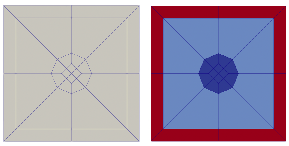
Figure 1: Example RGMB Cartesian pin cell mesh colored by subdomain_id (left) and region_id (right).
Listing 3: Example RGMB Cartesian pin cell.
[Mesh]
  [pin1]
    type = PinMeshGenerator
    reactor_params = rmp
    pin_type = 1
    pitch = 1.42063
    num_sectors = 2
    ring_radii = 0.2
    duct_halfpitch = 0.58
    mesh_intervals = '1 1 1'
    region_ids = '1 2 5'
    quad_center_elements = true
  []
[]
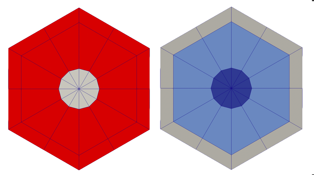
Figure 2: Example RGMB hexagonal pin cell mesh colored by subdomain_id (left) and region_id (right).
Listing 4: Example RGMB hexagonal pin cell.
[Mesh]
  [pin1]
    type = PinMeshGenerator
    reactor_params = rmp
    pin_type = 1
    pitch = 1.42063
    num_sectors = 2
    ring_radii = 0.2
    duct_halfpitch = 0.58
    mesh_intervals = '1 1 1'
    region_ids = '1 2 3'
    quad_center_elements = false
  []
[]
AssemblyMeshGenerator
AssemblyMeshGenerator calls PatternedHexMeshGenerator or PatternedMeshGenerator to generate a Cartesian or hexagonal lattice of pin-like structures. Cartesian and hexagonal examples follow.
RGMB Cartesian Assembly Example
Tips:
Elements belonging to a unique pin cell will be automatically provided a unique
pin_idDucts for Cartesian assemblies are not currently supported
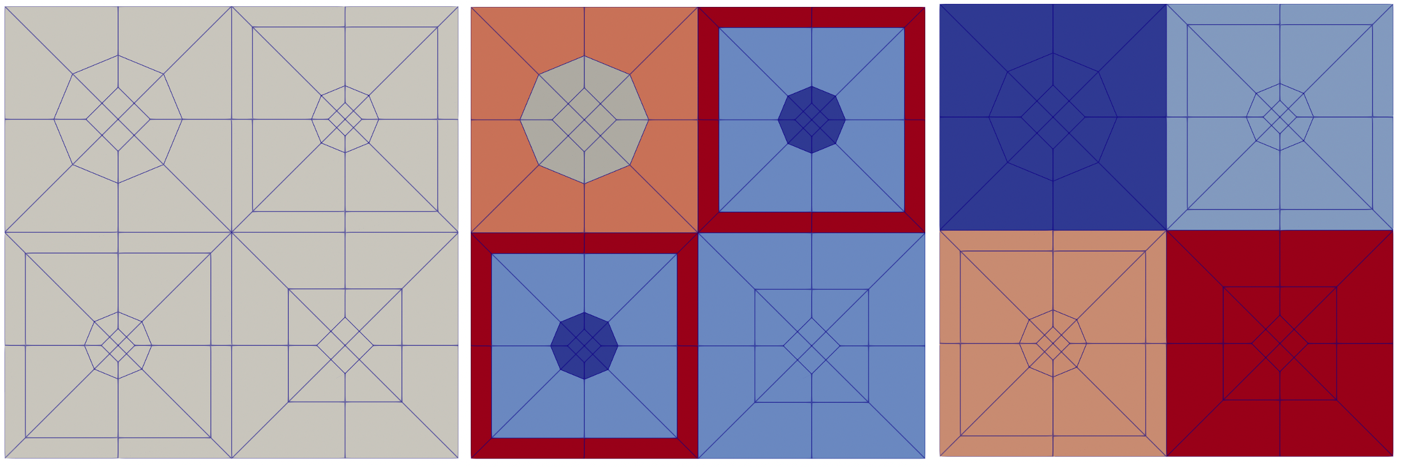
Figure 3: Cartesian assembly colored by subdomain_id (left), region_id (middle), and pin_id (right). Subdomain ids categorize elements as belonging to different subdomains (blocks), region ids categorize elements belonging to different regions (material zones), and pin ids categorize elements belonging to different pin cells.
Listing 5: Example RGMB Cartesian assembly.
[Mesh]
  [assembly1]
    type = AssemblyMeshGenerator
    assembly_type = 2
    inputs = 'pin3 pin1 pin2'
    pattern = '0 1;
               1 2'
  []
[]
RGMB Hexagonal Assembly Example
AssemblyMeshGenerator calls PatternedHexMeshGenerator or PatternedMeshGenerator to generate a Cartesian or hexagonal lattice of pin-like structures.
Tips:
Hexagonal ducts and background coolant region can be added to hexagonal assemblies. The region IDs for the duct and background regions are set by the
duct_region_idsandbackground_region_idparameters.Don't want explicitly defined pins in your assembly? See Reactor Geometry Mesh Builder Example: Homogeneous Sodium-Cooled Fast Reactor Core (ABTR) for how to define homogenized assemblies with AssemblyMeshGenerator.
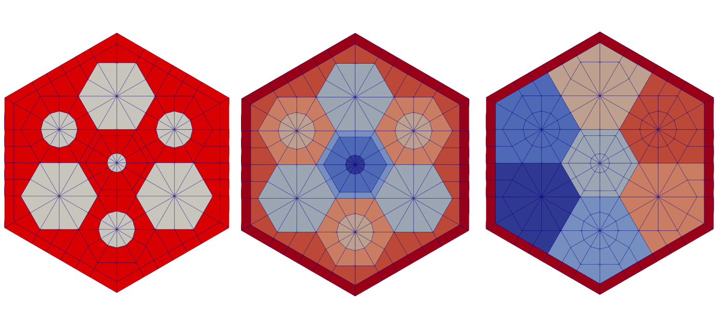
Figure 4: Hexagonal assembly colored by subdomain_id (left), region_id (middle), and pin_id (right). Subdomain ids categorize elements as belonging to different subdomains (blocks), region ids categorize elements belonging to different regions (material zones), and pin ids categorize elements belonging to different pin cells.
Listing 6: Example RGMB hexagonal assembly.
[Mesh]
  [assembly1]
    type = AssemblyMeshGenerator
    assembly_type = 1
    inputs = 'pin1 pin2 pin3'
    pattern = '1 2;
              2 0 1;
               1 2'
    background_intervals = 1
    background_region_id = 7
    duct_intervals = 1
    duct_halfpitch = 2.2
    duct_region_ids = 8
  []
[]
CoreMeshGenerator
CoreMeshGenerator calls PatternedHexMeshGenerator or PatternedMeshGenerator to generate a Cartesian or hexagonal lattice of assembly-like structures.
Defining "dummy_assembly_name" and using it in inputs defines a dummy assembly in the core.
Cartesian Core Example
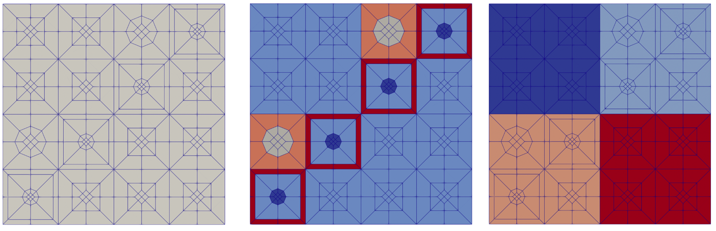
Figure 5: Cartesian core colored by subdomain_id (left), region_id (middle), and assembly_id (right).
Listing 7: Example RGMB Cartesian core.
[Mesh]
  [rgmb_core]
    type = CoreMeshGenerator
    inputs = 'assembly1 assembly2'
    pattern = '1 0;
               0 1'
    extrude = true
  []
[]
Hexagonal Core Example
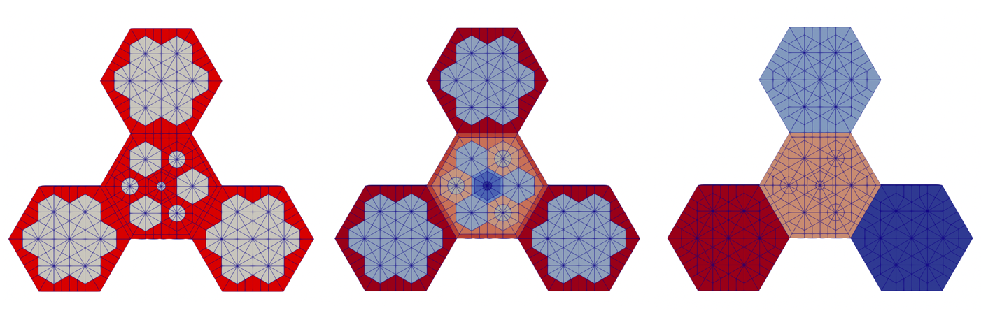
Figure 6: Hexagonal core colored by subdomain_id (left), region_id (middle), and assembly_id (right).
Listing 8: Example RGMB Hexagonal core.
[Mesh]
  [rgmb_core]
    type = CoreMeshGenerator
    inputs = 'assembly1 assembly2 empty'
    dummy_assembly_name = empty
    pattern = '2 1;
              1 0 2;
               2 1'
    extrude = true
  []
[]
CoreMeshGenerator with Peripheral Ring
A core periphery region can be added utilizing either the PeripheralRingMeshGenerator or the PeripheralTriangleMeshGenerator.
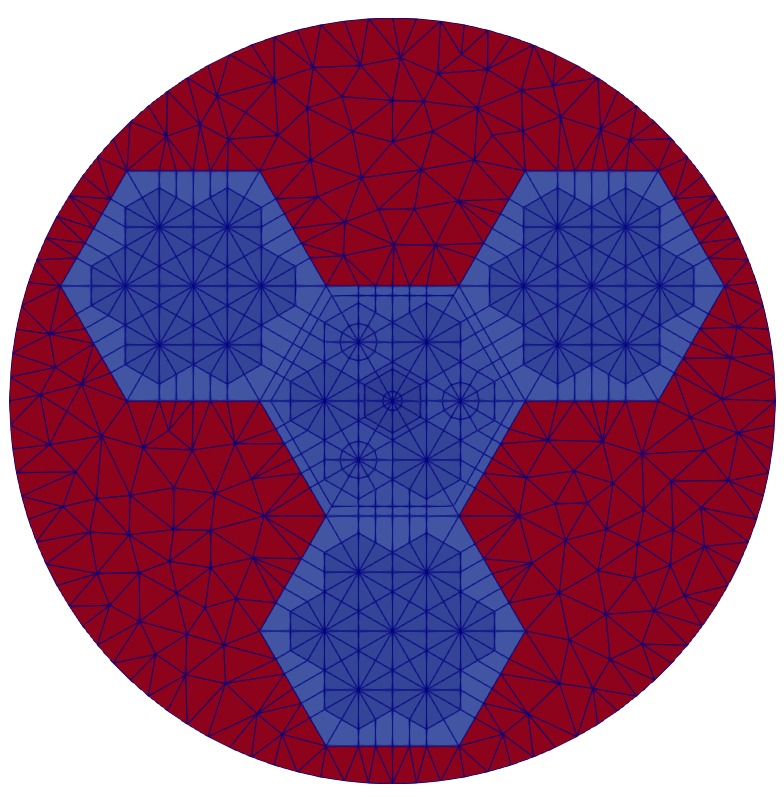
Figure 7: Hexagonal core with core periphery meshed.
Listing 9: Example RGMB Hexagonal core with periphery.
[Mesh]
  [rgmb_core]
    type = CoreMeshGenerator
    inputs = 'assembly1 assembly2 empty'
    dummy_assembly_name = empty
    pattern = '2 1;
              1 0 2;
               2 1'
    extrude = false

    mesh_periphery = true
    periphery_generator = triangle
    periphery_region_id = 100
    outer_circle_radius = 8
    outer_circle_num_segments = 100
    desired_area = 0.5
  []
[]
Default Block and External Boundary Names
An RGMB case can terminate at the pin, assembly, or core "level". Pins and assemblies always have a "type" assigned (a numeric integer specified as "pin_type" for pins and "assembly_type" for assemblies), whereas cores do not. The "level" and "type" are used in the naming schemes for the blocks and outer boundary as follows:
The default block names in the final mesh are
RGMB_(level)(type)andRGMB_(level)(type)_TRI(if triangular elements are present). For example,RGMB_PIN1andRMGB_PIN1_TRI, orRGMB_ASSEMBLY1andRGMB_ASSEMBLY1_TRI, orRGMB_COREandRGMB_CORE_TRI, for workflows ending at the pin, assembly or core level, respectively.The default outer boundary names in the radial dimension are
outer_(level)_(type). For example, for workflows ending at the pin, assembly or core level respectively, the outer boundary names areouter_pin_1,outer_assembly_1andouter_core.If the problem is extruded in the axial dimension, the
topandbottomboundaries also exist.