Step 3: Upper Loop
Complete input file for this step: 03_upper_loop.i
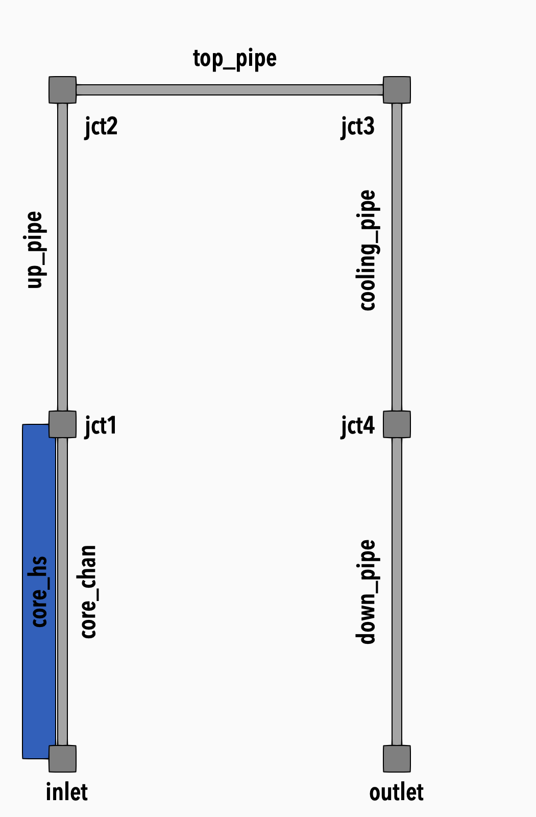
Figure 1: Model diagram
In this step, we will add the flow channels corresponding to the upper part of the loop and the primary side of the heat exchanger. We will explain how to connect flow channels together using junction components and how to specify a convective heat transfer using a specified wall temperature.
Junctions
Junctions are 0-D components that can connect 2 or more flow channels.
In this tutorial we will use so-called volume junctions to connect flow channels to build up the primary loop.
Let's look at an example of a volume junction:
[jct1]
  type = JunctionParallelChannels1Phase
  position = '0 0 1'
  connections = 'core_chan:out up_pipe:in'
  volume = 1e-3
[]
In a volume junction component, users have to specify its location (via the position parameter), its volume via the volume parameter, and list the connected flow channels via the connections parameter.
If the channels are parallel and the cross-sectional area is changing, the type of the junction should be JunctionParallelChannels1Phase.
If the cross-sectional area is the same or the channels are not parallel, the type should be VolumeJunction1Phase.
We also need to specify the initial conditions. Besides the pressure p and temperature T, we need specify velocity initial condition, which has 3 components corresponding to x-, y- and z-dimension.
initial_vel_x = 0
initial_vel_y = 0
initial_vel_z = 0
Since all the junctions will start from the same initial conditions, we can specify those in the [GlobalParams] block, like we did earlier for the flow channels.
Top Part of the Loop
To build the upper part of the loop, we define a global parameter for the pipe diameter.
# pipe parameters
pipe_dia = ${units 10. cm -> m}
This dimension is shared by all the pipes. If we needed to change it later, we can do so just in one place.
The following part of the input file defines all the flow channels and junctions that build up the upper part of the loop
  [jct1]
    type = JunctionParallelChannels1Phase
    position = '0 0 1'
    connections = 'core_chan:out up_pipe:in'
    volume = 1e-3
  []

  [up_pipe]
    type = FlowChannel1Phase
    position = '0 0 1'
    orientation = '0 0 1'
    length = 1
    n_elems = 10
    A = ${fparse pi * pipe_dia * pipe_dia / 4.}
    D_h = ${pipe_dia}
  []

  [jct2]
    type = VolumeJunction1Phase
    position = '0 0 2'
    connections = 'up_pipe:out top_pipe:in'
    volume = 1e-3
  []

  [top_pipe]
    type = FlowChannel1Phase
    position = '0 0 2'
    orientation = '1 0 0'
    length = 1
    n_elems = 10
    A = ${fparse pi * pipe_dia * pipe_dia / 4.}
    D_h = ${pipe_dia}
  []

  [jct3]
    type = VolumeJunction1Phase
    position = '1 0 2'
    connections = 'top_pipe:out cooling_pipe:in'
    volume = 1e-3
  []

  [cooling_pipe]
    type = FlowChannel1Phase
    position = '1 0 2'
    orientation = '0 0 -1'
    length = 1
    n_elems = 10
    A = ${fparse pi * pipe_dia * pipe_dia / 4.}
    D_h = ${pipe_dia}
  []

  [cold_wall]
    type = HeatTransferFromSpecifiedTemperature1Phase
    flow_channel = cooling_pipe
    T_wall = 300
    Hw = 0.97
  []
In the heat exchanger section, we only build the primary side and connect it to HeatTransferFromSpecifiedTemperature1Phase. This component requires the T_wall parameter – wall temperature and Hw convective wall heat transfer coefficient (this is a requirement of Closures1PhaseSimple). Using a simplified secondary side is a good first step when building a heat exchanger model.
Postprocessors
The postprocessor system comes from the MOOSE framework. Postprocessors are single Real values computed at different locations like blocks, sides, etc., or at different mesh entities like nodes or elements. There can also be postprocessors that are not associated with any mesh entities (like a postprocessor to output time step size, etc.).
In our model, we will add the two following postprocessors:
core_T_outfor monitoring core outlet temperature[core_T_out] type = SideAverageValue boundary = core_chan:out variable = T []hx_pri_T_outfor monitoring heat exchanger outlet temperature[hx_pri_T_out] type = SideAverageValue boundary = cooling_pipe:out variable = T []
Both postprocessors are of SideAverageValue type which means they are computed on a side. The side is specified via the boundary parameter and both postprocessors operate on the temperature variable T.
Notes
THM also provides components like pumps and valves, which behave like junctions. However, they may have some limitations on the number of connected channels. For example, a pump component might have only a single inlet and a single outlet.
The single-phase flow model does not support mixing of fluids. This means you cannot bring 2 different fluids into a junction and have their mixture produced at the junction outlet. The code will detect this problem and report an error, if you do so.