Heat Conduction System Design Description
This template follows INL template TEM-140, "IT System Design Description."
This document serves as an addendum to Framework System Design Description and captures information for Software Design Description (SDD) specific to the Heat Conduction application.
Introduction
Frameworks are a software development construct aiming to simplify the creation of specific classes of applications through abstraction of low-level details. The main object of creating a framework is to provide an interface to application developers that saves time and provides advanced capabilities not attainable otherwise. The MOOSE, mission is just that: provide a framework for engineers and scientists to build state-of-the-art, computationally scalable finite element based simulation tools.
MOOSE was conceived with one major objective: to be as easy and straightforward to use by scientists and engineers as possible. MOOSE is meant to be approachable by non-computational scientists who have systems of PDEs they need to solve. Every single aspect of MOOSE was driven by this singular principle from the build system to the API to the software development cycle. At every turn, decisions were made to enable this class of users to be successful with the framework. The pursuit of this goal has led to many of the unique features of MOOSE:
A streamlined build system
An API aimed at extensible
Straightforward APIs providing sensible default information
Integrated, automatic, and rigorous testing
Rapid, continuous integration development cycle
Codified, rigorous path for contributing
Applications are modular and composable
Each of these characteristics is meant to build trust in the framework by those attempting to use it. For instance, the build system is the first thing potential framework users come into contact with when they download a new software framework. Onerous dependency issues, complicated, hard to follow instructions or build failure can all result in a user passing on the platform. Ultimately, the decision to utilize a framework comes down to whether or not you trust the code in the framework and those developing it to be able to support your desired use-case. No matter the technical capabilities of a framework, without trust users will look elsewhere. This is especially true of those not trained in software development or computational science.
Developing trust in a framework goes beyond utilizing "best practices" for the code developed, it is equally important that the framework itself is built upon tools that are trusted. For this reason, MOOSE relies on a well-established code base of libMesh and PETSc. The libMesh library provides foundational capability for the finite element method and provides interfaces to leading-edge numerical solution packages such as PETSc.
With these principles in mind, an open source, massively parallel, finite element, multiphysics framework has been conceived. MOOSE is an on-going project started in 2008 aimed toward a common platform for creation of new multiphysics tools. This document provides design details pertinent to application developers as well as framework developers.
Use Cases
The MOOSE Framework is targeted at two main groups of actors: Developers and Users. Developers are the main use case. These are typically students and professionals trained in science and engineering fields with some level of experience with coding but typically very little formal software development training. The other user group is Users. Those who intend to use an application built upon the framework without writing any computer code themselves. Instead they may modify or create input files for driving a simulation, run the application, and analyze the results. All interactions through MOOSE are primarily through the command-line interface and through a customizable block-based input file.
System Purpose
The Software Design Description provided here is description of each object in the system. The pluggable architecture of the framework makes MOOSE and MOOSE-based applications straightforward to develop as each piece of end-user (developer) code that goes into the system follows a well-defined interface for the underlying systems that those object plug into. These descriptions are provided through developer-supplied "markdown" files that are required for all new objects that are developed as part of the framework, modules and derivative applications. More information about the design documentation can be found in Documenting MOOSE.
System Scope
The purpose of this software is to provide several libraries that can be used to build an application based upon the framework. Additionally, several utilities are provided for assisting developers and users in end-to-end FEM analysis. A brief overview of the major components are listed here:
| Component | Description |
|---|---|
| framework library | The base system from which all MOOSE-based applications are created |
| module libraries | Optional "physics" libraries that may be used in an application to provide capability |
| build system | The system responsible for creating applications for a series of libraries and applications |
| test harness | The extendable testing system for finding, scheduling, running, and reporting regression tests |
| "peacock" | The GUI for building input files, executing applications, and displaying results |
| MooseDocs | The extendable markdown system for MOOSE providing common documentation and requirements enforcement |
| "stork" | The script and templates for generating a new MOOSE-based application ready for building and testing |
| examples | A set of complete applications demonstrating the use of MOOSE's pluggable systems |
| tutorials | Step by step guides to building up an application using MOOSE's pluggable systems |
| unit | An application for unit testing individual classes or methods of C++ code |
Dependencies and Limitations
The MOOSE platform has several dependencies on other software packages and has scope that is constantly evolving based upon funding, resources, priorities, and lab direction. However, the software is open-source and many features and even bugs can be offloaded to developers with appropriate levels of knowledge and direction from the main design team. The primary list of software dependencies is listed below. This list is not meant to be exhaustive. Individual operating systems may require specific packages to be installed prior to using MOOSE, which can be found on the Install MOOSE pages.
| Software Dependency | Description |
|---|---|
| libMesh | Finite Element Library and I/O routines |
| PETSc | Solver Package |
| hypre | Multigrid Preconditioner |
| MPI | A distributed parallel processing library (MPICH) |
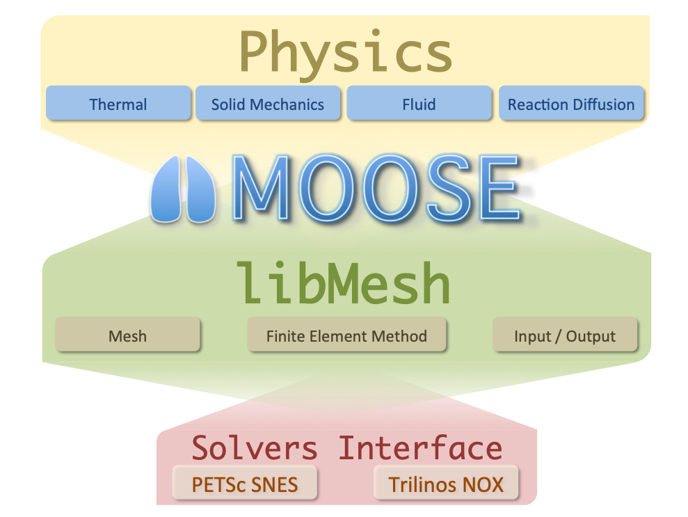
Figure 1: A diagram of the MOOSE code platform.
References
Definitions and Acronyms
This section defines, or provides the definition of, all terms and acronyms required to properly understand this specification.
Definitions
- Pull (Merge) Request: A proposed change to the software (e.g. usually a code change, but may also include documentation, requirements, design, and/or testing). - Baseline: A specification or product (e.g., project plan, maintenance and operations (M&O) plan, requirements, or design) that has been formally reviewed and agreed upon, that thereafter serves as the basis for use and further development, and that can be changed only by using an approved change control process (NQA-1, 2009). - Validation: Confirmation, through the provision of objective evidence (e.g., acceptance test), that the requirements for a specific intended use or application have been fulfilled (24765:2010(E), 2010). - Verification: (1) The process of: evaluating a system or component to determine whether the products of a given development phase satisfy the conditions imposed at the start of that phase. (2) Formal proof of program correctness (e.g., requirements, design, implementation reviews, system tests) (24765:2010(E), 2010).
Acronyms
| Acronym | Description |
|---|---|
| API | Application Programming Interface |
| DOE-NE | Department of Energy, Nuclear Energy |
| FE | finite element |
| FEM | Finite Element Method |
| GUI | graphical user interface |
| HIT | Hierarchical Input Text |
| HPC | High Performance Computing |
| I/O | Input/Output |
| INL | Idaho National Laboratory |
| MOOSE | Multiphysics Object Oriented Simulation Environment |
| MPI | Message Passing Interface |
| PDEs | partial differential equations |
| SDD | Software Design Description |
Design Stakeholders and Concerns
Design Stakeholders
Stakeholders for MOOSE include several of the funding sources including DOE-NE and the INL. However, Since MOOSE is an open-source project, several universities, companies, and foreign governments have an interest in the development and maintenance of the MOOSE project.
Stakeholder Design Concerns
Concerns from many of the stakeholders are similar. These concerns include correctness, stability, and performance. The mitigation plan for each of these can be addressed. For correctness, MOOSE development requires either regression or unit testing for all new code added to the repository. The project contains several comparisons against analytical solutions where possible and also other verification methods such as MMS. For stability, MOOSE maintains multiple branches to incorporate several layers of testing both internally and for dependent applications. Finally, performance tests are also performed as part of the the normal testing suite to monitor code change impacts to performance.
System Design
The MOOSE framework itself is composed of a wide range of pluggable systems. Each system is generally composed of a single or small set of C++ objects intended to be specialized by a Developer to solve a specific problem. To accomplish this design goal, MOOSE uses several modern object-oriented design patterns. The primary overarching pattern is the "Factory Pattern". Users needing to extend MOOSE may inherit from one of MOOSE's systems to providing an implementation meeting his or her needs. The design of each of these systems is documented on the mooseframework.org wiki in the Tutorial section. Additionally, up-to-date documentation extracted from the source is maintained on the the mooseframework.org documentation site after every successful merge to MOOSE's stable branch. After these objects are created, the can be registered with the framework and used immediately in a MOOSE input file.
System Structure
The MOOSE framework architecture consists of a core and several pluggable systems. The core of MOOSE consists of a number of key objects responsible for setting up and managing the user-defined objects of a finite element simulation. This core set of objects has limited extendability and exist for every simulation configuration that the framework is capable of running.
Adaptivity
Adaptivity/Indicators
Adaptivity/Markers
AuxKernels
AuxKernels/MatVecRealGradAuxKernel
AuxKernels/MaterialVectorAuxKernel
AuxKernels/MaterialVectorGradAuxKernel
AuxScalarKernels
AuxVariables
AuxVariables/MultiAuxVariables
BCs
BCs/CavityPressure
BCs/CoupledPressure
BCs/InclinedNoDisplacementBC
BCs/Periodic
BCs/Pressure
Bounds
Closures
Components
Constraints
Contact
ControlLogic
Controls
CoupledHeatTransfers
Covariance
DGKernels
Dampers
Debug
Debug/MaterialDerivativeTest
DeprecatedBlock
DiracKernels
Distributions
DomainIntegral
Executioner
Executioner/Adaptivity
Executioner/Predictor
Executioner/Quadrature
Executioner/TimeIntegrator
Executioner/TimeStepper
Executors
FVBCs
FVInterfaceKernels
FVKernels
FluidPropertiesInterrogator
Functions
GeochemicalModelInterrogator
GlobalParams
GrayDiffuseRadiation
HeatStructureMaterials
ICs
ICs/PolycrystalICs
ICs/PolycrystalICs/BicrystalBoundingBoxIC
ICs/PolycrystalICs/BicrystalCircleGrainIC
ICs/PolycrystalICs/PolycrystalColoringIC
ICs/PolycrystalICs/PolycrystalRandomIC
ICs/PolycrystalICs/PolycrystalVoronoiVoidIC
ICs/PolycrystalICs/Tricrystal2CircleGrainsIC
InterfaceKernels
Kernels
Kernels/CHPFCRFFSplitKernel
Kernels/DynamicTensorMechanics
Kernels/HHPFCRFFSplitKernel
Kernels/PFCRFFKernel
Kernels/PolycrystalElasticDrivingForce
Kernels/PolycrystalKernel
Kernels/PolycrystalStoredEnergy
Kernels/PoroMechanics
Kernels/RigidBodyMultiKernel
Kernels/TensorMechanics
Materials
Mesh
Mesh/Partitioner
Modules
Modules/CompressibleNavierStokes
Modules/FluidProperties
Modules/HeatConduction
Modules/HeatConduction/ThermalContact
Modules/HeatConduction/ThermalContact/BC
Modules/IncompressibleNavierStokes
Modules/NavierStokesFV
Modules/Peridynamics
Modules/Peridynamics/Mechanics
Modules/Peridynamics/Mechanics/GeneralizedPlaneStrain
Modules/Peridynamics/Mechanics/Master
Modules/PhaseField
Modules/PhaseField/Conserved
Modules/PhaseField/DisplacementGradients
Modules/PhaseField/EulerAngles2RGB
Modules/PhaseField/GrainGrowth
Modules/PhaseField/GrandPotential
Modules/PhaseField/Nonconserved
Modules/PorousFlow
Modules/PorousFlow/BCs
Modules/TensorMechanics
Modules/TensorMechanics/CohesiveZoneMaster
Modules/TensorMechanics/DynamicMaster
Modules/TensorMechanics/GeneralizedPlaneStrain
Modules/TensorMechanics/GlobalStrain
Modules/TensorMechanics/LineElementMaster
Modules/TensorMechanics/Master
Modules/TensorMechanics/MaterialVectorBodyForce
MortarGapHeatTransfer
MultiApps
NodalKernels
NodalNormals
Outputs
PorousFlowBasicTHM
PorousFlowFullySaturated
PorousFlowUnsaturated
Postprocessors
Preconditioning
Problem
RayBCs
RayKernels
ReactionNetwork
ReactionNetwork/AqueousEquilibriumReactions
ReactionNetwork/SolidKineticReactions
Reporters
Samplers
ScalarKernels
SpatialReactionSolver
StochasticTools
Surrogates
ThermalContact
TimeDependentReactionSolver
TimeIndependentReactionSolver
Trainers
Transfers
UserObjects
Variables
Variables/CHPFCRFFSplitVariables
Variables/HHPFCRFFSplitVariables
Variables/PFCRFFVariables
Variables/PolycrystalVariables
VectorPostprocessors
XFEM
The MooseApp is the top-level object used to hold all of the other objects in a simulation. In a normal simulation a single MooseApp object is created and "run()". This object uses it's Factory objects to build user defined objects which are stored in a series of Warehouse objects and executed. The Finite Element data is stored in the Systems and Assembly object while the domain information (the Mesh) is stored in the Mesh object. A series of threaded loops are used to run parallel calculations on the objects created and stored within the warehouses.
MOOSE's pluggable systems are documented on the mooseframework.org wiki. Each of these systems has set of defined polymorphic interfaces and are designed to accomplish a specific task within the simulation. The design of these systems is fluid and is managed through agile methods and ticket request system on the Github.org website.
Data Design and Control
At a high level, the system is designed to process HIT input files to construct several objects that will constitute an FE simulation. Some of the objects in the simulation may in turn load other file-based resources to complete the simulation. Examples include meshes or data files. The system will then assemble systems of equations and solve them using the libraries of the Code Platform. The system can then output the solution in one or more supported output formats commonly used for visualization.
Human-Machine Interface Design
MOOSE is a command-line driven program. All interaction with MOOSE and MOOSE-based codes is ultimately done through the command line. This is typical for HPC applications that use the MPI interface for running on super computing clusters. Optional GUIs may be used to assist in creating input files and launching executables on the command line.
System Design Interface
All external system interaction is performed either through file I/O or through local API calls. Neither the framework, nor the modules are designed to interact with any external system directly through remote procedure calls. Any code to code coupling performed using the framework are done directly through API calls either in a static binary or after loading shared libraries.
Security Structure
The framework does not require any elevated privileges to operate and does not run any stateful services, daemons or other network programs. Distributed runs rely on the MPI library.
Requirements Cross-Reference
- heat_conduction: HeatConductionTimeDerivative
- 5.1.1The system shall compute the transient heat conduction solution for the NAFEMS T3 benchmark problem using a coarse mesh and
- HEX8 elements
- HEX20 elements
- HEX27 elements
- EDGE2 elements
- EDGE3 elements
- QUAD4 elements
- QUAD8 elements
- QUAD9 elements
Specification(s): coarse_mesh/hex8, coarse_mesh/hex20, coarse_mesh/hex27, coarse_mesh/edge2, coarse_mesh/edge3, coarse_mesh/quad4, coarse_mesh/quad8, coarse_mesh/quad9
Design: HeatConductionTimeDerivative
Issue(s): #14838
Collection(s): FUNCTIONAL
Type(s): CSVDiff
- 5.1.2The system shall compute the transient heat conduction solution for the NAFEMS T3 benchmark problem using a fine mesh and
- HEX8 mesh
- HEX20 mesh
- HEX27 mesh
- EDGE2 mesh
- EDGE3 mesh
- QUAD4 mesh
- QUAD8 mesh
- QUAD9 mesh
Specification(s): fine_mesh/hex8, fine_mesh/hex20, fine_mesh/hex27, fine_mesh/edge2, fine_mesh/edge3, fine_mesh/quad4, fine_mesh/quad8, fine_mesh/quad9
Design: HeatConductionTimeDerivative
Issue(s): #14838
Collection(s): FUNCTIONAL
Type(s): CSVDiff
- heat_conduction: ADConvectiveHeatFluxBC
- 5.2.1The system shall provide a convective flux boundary condition which uses material properties as heat transfer coefficients and far-field temperature values using AD
- and match hand calculations for flux through a boundary.
- and approach a constant far-field temperature value over time as heat flux decreases.
- and couple a temperature dependent far-field temperature and heat transfer coefficient.
Specification(s): g/flux, g/equilibrium, g/coupled
Design: ADConvectiveHeatFluxBC
Issue(s): #11631
Collection(s): FUNCTIONAL
Type(s): CSVDiff
- heat_conduction: ADHeatConduction
- 5.3.1AD heat conduction and the Jacobian shall be beautiful
Specification(s): jacobian_test
Design: ADHeatConduction
Collection(s): FUNCTIONAL
Type(s): PetscJacobianTester
- heat_conduction: HeatConduction
- 5.4.1The MOOSE solutions shall converge to the analytic solutions with an expected order of accuracy (two for linear, three for quadratic) where a standard set of heat conduction problems is used for code verification.
Specification(s): spatial_csv
Design: HeatConduction
Issue(s): #15301
Collection(s): FUNCTIONAL
Type(s): CSVDiff
- 5.19.1The system shall compute a tri-linear temperature field
Specification(s): test
Design: HeatConduction
Issue(s): #6750
Collection(s): FUNCTIONAL
Type(s): Exodiff
- 5.19.2The system shall compute a bi-linear temperature field for an axisymmetric problem with quad8 elements
Specification(s): test_rz_quad8
Design: HeatConduction
Issue(s): #6750
Collection(s): FUNCTIONAL
Type(s): Exodiff
- 5.19.3The system shall compute a bi-linear temperature field for an axisymmetric problem
Specification(s): test_rz
Design: HeatConduction
Issue(s): #6750
Collection(s): FUNCTIONAL
Type(s): Exodiff
- 5.19.4The system shall compute a tri-linear temperature field with hex20 elements
Specification(s): test_hex20
Design: HeatConduction
Issue(s): #6750
Collection(s): FUNCTIONAL
Type(s): Exodiff
- 5.19.5The system shall compute a tri-linear temperature field with hex20 elements using an anisotropic thermal conductivity model with isotropic thermal conductivities supplied
Specification(s): test_hex20_aniso
Design: HeatConduction
Issue(s): #6750
Collection(s): FUNCTIONAL
Type(s): Exodiff
- 5.36.1Heat conduction shall match the answer from an analytical solution in 1D
Specification(s): 1D_transient
Design: HeatConduction
Issue(s): #5975
Collection(s): FUNCTIONAL
Type(s): Exodiff
- 5.36.2Heat conduction from an AD kernel shall get the same answer as a traditional kernel in 1D
Specification(s): ad_1D_transient
Design: HeatConduction
Collection(s): FUNCTIONAL
Type(s): Exodiff
- 5.36.3AD heat conduction and the Jacobian shall be beautiful in 1D
Specification(s): ad_1D_transient_jacobian
Design: HeatConduction
Collection(s): FUNCTIONAL
Type(s): PetscJacobianTester
- 5.36.4Heat conduction shall match the answer from an analytical solution in 2D
Specification(s): 2D_steady_state
Design: HeatConduction
Issue(s): #8194
Collection(s): FUNCTIONAL
Type(s): Exodiff
- 5.36.5Heat conduction from an AD kernel shall get the same answer as a traditional kernel in 2D
Specification(s): ad_2D_steady_state
Design: HeatConduction
Collection(s): FUNCTIONAL
Type(s): Exodiff
- 5.36.6AD heat conduction and the Jacobian shall be beautiful in 2D
Specification(s): ad_2D_steady_state_jacobian
Design: HeatConduction
Collection(s): FUNCTIONAL
Type(s): PetscJacobianTester
- heat_conduction: ConjugateHeatTransfer
- 5.5.1The system shall correctly model convection heat transfer across internal sidesets aka conjugate heat transfer.
Specification(s): convection
Design: ConjugateHeatTransfer
Issue(s): #15114
Collection(s): FUNCTIONAL
Type(s): Exodiff
- heat_conduction: ConvectiveFluxFunction
- 5.6.1The system shall allow prescribing a convective flux boundary condition using a constant heat transfer coefficient.
Specification(s): constant
Design: ConvectiveFluxFunction
Issue(s): #14418
Collection(s): FUNCTIONAL
Type(s): CSVDiff
- 5.6.2The system shall allow prescribing a convective flux boundary condition using a heat transfer coefficient that is a function of position and time.
Specification(s): time_dependent
Design: ConvectiveFluxFunction
Issue(s): #14418
Collection(s): FUNCTIONAL
Type(s): CSVDiff
- 5.6.3The system shall allow prescribing a convective flux boundary condition using a heat transfer coefficient that is a function of temperature.
Specification(s): temperature_dependent
Design: ConvectiveFluxFunction
Issue(s): #14418
Collection(s): FUNCTIONAL
Type(s): CSVDiff
- heat_conduction: ConvectiveHeatFluxBC
- 5.7.1The system shall provide a convective flux boundary condition which uses material properties as heat transfer coefficients and far-field temperature values
- and match hand calculations for flux through a boundary.
- and approach a constant far-field temperature value over time as heat flux decreases.
- and couple a temperature dependent far-field temperature and heat transfer coefficient.
Specification(s): g/flux, g/equilibrium, g/coupled
Design: ConvectiveHeatFluxBC
Issue(s): #11631
Collection(s): FUNCTIONAL
Type(s): CSVDiff
- heat_conduction: FunctionPathEllipsoidHeatSource
- 5.8.1The system shall produce a moving heat source where its path is function dependent
Specification(s): test
Design: FunctionPathEllipsoidHeatSource
Issue(s): #15795
Collection(s): FUNCTIONAL
Type(s): CSVDiff
- heat_conduction: FVInfiniteCylinderRadiativeBC
- 5.9.1The system shall be able to solve a heat conduction problem with boundary conditions representing radiation to an infinite cylinder.
Specification(s): infinite_cylinder_radiation
Design: FVInfiniteCylinderRadiativeBC
Issue(s): #18626
Collection(s): FUNCTIONAL
Type(s): Exodiff
- heat_conduction: FVThermalResistanceBC
- 5.9.2The system shall be able to solve a heat conduction problem with diffusion/conduction/radiation combined thermal resistance boundary conditions
- using regular material properties.
- using regular material properties in RZ geometry.
- using functor material properties.
- using functor material properties in RZ geometry.
Specification(s): thermal_resistance/matprop, thermal_resistance/matprop_rz, thermal_resistance/functor_matprop, thermal_resistance/functor_matprop_rz
Design: FVThermalResistanceBC
Issue(s): #18626
Collection(s): FUNCTIONAL
Type(s): Exodiff
- heat_conduction: GapHeatTransfer
- 5.10.1Energy balance must be fulfilled for the heat transfer of concentric spheres involving radiation, when the gap distance is not negligible with respect to the body main dimensions.
Specification(s): large_gap_heat_transfer_test_sphere
Design: GapHeatTransfer
Issue(s): #18585
Collection(s): FUNCTIONAL
Type(s): CSVDiff
- 5.10.2Energy balance must be fulfilled for the heat transfer of concentric cylinders involving radiation in two-dimensions, when the gap distance is not negligible with respect to the body main dimensions.
Specification(s): large_gap_heat_transfer_test_rz_cylinder
Design: GapHeatTransfer
Issue(s): #18585
Collection(s): FUNCTIONAL
Type(s): CSVDiff
- 5.10.3Energy balance must be fulfilled for the heat transfer of concentric cylinders involving radiation in two-dimensions with axisymmetry, when the gap distance is not negligible with respect to the body main dimensions.
Specification(s): large_gap_heat_transfer_test_cylinder
Design: GapHeatTransfer
Issue(s): #18585
Collection(s): FUNCTIONAL
Type(s): CSVDiff
- 5.11.1Thermal contact shall solve plate heat transfer for a constant conductivity gap in 3D
Specification(s): 3D
Design: GapHeatTransfer
Issue(s): #1609
Collection(s): FUNCTIONAL
Type(s): Exodiff
- 5.11.2Thermal contact shall solve plate heat transfer for a constant conductivity gap in 3D using the Modules/HeatConduction/Thermal contact syntax
Specification(s): syntax
Design: GapHeatTransfer
Issue(s): #1609
Collection(s): FUNCTIONAL
Type(s): Exodiff
- 5.11.3Thermal contact shall solve plate heat transfer for a constant conductivity gap in 3D at each iteration
Specification(s): 3D_Iters
Design: GapHeatTransfer
Issue(s): #1609
Collection(s): FUNCTIONAL
Type(s): Exodiff
- 5.11.4Thermal contact shall solve cylindrical and plate heat transfer for a constant conductivity gap in 2D axisymmetric coordinates
Specification(s): RZ
Design: GapHeatTransfer
Issue(s): #5104
Collection(s): FUNCTIONAL
Type(s): Exodiff
- 5.11.5Thermal contact shall solve cylindrical heat transfer for a constant conductivity gap in 2D axisymmetric coordinates where the axial axis is along the x-direction
Specification(s): ZR
Design: GapHeatTransfer
Issue(s): #12071
Collection(s): FUNCTIONAL
Type(s): Exodiff
- 5.11.6Thermal contact shall solve spherical heat transfer for a constant conductivity gap in 1D spherically symmetric coordinates
Specification(s): RSpherical
Design: GapHeatTransfer
Collection(s): FUNCTIONAL
Type(s): Exodiff
- 5.11.7Thermal contact shall solve cylindrical heat transfer for a constant conductivity gap in 3D
Specification(s): cyl3D
Design: GapHeatTransfer
Issue(s): #6161
Collection(s): FUNCTIONAL
Type(s): Exodiff
- 5.11.8Thermal contact shall solve cylindrical heat transfer for a constant conductivity gap in the x-y plane
Specification(s): cyl2D
Design: GapHeatTransfer
Issue(s): #6161
Collection(s): FUNCTIONAL
Type(s): Exodiff
- 5.11.9Thermal contact shall solve spherical heat transfer for a constant conductivity gap in 3D
Specification(s): sphere3D
Design: GapHeatTransfer
Issue(s): #6161
Collection(s): FUNCTIONAL
Type(s): Exodiff
- 5.11.10Thermal contact shall solve spherical heat transfer for a constant conductivity gap in 2D axisymmetric coordinates
Specification(s): sphere2DRZ
Design: GapHeatTransfer
Issue(s): #6161
Collection(s): FUNCTIONAL
Type(s): Exodiff
- 5.11.11Thermal contact shall solve cylindrical heat transfer for a constant conductivity gap in the x-z plane
Specification(s): cyl2D_xz
Design: GapHeatTransfer
Issue(s): #11913
Collection(s): FUNCTIONAL
Type(s): Exodiff
- 5.11.12Thermal contact shall solve cylindrical heat transfer for a constant conductivity gap in the y-z plane
Specification(s): cyl2D_yz
Design: GapHeatTransfer
Issue(s): #11913
Collection(s): FUNCTIONAL
Type(s): Exodiff
- 5.11.13Thermal contact shall solve plate heat transfer for a constant conductivity gap in the x-y plane
Specification(s): planar_xy
Design: GapHeatTransfer
Issue(s): #11913
Collection(s): FUNCTIONAL
Type(s): Exodiff
- 5.11.14Thermal contact shall solve plate heat transfer for a constant conductivity gap in the x-z plane
Specification(s): planar_xz
Design: GapHeatTransfer
Issue(s): #11913
Collection(s): FUNCTIONAL
Type(s): Exodiff
- 5.11.15Thermal contact shall solve plate heat transfer for a constant conductivity gap in the y-z plane
Specification(s): planar_yz
Design: GapHeatTransfer
Issue(s): #11913
Collection(s): FUNCTIONAL
Type(s): Exodiff
- 5.14.1The system shall be able to compute heat flux across a gap using the ThermalContact methods
Specification(s): test
Design: GapHeatTransfer
Issue(s): #1609
Collection(s): FUNCTIONAL
Type(s): Exodiff
- 5.17.18Optionally a constant attenuation shall be applied to compute the gap conductance below a gap length threshold.
Specification(s): min_gap_order_zero
Design: GapConductanceGapHeatTransfer
Issue(s): #13221
Collection(s): FUNCTIONAL
Type(s): CSVDiff
- 5.17.19Optionally a linear Taylor expansion of the inverse gap length shall be applied as the attenuation to compute the gap conductance below a gap length threshold.
Specification(s): min_gap_order_one
Design: GapConductanceGapHeatTransfer
Issue(s): #13221
Collection(s): FUNCTIONAL
Type(s): CSVDiff
- 5.23.1The ThermalContact system shall enforce heat transfer across a meshed gap in a 2D plane geometry.
Specification(s): test
Design: ThermalContact SystemGapHeatTransfer
Issue(s): #716
Collection(s): FUNCTIONAL
Type(s): Exodiff
- 5.23.4The ThermalContact system shall enforce heat transfer across a meshed circular annulus in a 2D plane geometry.
Specification(s): annulus
Design: ThermalContact SystemGapHeatTransfer
Issue(s): #716
Collection(s): FUNCTIONAL
Type(s): Exodiff
- heat_conduction: Constraints System
- 5.12.1We shall be able to produce the expected result for a gap conductance test case using the mortar method.
Specification(s): test
Design: Constraints SystemModular Gap Conductance Constraint
Collection(s): FUNCTIONAL
Type(s): Exodiff
- 5.12.2We shall be able to produce the expected result for a gap conductance test case using the mortar method using the modular gap flux system.
Specification(s): modular
Design: Constraints SystemModular Gap Conductance Constraint
Collection(s): FUNCTIONAL
Type(s): Exodiff
- 5.12.3We shall be able to produce the expected result for a combined gap conductance and radiative heat transfer test case using the mortar method using the modular gap flux system
Specification(s): modular_multiple
Design: Constraints SystemModular Gap Conductance Constraint
Collection(s): FUNCTIONAL
Type(s): Exodiff
- 5.12.4We shall be able to run the mortar method on a displaced mesh, supplying the displacements with constant** auxiliary variables
Specification(s): displaced
Design: Constraints SystemModular Gap Conductance Constraint
Collection(s): FUNCTIONAL
Type(s): Exodiff
- 5.12.5We shall be able to produce the expected result for a gap conductance test case using the mortar method using the modular gap flux system with a displaced mesh.
Specification(s): modular_displaced
Design: Constraints SystemModular Gap Conductance Constraint
Collection(s): FUNCTIONAL
Type(s): Exodiff
- 5.12.6The system shall accurately calculate axisymmetric coordinates on mortar finite element segments
Specification(s): displaced_rz
Design: Constraints SystemModular Gap Conductance Constraint
Collection(s): FUNCTIONAL
Type(s): Exodiff
- 5.12.7We shall be able to generate node-to-segment numerical results for radiation through plates and use it as a reference for mortar-based constraints.
Specification(s): bc_gap_heat_transfer_displaced_radiation
Design: Constraints SystemModular Gap Conductance Constraint
Collection(s): FUNCTIONAL
Type(s): CSVDiff
- 5.12.8We shall be able to generate mortar numerical results for radiation through plates that are close to those generated by the node-to-segment formulation.
Specification(s): modular_gap_heat_transfer_mortar_displaced_radiation
Design: Constraints SystemModular Gap Conductance Constraint
Collection(s): FUNCTIONAL
Type(s): CSVDiff
- 5.12.9We shall be able to generate node-to-segment numerical results for conduction through plates and use it as a reference for mortar-based constraints.
Specification(s): bc_gap_heat_transfer_displaced_conduction
Design: Constraints SystemModular Gap Conductance Constraint
Collection(s): FUNCTIONAL
Type(s): CSVDiff
- 5.12.10We shall be able to generate mortar numerical results for conduction through plates that are close to those generated by the node-to-segment formulation.
Specification(s): modular_gap_heat_transfer_mortar_displaced_conduction
Design: Constraints SystemModular Gap Conductance Constraint
Collection(s): FUNCTIONAL
Type(s): CSVDiff
- 5.12.11We shall be able to generate node-to-segment numerical results for conduction and radiation through cylinders and use it as a reference for mortar-based constraints.
Specification(s): large_gap_heat_transfer_test_cylinder
Design: Constraints SystemModular Gap Conductance Constraint
Collection(s): FUNCTIONAL
Type(s): CSVDiff
- 5.12.12We shall be able to generate mortar numerical results for conduction and radiationthrough cylinders that are close to those generated by the node-to-segment formulation.
Specification(s): large_gap_heat_transfer_test_cylinder_mortar
Design: Constraints SystemModular Gap Conductance Constraint
Collection(s): FUNCTIONAL
Type(s): CSVDiff
- 5.12.13We shall be able to generate node-to-segment numerical results for conduction and radiation through cylinders with axisymmetry and use it as a reference for mortar-based constraints.
Specification(s): large_gap_heat_transfer_test_rz_cylinder
Design: Constraints SystemModular Gap Conductance Constraint
Collection(s): FUNCTIONAL
Type(s): CSVDiff
- 5.12.14We shall be able to generate mortar numerical results for conduction and radiationthrough cylinders with axisymmetry that are close to those generated by the node-to-segment formulation.
Specification(s): large_gap_heat_transfer_test_rz_cylinder_mortar
Design: Constraints SystemModular Gap Conductance Constraint
Collection(s): FUNCTIONAL
Type(s): CSVDiff
- 5.12.15We shall be able to generate node-to-segment numerical results for conduction and radiation through concentric spheres with axisymmetry and use it as a reference for mortar-based constraints.
Specification(s): large_gap_heat_transfer_test_sphere
Design: Constraints SystemModular Gap Conductance Constraint
Collection(s): FUNCTIONAL
Type(s): CSVDiff
- 5.12.16We shall be able to generate mortar numerical results for conduction and radiation through concentric spheres with axisymmetry that are close to those generated by the node-to-segment formulation.
Specification(s): large_gap_heat_transfer_test_sphere_mortar
Design: Constraints SystemModular Gap Conductance Constraint
Collection(s): FUNCTIONAL
Type(s): CSVDiff
- 5.12.17We shall be able to generate mortar numerical results for conduction and radiation in two dimensions. This test is used as a reference for computing separate gap physics, i.e. for the use of multiple heat flux Lagrange multipliers
Specification(s): modular_gap_heat_transfer_mortar_displaced_radiation_conduction
Design: Constraints SystemModular Gap Conductance Constraint
Collection(s): FUNCTIONAL
Type(s): CSVDiff
- 5.12.18We shall be able to reproduce heat transfer mortar results when the gap physics (i.e. radiation and conduction) are separated in two constraint classes with independent Lagrange multipliers
Specification(s): modular_gap_heat_transfer_mortar_displaced_radiation_conduction_separate
Design: Constraints SystemModular Gap Conductance Constraint
Collection(s): FUNCTIONAL
Type(s): CSVDiff
- 5.12.19We shall be able to generate a meaningful error message if the user does not define the sphere origin when a spherical geometry has been chosen.
Specification(s): large_gap_heat_transfer_test_sphere_mortar_geometry_error
Design: Constraints SystemModular Gap Conductance Constraint
Collection(s): FAILURE_ANALYSISFUNCTIONAL
Type(s): RunException
- 5.12.20We shall be able to generate a meaningful error message if the user does not define the cylinder points when a cylindrical geometry has been chosen.
Specification(s): large_gap_heat_transfer_test_cylinder_mortar_error
Design: Constraints SystemModular Gap Conductance Constraint
Collection(s): FAILURE_ANALYSISFUNCTIONAL
Type(s): RunException
- 5.12.21We shall be able to generate mortar numerical results for conduction through plates that are close to those generated by the node-to-segment formulation and using the function feature to enrich the evolution of the gap conductance.
Specification(s): modular_gap_heat_transfer_mortar_displaced_conduction_function
Design: Constraints SystemModular Gap Conductance Constraint
Collection(s): FUNCTIONAL
Type(s): CSVDiff
- 5.12.22We shall be able to generate node-to-segment numerical results for conduction and radiation between two blocks in 3D and use it as a reference for mortar-based constraints.
Specification(s): gap_heat_transfer_3d
Design: Constraints SystemModular Gap Conductance Constraint
Collection(s): FUNCTIONAL
Type(s): CSVDiff
- 5.12.23We shall be able to generate node-to-segment numerical results for conduction and radiation between two blocks in 3D using HEX20 elements and use it as a reference for mortar-based constraints.
Specification(s): gap_heat_transfer_3d_hex20
Design: Constraints SystemModular Gap Conductance Constraint
Collection(s): FUNCTIONAL
Type(s): CSVDiff
- 5.12.24We shall be able to generate mortar numerical results for conduction and radiation between two blocks in 3D and match reasonably well with the node-to-segment approach with a refined mesh.
Specification(s): gap_heat_transfer_3d_mortar
Design: Constraints SystemModular Gap Conductance Constraint
Collection(s): FUNCTIONAL
Type(s): CSVDiff
- 5.12.25We shall be able to generate mortar numerical results for conduction and radiation between two blocks in 3D using HEX20 elements and match reasonably well with the node-to-segment approach with a refined mesh.
Specification(s): gap_heat_transfer_3d_mortar_hex20
Design: Constraints SystemModular Gap Conductance Constraint
Collection(s): FUNCTIONAL
Type(s): CSVDiff
- 5.12.26We shall be able to generate node-to-segment numerical results using thermal contact that resolves spherical heat transfer for a constant conductivity gap in 3D using HEX20 elements
Specification(s): gap_heat_transfer_sphere3d
Design: Constraints SystemModular Gap Conductance Constraint
Collection(s): FUNCTIONAL
Type(s): CSVDiff
- 5.12.27We shall be able to generate mortar numerical results using thermal contact that resolves spherical heat transfer for a constant conductivity gap in 3D using HEX20 elements and match reasonably well with the node-to-segment approach with a refined mesh.
Specification(s): gap_heat_transfer_sphere3d_mortar
Design: Constraints SystemModular Gap Conductance Constraint
Collection(s): FUNCTIONAL
Type(s): CSVDiff
- 5.13.1We shall be able to leverage mortar constraint and user objects to describe gap heat transfer physics by spelling out those objects in the input file.
Specification(s): modular_gap_heat_transfer_mortar_displaced_radiation_conduction_verbose
Design: Constraints SystemModular Gap Conductance ConstraintMortar Gap Heat Transfer Action
Collection(s): FUNCTIONAL
Type(s): CSVDiff
- 5.13.2We shall be able to leverage mortar constraints and user objects to describe gap heat transfer physics by using the mortar thermal action in MOOSE.
Specification(s): modular_gap_heat_transfer_mortar_displaced_radiation_conduction_action
Design: Constraints SystemModular Gap Conductance ConstraintMortar Gap Heat Transfer Action
Collection(s): FUNCTIONAL
Type(s): CSVDiff
- 5.13.3We shall be able to leverage mortar constraints and user objects to describe gap heat transfer physics by using the mortar thermal action in MOOSE and describe the gap conductance with a function of temperature.
Specification(s): modular_gap_heat_transfer_mortar_displaced_conduction_UOs_function
Design: Constraints SystemModular Gap Conductance ConstraintMortar Gap Heat Transfer Action
Collection(s): FUNCTIONAL
Type(s): CSVDiff
- 5.13.4We shall be able to leverage mortar constraints and user objects to describe gap heat transfer physics by using the mortar thermal action in MOOSE when the lower-dimensional domains have already been appended to the mesh.
Specification(s): modular_gap_heat_transfer_mortar_displaced_radiation_conduction_action_lowerd_exists
Design: Constraints SystemModular Gap Conductance ConstraintMortar Gap Heat Transfer Action
Collection(s): FUNCTIONAL
Type(s): CSVDiff
- 5.13.5We shall be able to leverage mortar constraints and user objects to describe gap heat transfer physics by using the mortar thermal action in MOOSE when the user objects are manually built by the user in the input file.
Specification(s): modular_gap_heat_transfer_mortar_displaced_radiation_conduction_action_existing_UOs
Design: Constraints SystemModular Gap Conductance ConstraintMortar Gap Heat Transfer Action
Collection(s): FUNCTIONAL
Type(s): CSVDiff
- 5.13.6We shall be able to inform the user that he or she provided physics parameters for two ways of building gap heat transfer options and error out, to avoid having misleading input files.
Specification(s): modular_gap_heat_transfer_mortar_displaced_radiation_conduction_action_existing_UOs_error
Design: Constraints SystemModular Gap Conductance ConstraintMortar Gap Heat Transfer Action
Collection(s): FAILURE_ANALYSISFUNCTIONAL
Type(s): RunException
- heat_conduction: Modular Gap Conductance Constraint
- 5.12.1We shall be able to produce the expected result for a gap conductance test case using the mortar method.
Specification(s): test
Design: Constraints SystemModular Gap Conductance Constraint
Collection(s): FUNCTIONAL
Type(s): Exodiff
- 5.12.2We shall be able to produce the expected result for a gap conductance test case using the mortar method using the modular gap flux system.
Specification(s): modular
Design: Constraints SystemModular Gap Conductance Constraint
Collection(s): FUNCTIONAL
Type(s): Exodiff
- 5.12.3We shall be able to produce the expected result for a combined gap conductance and radiative heat transfer test case using the mortar method using the modular gap flux system
Specification(s): modular_multiple
Design: Constraints SystemModular Gap Conductance Constraint
Collection(s): FUNCTIONAL
Type(s): Exodiff
- 5.12.4We shall be able to run the mortar method on a displaced mesh, supplying the displacements with constant** auxiliary variables
Specification(s): displaced
Design: Constraints SystemModular Gap Conductance Constraint
Collection(s): FUNCTIONAL
Type(s): Exodiff
- 5.12.5We shall be able to produce the expected result for a gap conductance test case using the mortar method using the modular gap flux system with a displaced mesh.
Specification(s): modular_displaced
Design: Constraints SystemModular Gap Conductance Constraint
Collection(s): FUNCTIONAL
Type(s): Exodiff
- 5.12.6The system shall accurately calculate axisymmetric coordinates on mortar finite element segments
Specification(s): displaced_rz
Design: Constraints SystemModular Gap Conductance Constraint
Collection(s): FUNCTIONAL
Type(s): Exodiff
- 5.12.7We shall be able to generate node-to-segment numerical results for radiation through plates and use it as a reference for mortar-based constraints.
Specification(s): bc_gap_heat_transfer_displaced_radiation
Design: Constraints SystemModular Gap Conductance Constraint
Collection(s): FUNCTIONAL
Type(s): CSVDiff
- 5.12.8We shall be able to generate mortar numerical results for radiation through plates that are close to those generated by the node-to-segment formulation.
Specification(s): modular_gap_heat_transfer_mortar_displaced_radiation
Design: Constraints SystemModular Gap Conductance Constraint
Collection(s): FUNCTIONAL
Type(s): CSVDiff
- 5.12.9We shall be able to generate node-to-segment numerical results for conduction through plates and use it as a reference for mortar-based constraints.
Specification(s): bc_gap_heat_transfer_displaced_conduction
Design: Constraints SystemModular Gap Conductance Constraint
Collection(s): FUNCTIONAL
Type(s): CSVDiff
- 5.12.10We shall be able to generate mortar numerical results for conduction through plates that are close to those generated by the node-to-segment formulation.
Specification(s): modular_gap_heat_transfer_mortar_displaced_conduction
Design: Constraints SystemModular Gap Conductance Constraint
Collection(s): FUNCTIONAL
Type(s): CSVDiff
- 5.12.11We shall be able to generate node-to-segment numerical results for conduction and radiation through cylinders and use it as a reference for mortar-based constraints.
Specification(s): large_gap_heat_transfer_test_cylinder
Design: Constraints SystemModular Gap Conductance Constraint
Collection(s): FUNCTIONAL
Type(s): CSVDiff
- 5.12.12We shall be able to generate mortar numerical results for conduction and radiationthrough cylinders that are close to those generated by the node-to-segment formulation.
Specification(s): large_gap_heat_transfer_test_cylinder_mortar
Design: Constraints SystemModular Gap Conductance Constraint
Collection(s): FUNCTIONAL
Type(s): CSVDiff
- 5.12.13We shall be able to generate node-to-segment numerical results for conduction and radiation through cylinders with axisymmetry and use it as a reference for mortar-based constraints.
Specification(s): large_gap_heat_transfer_test_rz_cylinder
Design: Constraints SystemModular Gap Conductance Constraint
Collection(s): FUNCTIONAL
Type(s): CSVDiff
- 5.12.14We shall be able to generate mortar numerical results for conduction and radiationthrough cylinders with axisymmetry that are close to those generated by the node-to-segment formulation.
Specification(s): large_gap_heat_transfer_test_rz_cylinder_mortar
Design: Constraints SystemModular Gap Conductance Constraint
Collection(s): FUNCTIONAL
Type(s): CSVDiff
- 5.12.15We shall be able to generate node-to-segment numerical results for conduction and radiation through concentric spheres with axisymmetry and use it as a reference for mortar-based constraints.
Specification(s): large_gap_heat_transfer_test_sphere
Design: Constraints SystemModular Gap Conductance Constraint
Collection(s): FUNCTIONAL
Type(s): CSVDiff
- 5.12.16We shall be able to generate mortar numerical results for conduction and radiation through concentric spheres with axisymmetry that are close to those generated by the node-to-segment formulation.
Specification(s): large_gap_heat_transfer_test_sphere_mortar
Design: Constraints SystemModular Gap Conductance Constraint
Collection(s): FUNCTIONAL
Type(s): CSVDiff
- 5.12.17We shall be able to generate mortar numerical results for conduction and radiation in two dimensions. This test is used as a reference for computing separate gap physics, i.e. for the use of multiple heat flux Lagrange multipliers
Specification(s): modular_gap_heat_transfer_mortar_displaced_radiation_conduction
Design: Constraints SystemModular Gap Conductance Constraint
Collection(s): FUNCTIONAL
Type(s): CSVDiff
- 5.12.18We shall be able to reproduce heat transfer mortar results when the gap physics (i.e. radiation and conduction) are separated in two constraint classes with independent Lagrange multipliers
Specification(s): modular_gap_heat_transfer_mortar_displaced_radiation_conduction_separate
Design: Constraints SystemModular Gap Conductance Constraint
Collection(s): FUNCTIONAL
Type(s): CSVDiff
- 5.12.19We shall be able to generate a meaningful error message if the user does not define the sphere origin when a spherical geometry has been chosen.
Specification(s): large_gap_heat_transfer_test_sphere_mortar_geometry_error
Design: Constraints SystemModular Gap Conductance Constraint
Collection(s): FAILURE_ANALYSISFUNCTIONAL
Type(s): RunException
- 5.12.20We shall be able to generate a meaningful error message if the user does not define the cylinder points when a cylindrical geometry has been chosen.
Specification(s): large_gap_heat_transfer_test_cylinder_mortar_error
Design: Constraints SystemModular Gap Conductance Constraint
Collection(s): FAILURE_ANALYSISFUNCTIONAL
Type(s): RunException
- 5.12.21We shall be able to generate mortar numerical results for conduction through plates that are close to those generated by the node-to-segment formulation and using the function feature to enrich the evolution of the gap conductance.
Specification(s): modular_gap_heat_transfer_mortar_displaced_conduction_function
Design: Constraints SystemModular Gap Conductance Constraint
Collection(s): FUNCTIONAL
Type(s): CSVDiff
- 5.12.22We shall be able to generate node-to-segment numerical results for conduction and radiation between two blocks in 3D and use it as a reference for mortar-based constraints.
Specification(s): gap_heat_transfer_3d
Design: Constraints SystemModular Gap Conductance Constraint
Collection(s): FUNCTIONAL
Type(s): CSVDiff
- 5.12.23We shall be able to generate node-to-segment numerical results for conduction and radiation between two blocks in 3D using HEX20 elements and use it as a reference for mortar-based constraints.
Specification(s): gap_heat_transfer_3d_hex20
Design: Constraints SystemModular Gap Conductance Constraint
Collection(s): FUNCTIONAL
Type(s): CSVDiff
- 5.12.24We shall be able to generate mortar numerical results for conduction and radiation between two blocks in 3D and match reasonably well with the node-to-segment approach with a refined mesh.
Specification(s): gap_heat_transfer_3d_mortar
Design: Constraints SystemModular Gap Conductance Constraint
Collection(s): FUNCTIONAL
Type(s): CSVDiff
- 5.12.25We shall be able to generate mortar numerical results for conduction and radiation between two blocks in 3D using HEX20 elements and match reasonably well with the node-to-segment approach with a refined mesh.
Specification(s): gap_heat_transfer_3d_mortar_hex20
Design: Constraints SystemModular Gap Conductance Constraint
Collection(s): FUNCTIONAL
Type(s): CSVDiff
- 5.12.26We shall be able to generate node-to-segment numerical results using thermal contact that resolves spherical heat transfer for a constant conductivity gap in 3D using HEX20 elements
Specification(s): gap_heat_transfer_sphere3d
Design: Constraints SystemModular Gap Conductance Constraint
Collection(s): FUNCTIONAL
Type(s): CSVDiff
- 5.12.27We shall be able to generate mortar numerical results using thermal contact that resolves spherical heat transfer for a constant conductivity gap in 3D using HEX20 elements and match reasonably well with the node-to-segment approach with a refined mesh.
Specification(s): gap_heat_transfer_sphere3d_mortar
Design: Constraints SystemModular Gap Conductance Constraint
Collection(s): FUNCTIONAL
Type(s): CSVDiff
- 5.13.1We shall be able to leverage mortar constraint and user objects to describe gap heat transfer physics by spelling out those objects in the input file.
Specification(s): modular_gap_heat_transfer_mortar_displaced_radiation_conduction_verbose
Design: Constraints SystemModular Gap Conductance ConstraintMortar Gap Heat Transfer Action
Collection(s): FUNCTIONAL
Type(s): CSVDiff
- 5.13.2We shall be able to leverage mortar constraints and user objects to describe gap heat transfer physics by using the mortar thermal action in MOOSE.
Specification(s): modular_gap_heat_transfer_mortar_displaced_radiation_conduction_action
Design: Constraints SystemModular Gap Conductance ConstraintMortar Gap Heat Transfer Action
Collection(s): FUNCTIONAL
Type(s): CSVDiff
- 5.13.3We shall be able to leverage mortar constraints and user objects to describe gap heat transfer physics by using the mortar thermal action in MOOSE and describe the gap conductance with a function of temperature.
Specification(s): modular_gap_heat_transfer_mortar_displaced_conduction_UOs_function
Design: Constraints SystemModular Gap Conductance ConstraintMortar Gap Heat Transfer Action
Collection(s): FUNCTIONAL
Type(s): CSVDiff
- 5.13.4We shall be able to leverage mortar constraints and user objects to describe gap heat transfer physics by using the mortar thermal action in MOOSE when the lower-dimensional domains have already been appended to the mesh.
Specification(s): modular_gap_heat_transfer_mortar_displaced_radiation_conduction_action_lowerd_exists
Design: Constraints SystemModular Gap Conductance ConstraintMortar Gap Heat Transfer Action
Collection(s): FUNCTIONAL
Type(s): CSVDiff
- 5.13.5We shall be able to leverage mortar constraints and user objects to describe gap heat transfer physics by using the mortar thermal action in MOOSE when the user objects are manually built by the user in the input file.
Specification(s): modular_gap_heat_transfer_mortar_displaced_radiation_conduction_action_existing_UOs
Design: Constraints SystemModular Gap Conductance ConstraintMortar Gap Heat Transfer Action
Collection(s): FUNCTIONAL
Type(s): CSVDiff
- 5.13.6We shall be able to inform the user that he or she provided physics parameters for two ways of building gap heat transfer options and error out, to avoid having misleading input files.
Specification(s): modular_gap_heat_transfer_mortar_displaced_radiation_conduction_action_existing_UOs_error
Design: Constraints SystemModular Gap Conductance ConstraintMortar Gap Heat Transfer Action
Collection(s): FAILURE_ANALYSISFUNCTIONAL
Type(s): RunException
- heat_conduction: GapFluxModelPressureDependentConduction
- 5.12.28We shall be able to compute the thermal contact across a closed gap as a function of contact pressure,
- and the material thermal conductivities and hardness values consistent with an analytical solution for the temperatures at the interface.
Specification(s): pressure_dependent_conductance/closed_gap_prescribed_pressure
Design: GapFluxModelPressureDependentConduction
Issue(s): #20658
Collection(s): FUNCTIONAL
Type(s): CSVDiff
- heat_conduction: Mortar Gap Heat Transfer Action
- 5.13.1We shall be able to leverage mortar constraint and user objects to describe gap heat transfer physics by spelling out those objects in the input file.
Specification(s): modular_gap_heat_transfer_mortar_displaced_radiation_conduction_verbose
Design: Constraints SystemModular Gap Conductance ConstraintMortar Gap Heat Transfer Action
Collection(s): FUNCTIONAL
Type(s): CSVDiff
- 5.13.2We shall be able to leverage mortar constraints and user objects to describe gap heat transfer physics by using the mortar thermal action in MOOSE.
Specification(s): modular_gap_heat_transfer_mortar_displaced_radiation_conduction_action
Design: Constraints SystemModular Gap Conductance ConstraintMortar Gap Heat Transfer Action
Collection(s): FUNCTIONAL
Type(s): CSVDiff
- 5.13.3We shall be able to leverage mortar constraints and user objects to describe gap heat transfer physics by using the mortar thermal action in MOOSE and describe the gap conductance with a function of temperature.
Specification(s): modular_gap_heat_transfer_mortar_displaced_conduction_UOs_function
Design: Constraints SystemModular Gap Conductance ConstraintMortar Gap Heat Transfer Action
Collection(s): FUNCTIONAL
Type(s): CSVDiff
- 5.13.4We shall be able to leverage mortar constraints and user objects to describe gap heat transfer physics by using the mortar thermal action in MOOSE when the lower-dimensional domains have already been appended to the mesh.
Specification(s): modular_gap_heat_transfer_mortar_displaced_radiation_conduction_action_lowerd_exists
Design: Constraints SystemModular Gap Conductance ConstraintMortar Gap Heat Transfer Action
Collection(s): FUNCTIONAL
Type(s): CSVDiff
- 5.13.5We shall be able to leverage mortar constraints and user objects to describe gap heat transfer physics by using the mortar thermal action in MOOSE when the user objects are manually built by the user in the input file.
Specification(s): modular_gap_heat_transfer_mortar_displaced_radiation_conduction_action_existing_UOs
Design: Constraints SystemModular Gap Conductance ConstraintMortar Gap Heat Transfer Action
Collection(s): FUNCTIONAL
Type(s): CSVDiff
- 5.13.6We shall be able to inform the user that he or she provided physics parameters for two ways of building gap heat transfer options and error out, to avoid having misleading input files.
Specification(s): modular_gap_heat_transfer_mortar_displaced_radiation_conduction_action_existing_UOs_error
Design: Constraints SystemModular Gap Conductance ConstraintMortar Gap Heat Transfer Action
Collection(s): FAILURE_ANALYSISFUNCTIONAL
Type(s): RunException
- heat_conduction: PatchSidesetGenerator
- 5.15.1The system shall be able to divide a sideset into patches for more accurate radiative transfer modeling.
Specification(s): generate_radiation_patch
Design: PatchSidesetGenerator
Issue(s): #14000
Collection(s): FUNCTIONAL
Type(s): Exodiff
- 5.15.2The system shall be able to use linear partitioner for subdividing sidesets into patches.
Specification(s): generate_radiation_patch_linear
Design: PatchSidesetGenerator
Issue(s): #14000
Collection(s): FUNCTIONAL
Type(s): Exodiff
- 5.15.3The system shall be able to use centroid partitioner for subdividing sidesets into patches.
Specification(s): generate_radiation_patch_centroid
Design: PatchSidesetGenerator
Issue(s): #14000
Collection(s): FUNCTIONAL
Type(s): Exodiff
- 5.15.4The system shall error when centroid partitioner is used but centroid_partitioner_direction is not provided.
Specification(s): generate_radiation_patch_centroid_error
Design: PatchSidesetGenerator
Issue(s): #14000
Collection(s): FAILURE_ANALYSISFUNCTIONAL
Type(s): RunException
- 5.15.5The system shall be able to use a uniform grid for subdividing sidesets into patches.
Specification(s): generate_radiation_patch_grid
Design: PatchSidesetGenerator
Issue(s): #15829
Collection(s): FUNCTIONAL
Type(s): Exodiff
- 5.15.6The system shall be able to use a uniform grid for subdividing 1D sidesets into patches.
Specification(s): generate_radiation_patch_grid_2D
Design: PatchSidesetGenerator
Issue(s): #15829
Collection(s): FUNCTIONAL
Type(s): Exodiff
- 5.15.7The system shall be able to adjust the number of patches of partitions that end up empty.
Specification(s): generate_radiation_patch_grid_2D_overpart
Design: PatchSidesetGenerator
Issue(s): #15829
Collection(s): FUNCTIONAL
Type(s): Exodiff
- heat_conduction: ConstantViewFactorSurfaceRadiation
- 5.16.1The system shall check consistency of boundary and emissivity entries.
Specification(s): inconsistent_bnd_eps
Design: ConstantViewFactorSurfaceRadiation
Issue(s): #13918
Collection(s): FAILURE_ANALYSISFUNCTIONAL
Type(s): RunException
- 5.16.2The system shall check consistency of boundary and view factor entries.
Specification(s): inconsistent_bnd_view_factors
Design: ConstantViewFactorSurfaceRadiation
Issue(s): #13918
Collection(s): FAILURE_ANALYSISFUNCTIONAL
Type(s): RunException
- 5.16.3The system shall check consistency of fixed_boundary_temperatures and fixed_temperature_boundary entries.
Specification(s): inconsistent_iso_temperature
Design: ConstantViewFactorSurfaceRadiation
Issue(s): #13918
Collection(s): FAILURE_ANALYSISFUNCTIONAL
Type(s): RunException
- 5.16.4The system shall check consistency of boundary and fixed_temperature_boundary entries.
Specification(s): inconsistent_bnd_iso_bnd
Design: ConstantViewFactorSurfaceRadiation
Issue(s): #13918
Collection(s): FAILURE_ANALYSISFUNCTIONAL
Type(s): RunException
- 5.16.5The system shall check consistency of boundary and adiabatic_boundary entries.
Specification(s): inconsistent_bnd_adiabatic_bnd
Design: ConstantViewFactorSurfaceRadiation
Issue(s): #13918
Collection(s): FAILURE_ANALYSISFUNCTIONAL
Type(s): RunException
- 5.16.6The system shall check consistency of the view_factors entry shape.
Specification(s): incorrect_view_factor_shape
Design: ConstantViewFactorSurfaceRadiation
Issue(s): #13918
Collection(s): FAILURE_ANALYSISFUNCTIONAL
Type(s): RunException
- 5.16.7The system shall check consistency of the view_factors entry norm.
Specification(s): bad_rowsum
Design: ConstantViewFactorSurfaceRadiation
Issue(s): #13918
Collection(s): FAILURE_ANALYSISFUNCTIONAL
Type(s): RunException
- 5.16.8The system shall compute radiative transfer between gray Lambert surfaces.
Specification(s): gray_lambert_cavity
Design: ConstantViewFactorSurfaceRadiationSurfaceRadiationVectorPostprocessorViewfactorVectorPostprocessor
Issue(s): #13918
Collection(s): FUNCTIONAL
Type(s): CSVDiff
- 5.16.9The system shall allow coupling radiative transfer between gray Lambert surfaces to solving heat conduction.
Specification(s): coupled_heat_conduction
Design: ConstantViewFactorSurfaceRadiation
Issue(s): #13918
Collection(s): FUNCTIONAL
Type(s): Exodiff
- heat_conduction: SurfaceRadiationVectorPostprocessor
- 5.16.8The system shall compute radiative transfer between gray Lambert surfaces.
Specification(s): gray_lambert_cavity
Design: ConstantViewFactorSurfaceRadiationSurfaceRadiationVectorPostprocessorViewfactorVectorPostprocessor
Issue(s): #13918
Collection(s): FUNCTIONAL
Type(s): CSVDiff
- heat_conduction: ViewfactorVectorPostprocessor
- 5.16.8The system shall compute radiative transfer between gray Lambert surfaces.
Specification(s): gray_lambert_cavity
Design: ConstantViewFactorSurfaceRadiationSurfaceRadiationVectorPostprocessorViewfactorVectorPostprocessor
Issue(s): #13918
Collection(s): FUNCTIONAL
Type(s): CSVDiff
- heat_conduction: GrayLambertNeumannBC
- 5.16.10The system shall allow reconstructing the spatial distribution of the emission component on a radiation boundary via the T4 law.
Specification(s): coupled_heat_conduction_emission_reconstruction
Design: GrayLambertNeumannBC
Issue(s): #13918
Collection(s): FUNCTIONAL
Type(s): Exodiff
- heat_conduction: ViewFactorObjectSurfaceRadiation
- 5.16.11The system shall compute radiative transfer between gray Lambert surfaces when the view factors are provided by a userobject.
Specification(s): gray_lambert_cavity_automatic_vf
Design: ViewFactorObjectSurfaceRadiation
Issue(s): #13918
Collection(s): FUNCTIONAL
Type(s): CSVDiff
- 5.16.12The system shall compute radiative transfer between gray Lambert surfaces in 3D when the view factors are provided by a userobject.
Specification(s): gray_lambert_cavity_automatic_vf_3D
Design: ViewFactorObjectSurfaceRadiation
Issue(s): #13918
Collection(s): FUNCTIONAL
Type(s): CSVDiff
- heat_conduction: GapConductance
- 5.17.1The system shall compute the heat transfer across small gaps for supported FEM orders and quadratures (QUAD4).
Specification(s): perfect
Design: GapConductance
Issue(s): #6750
Collection(s): FUNCTIONAL
Type(s): Exodiff
- 5.17.2The system shall compute the heat transfer across small gaps for supported FEM orders and quadratures (QUAD8)
Specification(s): perfectQ8
Design: GapConductance
Issue(s): #6750
Collection(s): FUNCTIONAL
Type(s): Exodiff
- 5.17.3The system shall compute the heat transfer across small gaps for supported FEM orders and quadratures (QUAD9)
Specification(s): perfectQ9
Design: GapConductance
Issue(s): #6750
Collection(s): FUNCTIONAL
Type(s): Exodiff
- 5.17.18Optionally a constant attenuation shall be applied to compute the gap conductance below a gap length threshold.
Specification(s): min_gap_order_zero
Design: GapConductanceGapHeatTransfer
Issue(s): #13221
Collection(s): FUNCTIONAL
Type(s): CSVDiff
- 5.17.19Optionally a linear Taylor expansion of the inverse gap length shall be applied as the attenuation to compute the gap conductance below a gap length threshold.
Specification(s): min_gap_order_one
Design: GapConductanceGapHeatTransfer
Issue(s): #13221
Collection(s): FUNCTIONAL
Type(s): CSVDiff
- heat_conduction: Thermal Contact Action
- 5.17.4The system shall compute the heat transfer across small gaps for non-matching meshes.
Specification(s): nonmatching
Design: Thermal Contact Action
Issue(s): #6750
Collection(s): FUNCTIONAL
Type(s): Exodiff
- 5.17.5The system shall compute the heat transfer across small gaps for second order FEM bases.
Specification(s): second_order
Design: Thermal Contact Action
Issue(s): #6750
Collection(s): FUNCTIONAL
Type(s): Exodiff
- 5.17.6The system shall compute the heat transfer across small gaps for moving interfaces.
Specification(s): moving
Design: Thermal Contact Action
Issue(s): #6750
Collection(s): FUNCTIONAL
Type(s): Exodiff
- 5.17.7The system shall compute the heat transfer across small gaps with a specified gap conductivity.
Specification(s): gap_conductivity_property
Design: Thermal Contact Action
Issue(s): #6750
Collection(s): FUNCTIONAL
Type(s): Exodiff
- 5.17.8The system shall throw an error if the gap conductance model is used with uniform mesh refinement
Specification(s): gap_conductivity_property_r1_error
Design: Thermal Contact Action
Issue(s): #13043
Collection(s): FAILURE_ANALYSISFUNCTIONAL
Type(s): RunException
- 5.17.9The system shall support thermal contact with linear 3d hexahedral elements
Specification(s): nonmatching
Design: Thermal Contact Action
Issue(s): #6750
Collection(s): FUNCTIONAL
Type(s): Exodiff
- 5.17.10The system shall support thermal contact with second-order 3d hexahedral elements
Specification(s): second
Design: Thermal Contact Action
Issue(s): #6750
Collection(s): FUNCTIONAL
Type(s): Exodiff
- 5.17.11The system shall support thermal contact with 3d hexahedral elements where the surfaces move relative to one another
Specification(s): moving
Design: Thermal Contact Action
Issue(s): #6750
Collection(s): FUNCTIONAL
Type(s): Exodiff
- 5.24.1Heat transfer module action shall allow for providing multiple contact pairs.
Specification(s): multiple_contact_pairs
Design: Thermal Contact Action
Issue(s): #18022
Collection(s): FUNCTIONAL
Type(s): CSVDiff
- heat_conduction: CoupledConvectiveHeatFluxBC
- 5.17.12The system shall provide convective heat flux boundary condition where far-field temperature and convective heat transfer coefficient are given as constant variables
Specification(s): const_hw
Design: CoupledConvectiveHeatFluxBC
Issue(s): #11631
Collection(s): FUNCTIONAL
Type(s): Exodiff
- 5.17.13The system shall provide convective heat flux boundary condition where far-field temperature and convective heat transfer coefficient are given as spatially varying variables
Specification(s): coupled_convective_heat_flux
Design: CoupledConvectiveHeatFluxBC
Issue(s): #11631
Collection(s): FUNCTIONAL
Type(s): Exodiff
- 5.17.14The system shall provide convective heat flux boundary condition for multi-phase fluids where far-field temperatures and convective heat transfer coefficients are given as spatially varying variables
Specification(s): coupled_convective_heat_flux_two_phase
Design: CoupledConvectiveHeatFluxBC
Issue(s): #11631
Collection(s): FUNCTIONAL
Type(s): Exodiff
- 5.17.15The system shall report an error if the number of
alphacomponents does not match the number ofT_infinitycomponents.Specification(s): not_enough_alpha
Design: CoupledConvectiveHeatFluxBC
Issue(s): #11631
Collection(s): FAILURE_ANALYSISFUNCTIONAL
Type(s): RunException
- 5.17.16The system shall report an error if the number of
htccomponents does not match the number ofT_infinitycomponents.Specification(s): not_enough_htc
Design: CoupledConvectiveHeatFluxBC
Issue(s): #11631
Collection(s): FAILURE_ANALYSISFUNCTIONAL
Type(s): RunException
- 5.17.17The system shall enable scaling of the total heat flux of the convective heat flux boundary condition
Specification(s): on_off
Design: CoupledConvectiveHeatFluxBC
Issue(s): #15421
Collection(s): FUNCTIONAL
Type(s): Exodiff
- heat_conduction: AnisoHeatConductionMaterial
- 5.18.1The system shall allow the use of an anisotropic heat conduction material set by postprocessors.
Specification(s): test
Design: AnisoHeatConductionMaterial
Issue(s): #2674
Collection(s): FUNCTIONAL
Type(s): Exodiff
- heat_conduction: HeatSource
- 5.20.1The system shall reproduce an analytical solution of a heat source in a 1D ceramic bar.
Specification(s): heat_source_bar
Design: HeatSource
Issue(s): #2582
Collection(s): FUNCTIONAL
Type(s): Exodiff
- heat_conduction: ADMatHeatSource
- 5.20.2The system shall reproduce an analytical solution of a heat source in a 1D ceramic bar using AD kernels.
Specification(s): ad_heat_source_bar
Design: ADMatHeatSource
Issue(s): #12633
Collection(s): FUNCTIONAL
Type(s): Exodiff
- 5.20.3The system shall produce correct Jacobians for the AD heat conduction and heat source kernel objects.
Specification(s): ad_heat_source_bar_jacobian
Design: ADMatHeatSource
Collection(s): FUNCTIONAL
Type(s): PetscJacobianTester
- heat_conduction: HomogenizedHeatConduction
- 5.21.1The system shall compute homogenized thermal conductivity using the asymptotic expansion homogenization approach
Specification(s): heatConduction_test
Design: HomogenizedHeatConduction
Issue(s): #6750
Collection(s): FUNCTIONAL
Type(s): Exodiff
- heat_conduction: JouleHeatingSource
- 5.22.1The system shall compute Joule heating
Specification(s): joule_heating
Design: JouleHeatingSource
Issue(s): #8220
Collection(s): FUNCTIONAL
Type(s): Exodiff
- heat_conduction: ADJouleHeatingSource
- 5.22.2The system shall compute Joule heating using automatic differentiation
Specification(s): ad_joule_heating
Design: ADJouleHeatingSource
Issue(s): #15536
Collection(s): FUNCTIONAL
Type(s): Exodiff
- 5.22.3The system shall compute a perfect jacobian for Joule heating using automatic differentiation
Specification(s): ad_joule_heating_jacobian
Design: ADJouleHeatingSource
Issue(s): #15536
Collection(s): FUNCTIONAL
Type(s): PetscJacobianTester
- heat_conduction: ThermalContact System
- 5.23.1The ThermalContact system shall enforce heat transfer across a meshed gap in a 2D plane geometry.
Specification(s): test
Design: ThermalContact SystemGapHeatTransfer
Issue(s): #716
Collection(s): FUNCTIONAL
Type(s): Exodiff
- 5.23.2The ThermalContact system shall correctly enforce heat transfer across a meshed gap in a 2D plane geometry using a prescribed constant conductance.
Specification(s): constant_conductance
Design: ThermalContact SystemGapConductanceConstant
Issue(s): #13061
Collection(s): FUNCTIONAL
Type(s): Exodiff
- 5.23.3The ThermalContact system shall correctly enforce heat transfer across a meshed gap in a 2D plane geometry using a prescribed constant conductance with the quadrature option
Specification(s): constant_conductance_quadrature
Design: ThermalContact SystemGapConductanceConstant
Issue(s): #13061
Collection(s): FUNCTIONAL
Type(s): Exodiff
- 5.23.4The ThermalContact system shall enforce heat transfer across a meshed circular annulus in a 2D plane geometry.
Specification(s): annulus
Design: ThermalContact SystemGapHeatTransfer
Issue(s): #716
Collection(s): FUNCTIONAL
Type(s): Exodiff
- heat_conduction: GapConductanceConstant
- 5.23.2The ThermalContact system shall correctly enforce heat transfer across a meshed gap in a 2D plane geometry using a prescribed constant conductance.
Specification(s): constant_conductance
Design: ThermalContact SystemGapConductanceConstant
Issue(s): #13061
Collection(s): FUNCTIONAL
Type(s): Exodiff
- 5.23.3The ThermalContact system shall correctly enforce heat transfer across a meshed gap in a 2D plane geometry using a prescribed constant conductance with the quadrature option
Specification(s): constant_conductance_quadrature
Design: ThermalContact SystemGapConductanceConstant
Issue(s): #13061
Collection(s): FUNCTIONAL
Type(s): Exodiff
- heat_conduction: Radiation Transfer Action
- 5.25.1The system shall support the the modeling of radiative heat transfer with multiple radiation cavities.
Specification(s): multiple_radiation_cavities
Design: Radiation Transfer Action
Issue(s): #16954
Collection(s): FUNCTIONAL
Type(s): Exodiff
- 5.28.1The system shall provide an action to set up radiative heat transfer problems using the net radiation method for cavities with unobstructed, planar faces.
Specification(s): radiative_transfer_action_analytical
Design: Radiation Transfer Action
Collection(s): FUNCTIONAL
Type(s): Exodiff
- 5.28.2The system shall provide an action to set up radiative heat transfer problems using the net radiation method and allow computing view factors using raytracing.
Specification(s): radiative_transfer_action_raytracing
Design: Radiation Transfer Action
Collection(s): FUNCTIONAL
Type(s): Exodiff
- 5.28.3The system shall allow the specification of boundary names and ids in the modeling of radiative heat transfer.
Specification(s): bnd_names
Design: Radiation Transfer Action
Collection(s): FUNCTIONAL
Type(s): Exodiff
- 5.28.4The system shall ensure that results between manually created radiative transfer inputs and inputs that use the radiation transfer action are identical.
Specification(s): no_action
Design: Radiation Transfer Action
Collection(s): FUNCTIONAL
Type(s): Exodiff
- 5.28.5The system shall provide an action to set up radiative heat transfer problems where sidesets participating in the radiative exchange are external faces of the domain, with view factors computed by simple quadrature rules for cavities with unobstructed, planar faces.
Specification(s): external_boundary_analytical
Design: Radiation Transfer Action
Collection(s): FUNCTIONAL
Type(s): Exodiff
- 5.28.6The system shall provide an action to set up radiative heat transfer problems where sidesets participating in the radiative exchange are external faces of the domain, with view factors computed by ray tracing.
Specification(s): external_boundary_ray_tracing
Design: Radiation Transfer Action
Collection(s): FUNCTIONAL
Type(s): Exodiff
- 5.38.1The system shall support ensure that symmetry boundary conditions provide exactly the same answer as unfolding the problem about its axis of symmetry.
Specification(s): cavity_with_pillars
Design: Radiation Transfer ActionViewFactorRayBC
Collection(s): FUNCTIONAL
Type(s): CSVDiff
- 5.38.2The system shall support symmetry boundary conditions for view factor calculations.
Specification(s): cavity_with_pillars_symmetry_bc
Design: Radiation Transfer ActionViewFactorRayBC
Collection(s): FUNCTIONAL
Type(s): CSVDiff
- heat_conduction: ElementIntegralVariablePostprocessor
- 5.26.1The system shall computed an integrated value on elements in parallel
Specification(s): test
Design: ElementIntegralVariablePostprocessor
Issue(s): #861
Collection(s): FUNCTIONAL
Type(s): Exodiff
- heat_conduction: ConvectiveHeatTransferSideIntegral
- 5.27.1The system shall compute total heat flux from heat transfer coefficient and temperature difference
Specification(s): convective_ht_side_integral
Design: ConvectiveHeatTransferSideIntegral
Issue(s): #14390
Collection(s): FUNCTIONAL
Type(s): CSVDiff
- 5.27.2The system shall compute total heat flux from heat transfer coefficient and temperature difference for AD variables
Specification(s): ad_convective_ht_side_integral
Design: ConvectiveHeatTransferSideIntegral
Collection(s): FUNCTIONAL
Type(s): CSVDiff
- heat_conduction: RayTracingViewFactor
- 5.29.1The system shall support the modeling of radiative heat transfer with symmetry boundary conditions by
- unfolding the problem at the symmetry boundary and
- by using a symmetry boundary condition.
Specification(s): test/unfolded, test/symmetry_bc
Design: RayTracingViewFactor
Issue(s): #16954
Collection(s): FUNCTIONAL
Type(s): Exodiff
- 5.37.2The system shall compute view factors for cavities with obstruction using ray tracing.
Specification(s): obstructed
Design: RayTracingViewFactor
Collection(s): FUNCTIONAL
Type(s): CSVDiff
- 5.37.4The system shall compute view factors for unobstructed, planar surfaces in two-dimensional meshes using ray tracing.
Specification(s): ray2D
Design: RayTracingViewFactor
Collection(s): FUNCTIONAL
Type(s): CSVDiff
- 5.37.6The system shall compute view factors for unobstructed, planar surfaces in three-dimensional meshes using ray tracing.
Specification(s): ray3D
Design: RayTracingViewFactor
Collection(s): FUNCTIONAL
Type(s): CSVDiff
- heat_conduction: InfiniteCylinderRadiativeBC
- 5.30.1The system shall be able to model radiative transfer from a cylindrical surface as a boundary condition.
Specification(s): radiative_bc_cyl
Design: InfiniteCylinderRadiativeBC
Issue(s): #13053
Collection(s): FUNCTIONAL
Type(s): CSVDiff
- heat_conduction: ADInfiniteCylinderRadiativeBC
- 5.30.2The system shall be able to model radiative transfer from a cylindrical surface as boundary condition with automated differentiation.
Specification(s): ad_radiative_bc_cyl
Design: ADInfiniteCylinderRadiativeBC
Issue(s): #13053
Collection(s): FUNCTIONAL
Type(s): CSVDiff
- 5.30.3The system shall be able to model radiative transfer from a cylindrical surface as boundary condition with automated differentiation and provide exact Jacobian.
Specification(s): ad_radiative_bc_cyl_jacobian
Design: ADInfiniteCylinderRadiativeBC
Issue(s): #13053
Collection(s): FUNCTIONAL
Type(s): PetscJacobianTester
- heat_conduction: FunctionRadiativeBC
- 5.30.4The system shall be able to model radiative heat transfer using a user-specified emissivity function.
Specification(s): function_radiative_bc
Design: FunctionRadiativeBC
Issue(s): #13053
Collection(s): FUNCTIONAL
Type(s): Exodiff
- heat_conduction: ADFunctionRadiativeBC
- 5.30.5The system shall be able to model radiative heat transfer using a user-specified emissivity function with automated differentiation.
Specification(s): ad_function_radiative_bc
Design: ADFunctionRadiativeBC
Issue(s): #13053
Collection(s): FUNCTIONAL
Type(s): Exodiff
- 5.30.6The system shall be able to model radiative heat transfer using a user-specified emissivity function with automated differentiation and provide exact Jacobian.
Specification(s): ad_function_radiative_bc_jacobian
Design: ADFunctionRadiativeBC
Issue(s): #13053
Collection(s): FUNCTIONAL
Type(s): PetscJacobianTester
- heat_conduction: Heat Conduction Module
- 5.31.1The system shall run a simulation with heat conduction, a heat source, thermal contact, and boundary conditions.
Specification(s): recover_1
Design: Heat Conduction Module
Issue(s): #10079
Collection(s): FUNCTIONAL
Type(s): Exodiff
- 5.31.2The system shall run a short simulation with heat conduction, a heat source, thermal contact, and boundary conditions.
Specification(s): recover_2
Design: Heat Conduction Module
Issue(s): #10079
Collection(s): FUNCTIONAL
Type(s): RunApp
- 5.31.3The system shall be able to recover from a short simulation and reproduce a the full time scale simulation with heat conduction, a heat source, thermal contact, and boundary conditions.
Specification(s): recover_3
Design: Heat Conduction Module
Issue(s): #10079
Collection(s): FUNCTIONAL
Type(s): Exodiff
- 5.31.4The system shall run a simulation with heat conduction, a heat source, thermal contact, and boundary conditions with automatic differentiation.
Specification(s): ad_recover_1
Design: Heat Conduction Module
Issue(s): #10079
Collection(s): FUNCTIONAL
Type(s): Exodiff
- 5.31.5The system shall run a short simulation with heat conduction, a heat source, thermal contact, and boundary conditions with automatic differentiation.
Specification(s): ad_recover_2
Design: Heat Conduction Module
Issue(s): #10079
Collection(s): FUNCTIONAL
Type(s): RunApp
- 5.31.6The system shall be able to recover from a short simulation and reproduce a the full time scale simulation with heat conduction, a heat source, thermal contact, and boundary conditions with automatic differentiation.
Specification(s): ad_recover_3
Design: Heat Conduction Module
Issue(s): #10079
Collection(s): FUNCTIONAL
Type(s): Exodiff
- heat_conduction: SemiconductorLinearConductivity
- 5.32.1The system shall compute conductivity of semiconductors according to the Steinhart-Hart equation
Specification(s): test
Design: SemiconductorLinearConductivity
Issue(s): #10278
Collection(s): FUNCTIONAL
Type(s): Exodiff
- heat_conduction: SideSetHeatTransferKernel
- 5.33.1The system shall solve the side set heat transfer model with:
- discontinuous finite elements,
- bulk gap temperature as an auxiliary variable,
- temperature dependent gap conductivity, and
- block restricted continuous finite element variables.
Specification(s): group/1D_gap, group/1D_gap_Tbulk_var, group/1D_gap_ktemp, group/CFEM_gap
Design: SideSetHeatTransferKernelSideSetHeatTransferMaterial
Issue(s): #14519
Collection(s): FUNCTIONAL
Type(s): Exodiff
- 5.33.2The system shall throw an error if the specified boundary does not exist when using the DGDiffusion DGKernel.
Specification(s): 1D_gap_err
Design: SideSetHeatTransferKernelSideSetHeatTransferMaterial
Issue(s): #14519
Collection(s): FAILURE_ANALYSISFUNCTIONAL
Type(s): RunException
- heat_conduction: SideSetHeatTransferMaterial
- 5.33.1The system shall solve the side set heat transfer model with:
- discontinuous finite elements,
- bulk gap temperature as an auxiliary variable,
- temperature dependent gap conductivity, and
- block restricted continuous finite element variables.
Specification(s): group/1D_gap, group/1D_gap_Tbulk_var, group/1D_gap_ktemp, group/CFEM_gap
Design: SideSetHeatTransferKernelSideSetHeatTransferMaterial
Issue(s): #14519
Collection(s): FUNCTIONAL
Type(s): Exodiff
- 5.33.2The system shall throw an error if the specified boundary does not exist when using the DGDiffusion DGKernel.
Specification(s): 1D_gap_err
Design: SideSetHeatTransferKernelSideSetHeatTransferMaterial
Issue(s): #14519
Collection(s): FAILURE_ANALYSISFUNCTIONAL
Type(s): RunException
- heat_conduction: SpecificHeatConductionTimeDerivative
- 5.34.1The system shall compute the time derivative term of the heat equation
Specification(s): test
Design: SpecificHeatConductionTimeDerivative
Issue(s): #7759
Collection(s): FUNCTIONAL
Type(s): Exodiff
- heat_conduction: TrussHeatConduction
- 5.35.1The system shall model heat transfer in a bar and a strip made of two materials in series having differing thermal properties and provide equivalent solutions.
- using 1D truss elements.
- using 2D continuum elements in a 2D medium.
Specification(s): two_materials_in_domain/line, two_materials_in_domain/strip
Design: TrussHeatConductionTrussHeatConductionTimeDerivative
Issue(s): #19027
Collection(s): FUNCTIONAL
Type(s): Exodiff
- 5.35.2The system shall model heat transfer in a bar/strip embedded in a medium having differing thermal properties from the bar/strip, and provide equivalent solutions.
- using 2D continuum elements for the bar contiguously meshed with a 2D medium.
- using 1D truss elements embedded in a 2D medium and connected using constraints.
- using 3D continuum elements for the bar contiguously meshed with a 3D medium.
- using 1D truss elements embedded in a 3D medium and connected using constraints.
Specification(s): w_and_wo_embedded_case/rectangle_with_strip, w_and_wo_embedded_case/rectangle_with_line, w_and_wo_embedded_case/block_with_bar, w_and_wo_embedded_case/block_with_line
Design: TrussHeatConductionTrussHeatConductionTimeDerivative
Issue(s): #19027
Collection(s): FUNCTIONAL
Type(s): Exodiff
- 5.35.3The system shall generate comparison plots of the thermal solutions for a bar embedded in a continuum represented various ways.
Specification(s): plotting
Design: TrussHeatConductionTrussHeatConductionTimeDerivative
Issue(s): #19027
Collection(s): FUNCTIONAL
Type(s): RunCommand
- heat_conduction: TrussHeatConductionTimeDerivative
- 5.35.1The system shall model heat transfer in a bar and a strip made of two materials in series having differing thermal properties and provide equivalent solutions.
- using 1D truss elements.
- using 2D continuum elements in a 2D medium.
Specification(s): two_materials_in_domain/line, two_materials_in_domain/strip
Design: TrussHeatConductionTrussHeatConductionTimeDerivative
Issue(s): #19027
Collection(s): FUNCTIONAL
Type(s): Exodiff
- 5.35.2The system shall model heat transfer in a bar/strip embedded in a medium having differing thermal properties from the bar/strip, and provide equivalent solutions.
- using 2D continuum elements for the bar contiguously meshed with a 2D medium.
- using 1D truss elements embedded in a 2D medium and connected using constraints.
- using 3D continuum elements for the bar contiguously meshed with a 3D medium.
- using 1D truss elements embedded in a 3D medium and connected using constraints.
Specification(s): w_and_wo_embedded_case/rectangle_with_strip, w_and_wo_embedded_case/rectangle_with_line, w_and_wo_embedded_case/block_with_bar, w_and_wo_embedded_case/block_with_line
Design: TrussHeatConductionTrussHeatConductionTimeDerivative
Issue(s): #19027
Collection(s): FUNCTIONAL
Type(s): Exodiff
- 5.35.3The system shall generate comparison plots of the thermal solutions for a bar embedded in a continuum represented various ways.
Specification(s): plotting
Design: TrussHeatConductionTrussHeatConductionTimeDerivative
Issue(s): #19027
Collection(s): FUNCTIONAL
Type(s): RunCommand
- heat_conduction: UnobstructedPlanarViewFactor
- 5.37.1The system shall compute view factors for unobstructed, planar surfaces without normalization.
Specification(s): unnormalized
Design: UnobstructedPlanarViewFactor
Collection(s): FUNCTIONAL
Type(s): CSVDiff
- 5.37.3The system shall compute view factors for unobstructed, planar surfaces in two-dimensional meshes using simple quadrature rules.
Specification(s): analytical2D
Design: UnobstructedPlanarViewFactor
Collection(s): FUNCTIONAL
Type(s): CSVDiff
- 5.37.5The system shall compute view factors for unobstructed, planar surfaces in three-dimensional meshes using simple quadrature rules.
Specification(s): analytical3D
Design: UnobstructedPlanarViewFactor
Collection(s): FUNCTIONAL
Type(s): CSVDiff
- heat_conduction: ViewFactorRayBC
- 5.38.1The system shall support ensure that symmetry boundary conditions provide exactly the same answer as unfolding the problem about its axis of symmetry.
Specification(s): cavity_with_pillars
Design: Radiation Transfer ActionViewFactorRayBC
Collection(s): FUNCTIONAL
Type(s): CSVDiff
- 5.38.2The system shall support symmetry boundary conditions for view factor calculations.
Specification(s): cavity_with_pillars_symmetry_bc
Design: Radiation Transfer ActionViewFactorRayBC
Collection(s): FUNCTIONAL
Type(s): CSVDiff