Reactor Geometry Mesh Builder Example: 2-D Empire Microreactor Core Mesh with Control Drum Stitching
This example illustrates the use of RGMB mesh generators to define a heterogeneous 2D hexagonal microreactor core with control drum structures for the EMPIRE problem (Matthews et al. (2021)). The primary focus of this tutorial is to familiarize users with ControlDrumMeshGenerator to create control drum structures for stitching into the core lattice. For more information about RGMB and how to use it for a conventional fast reactor problem, please see Reactor Geometry Mesh Builder: A Contained System for Building Regular Geometries and Reactor Geometry Mesh Builder Example: Conversion of Heterogeneous to Homogeneous Sodium-Cooled Fast Reactor Core Mesh (ABTR), respectively.
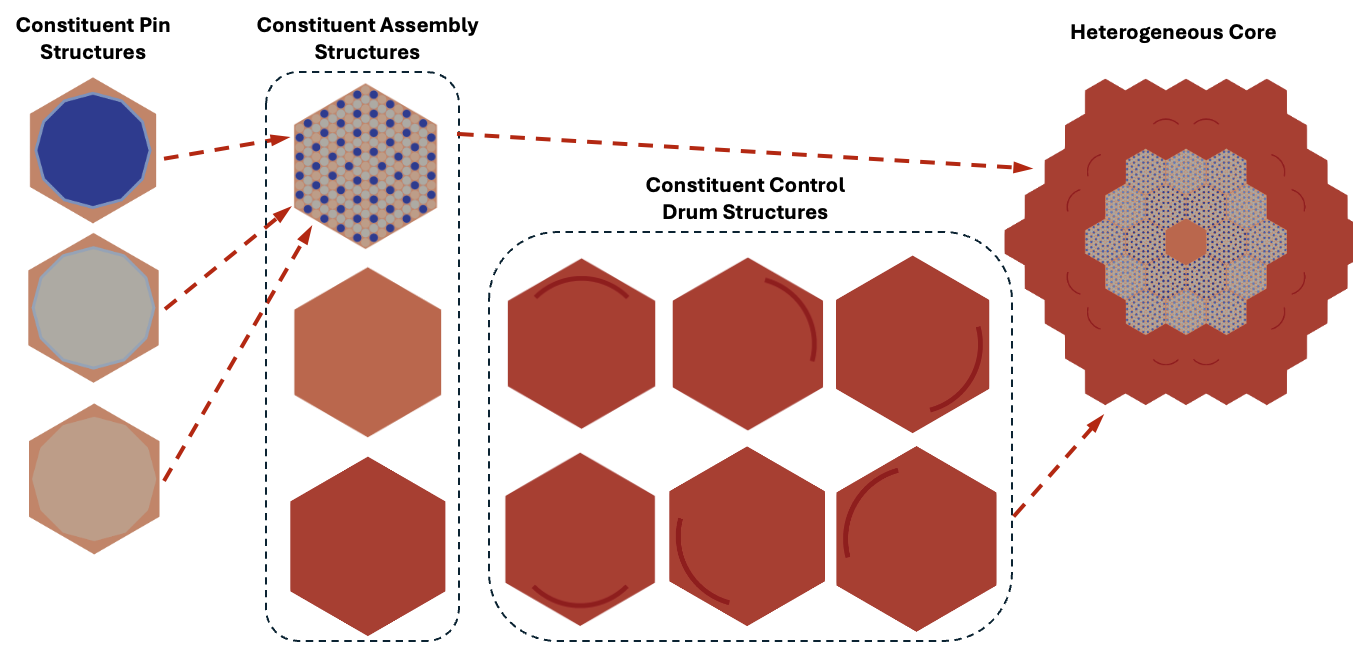
Figure 1: Visualization of meshing steps to build the 2D EMPIRE core mesh with RGMB.
ReactorMeshParams
ReactorMeshParams contains global mesh/geometry parameters including whether the final mesh is 2D or 3D, Cartesian or hexagonal, assembly pitch, and the axial discretization for the final extruded geometry. This information will be accessible to the other RGMB mesh generators and consistently used. Here we also invoke the option to enable flexible assembly stitching with "flexible_assembly_stitching", so that dissimilar assembly structures can be stitched into the reactor core without any hanging nodes. This parameter needs to be set to true in order to use ControlDrumMeshGenerator.
Listing 1: EMPIRE RGMB Reactor Mesh Parameters example.
[Mesh<<<{"href": "../../../syntax/Mesh/index.html"}>>>]
  [rmp]
    type = ReactorMeshParams<<<{"description": "This ReactorMeshParams object acts as storage for persistent information about the reactor geometry.", "href": "../../../source/meshgenerators/ReactorMeshParams.html"}>>>
    dim<<<{"description": "The dimension of the mesh to be generated"}>>> = 2 # Dimensionality of output mesh (2 or 3)
    geom<<<{"description": "The geometry type of the reactor mesh"}>>> = "Hex" # Geometry type (Hex or Square)
    assembly_pitch<<<{"description": "Center to center distance of assemblies"}>>> = 32.353 # Size of assembly flat-to-flat pitch
    radial_boundary_id<<<{"description": "The boundary ID to set on the outer radial boundary of a CoreMeshGenerator object"}>>> = 203 # Boundary id assigned to radial surface
    flexible_assembly_stitching<<<{"description": "Use FlexiblePatternGenerator for stitching dissimilar assemblies together"}>>> = true # Set to true to stitch dissimilar assembly types together,
    # i.e. homogeneous, heterogeneous, and control drum assemblies
    region_id_as_block_name<<<{"description": "Set block names based on region id"}>>> = true # Set this to true to assign block name based on the region ID
    # of the region. If quad and tri elements share the same region ID
    # two separate block names will be created
  []
[]Pin structures using PinMeshGenerator
The EMPIRE core features heterogeneous fuel assemblies, homogeneous air and reflector regions, and control drum structures all stitched into a hexagonal core lattice. We begin with defining the heterogeneous fuel assemblies.
PinMeshGenerator defines the constituent pin structures used for stitching into the fuel assemblies. The pin pitch, number of azimuthal sectors, and geometry / region ID information about each ring, background, and duct region are specified here.
PinMeshGenerator is called multiple times to define the various pin structures (3 fuel pin types, 1 heat pipe pin type, and 1 moderator pin type).
Listing 2: EMPIRE RGMB pin example.
[Mesh<<<{"href": "../../../syntax/Mesh/index.html"}>>>]
  [fuel_pin_1]
    type = PinMeshGenerator<<<{"description": "This PinMeshGenerator object is designed to generate pin-like structures, with IDs, from a reactor geometry. Whether it be a square or hexagonal pin, they are divided into three substructures - the innermost radial pin regions, the single bridging background region, and the square or hexagonal ducts regions.", "href": "../../../source/meshgenerators/PinMeshGenerator.html"}>>>
    reactor_params<<<{"description": "The ReactorMeshParams MeshGenerator that is the basis for this component conformal mesh."}>>> = rmp # Name of ReactorMeshParams object
    pin_type<<<{"description": "The integer ID for this pin type definition"}>>> = 1 # Unique identifier for pin type
    pitch<<<{"description": "The pitch for the outermost boundary polygon"}>>> = 2.15 # Pin pitch
    num_sectors<<<{"description": "Number of azimuthal sectors in each quadrant"}>>> = 2 # Number of azimuthal sectors per hexagonal side
    quad_center_elements<<<{"description": "Whether the center elements are quad or triangular."}>>> = false # Whether central mesh elements in inner ring should use
    # quad elements (true) or tri elements (false)
    ring_radii<<<{"description": "Radii of major concentric circles of the pin. If unspecified, no pin is present."}>>> = '0.925 0.975' # Radii for each ring
    mesh_intervals<<<{"description": "The number of meshing intervals for each region starting at the center. Parameter should be size:((length(ring_radii) + length(duct_halfpitch) + 1"}>>> = '3 1 1' # Number of radial intervals for each radial region
    # (inner ring, outer ring, background)
    region_ids<<<{"description": "IDs for each radial and axial zone for assignment of region_id extra element id. Inner indexing is radial zones (pin/background/duct), outer indexing is axial"}>>> = '${mid_fuel_1} ${mid_fgap} ${mid_ss}' # Region IDs for each radial region
    # (inner ring, outer ring, background)
  []
[]"region_ids" is a 2-dimensional array containing region IDs (essentially materials). Since this problem is 2-D and does not have any axial layers, we only need to define a single row of values corresponding to the 2D radial regions (from center of the pin to outermost region) of the pin. In this case, the fuel pin has 3 radial regions (fuel inner ring, gap outer ring, statinless steel background).
Assembly structures using AssemblyMeshGenerator
AssemblyMeshGenerator takes the pin types previously defined and places them into a regular hexagonal grid. Additionally, a stainless steel background region is added around the pins in order to create the assembly geometry.
AssemblyMeshGenerator is called multiple times to define the various heterogeneous assemblies (3 fuel assemblies).
Listing 3: EMPIRE RGMB heterogeneous assembly example.
[Mesh<<<{"href": "../../../syntax/Mesh/index.html"}>>>]
  [fuel_assembly_1]
    type = AssemblyMeshGenerator<<<{"description": "This AssemblyMeshGenerator object is designed to generate assembly-like structures, with IDs, from a reactor geometry. The assembly-like structures must consist of a full pattern of equal sized pins from PinMeshGenerator. A hexagonal assembly will be placed inside of a bounding hexagon consisting of a background region and, optionally, duct regions.", "href": "../../../source/meshgenerators/AssemblyMeshGenerator.html"}>>>
    assembly_type<<<{"description": "The integer ID for this assembly type definition"}>>> = 1 # Unique identifier for pin type
    background_intervals<<<{"description": "Radial intervals in the assembly peripheral region."}>>> = 1 # Number of radial intervals in background region
    background_region_id<<<{"description": "The region id for the background area between the pins and the ducts to set region_id extra-element integer"}>>> = '${mid_ss}' # Region ID corresponding to background region
    inputs<<<{"description": "The PinMeshGenerators that form the components of the assembly."}>>> = 'fuel_pin_1 hpipe_pin mod_pin' # Name of contituent pin mesh structures
    pattern<<<{"description": "A double-indexed array starting with the upper-left corner where the indexrepresents the layout of input pins in the assembly lattice."}>>> = '1 0 1 0 1 0 1 0 1;
              0 2 2 2 2 2 2 2 2 0;
             1 2 1 0 1 0 1 0 1 2 1;
            0 2 0 2 2 2 2 2 2 0 2 0;
           1 2 1 2 1 0 1 0 1 2 1 2 1;
          0 2 0 2 0 2 2 2 2 0 2 0 2 0;
         1 2 1 2 1 2 1 0 1 2 1 2 1 2 1;
        0 2 0 2 0 2 0 2 2 0 2 0 2 0 2 0;
       1 2 1 2 1 2 1 2 1 2 1 2 1 2 1 2 1;
        0 2 0 2 0 2 0 2 2 0 2 0 2 0 2 0;
         1 2 1 2 1 2 1 0 1 2 1 2 1 2 1;
          0 2 0 2 0 2 2 2 2 0 2 0 2 0;
           1 2 1 2 1 0 1 0 1 2 1 2 1;
            0 2 0 2 2 2 2 2 2 0 2 0;
             1 2 1 0 1 0 1 0 1 2 1;
              0 2 2 2 2 2 2 2 2 0;
               1 0 1 0 1 0 1 0 1' # Lattice pattern of constituent pins
  []
[]Use a unique AssemblyMeshGenerator block for each assembly with a unique geometrical configuration, region ID composition, and/or inventory of pin structures
"background_region_id" is a 1-dimensional array containing region IDs for each axial layer of the background region (since this is a 2-D mesh, only a single value needs to be provided).
Homogeneous assembly structures using PinMeshGenerator
In order to define homogeneous assembly structures to stitch into the core, we use PinMeshGenerator once again (AssemblyMeshGenerator is only used for structures that consist of lattices of pins).
To define single assemblies directly with PinMeshGenerators for stitching with CoreMeshGenerator, PinMeshGenerator is used with "use_as_assembly" set to
true.In addition, "homogenized" =
trueis used to indicate that this region is homogenized.
This process is repeated for each homogeneous assembly type (1 airhole assembly and 1 reflector assembly).
Listing 4: EMPIRE RGMB homogeneous assembly example.
[Mesh<<<{"href": "../../../syntax/Mesh/index.html"}>>>]
  [refl_assembly]
    type = PinMeshGenerator<<<{"description": "This PinMeshGenerator object is designed to generate pin-like structures, with IDs, from a reactor geometry. Whether it be a square or hexagonal pin, they are divided into three substructures - the innermost radial pin regions, the single bridging background region, and the square or hexagonal ducts regions.", "href": "../../../source/meshgenerators/PinMeshGenerator.html"}>>>
    reactor_params<<<{"description": "The ReactorMeshParams MeshGenerator that is the basis for this component conformal mesh."}>>> = rmp
    pin_type<<<{"description": "The integer ID for this pin type definition"}>>> = 5
    pitch<<<{"description": "The pitch for the outermost boundary polygon"}>>> = 32.353
    region_ids<<<{"description": "IDs for each radial and axial zone for assignment of region_id extra element id. Inner indexing is radial zones (pin/background/duct), outer indexing is axial"}>>> = '${mid_reflector}'
    homogenized<<<{"description": "Determines whether homogenized pin mesh should be generated"}>>> = true
    use_as_assembly<<<{"description": "Determines whether pin mesh should be used as an assembly mesh"}>>> = true
  []
[]For homogenized assemblies, each assembly has only 1 radial region, so a single value is passed to "region_ids" representing the region ID of the 2-D homogenized region.
Control drum structures using ControlDrumMeshGenerator
In order to define control drum structures to stitch into the core, we use ControlDrumMeshGenerator. "drum_inner_radius" and "drum_outer_radius" control the inner and outer radius of the drum region, while "drum_inner_intervals" and "drum_intervals" control the radial mesh density of the drum inner and drum regions respectively. "num_azimuthal_sectors" controls the azimuthal mesh density of the control drum structure.
Since we are interested in definining an explicit drum region for this structure, additional parameters are provided to ControlDrumMeshGenerator to specify this. "pad_start_angle" and "pad_end_angle" set the start and end angles of the drum pad region, where angles start in the positive y direction and rotate clockwise to indicate positive angles. Additionally, the "region_ids" parameter takes four values per axial layer, representing the four radial regions of the control drum structure (drum inner, drum pad, drum ex-pad, background)
This process is repeated for each control drum type. In this case, each unique control drum orientation is considered a separate type. Since we are generating 12 control drums with a total of 6 unique drum orientations, we create six control drum objects.
Listing 5: EMPIRE RGMB control drum example.
[Mesh<<<{"href": "../../../syntax/Mesh/index.html"}>>>]
  [cd_ne]
    type = ControlDrumMeshGenerator<<<{"description": "This ControlDrumMeshGenerator object is designed to generate drum-like structures, with IDs, from a reactor geometry. These structures can be used directly within CoreMeshGenerator to stitchcontrol drums into a core lattice alongside AssemblyMeshGenerator structures", "href": "../../../source/meshgenerators/ControlDrumMeshGenerator.html"}>>>
    assembly_type<<<{"description": "The assembly type integer ID to use for this control drum definition. This parameter should be uniquely defined for each ControlDrumMeshGenerator and AssemblyMeshGenerator structure in the RGMB workflow."}>>> = 6 # Unique identifier for assembly type
    reactor_params<<<{"description": "The ReactorMeshParams MeshGenerator that is the basis for this component mesh."}>>> = rmp # Name of ReactorMeshParams object
    drum_inner_radius<<<{"description": "Inner radius of drum region"}>>> = 13.8 # Inner radius of drum region
    drum_outer_radius<<<{"description": "Outer radius of drum region"}>>> = 14.8 # Outer radius of drum region
    num_azimuthal_sectors<<<{"description": "Number of azimuthal sectors to sub-divide the drum region into"}>>> = 72 # Number of azimuthal sectors for
    drum_inner_intervals<<<{"description": "Number of radial mesh intervals in region up to inner drum radius"}>>> = 15 # Number of radial intervals in drum inner region
    drum_intervals<<<{"description": "Number of radial mesh intervals in drum region"}>>> = 3 # Number of radial intervals in drum region
    pad_start_angle<<<{"description": "Starting angle of drum pad region"}>>> = 15 # Starting angle of drum pad region
    pad_end_angle<<<{"description": "Ending angle of drum pad region"}>>> = 105 # Ending angle of drum pad region
    region_ids<<<{"description": "IDs for each radial and axial zone for assignment of region_id extra element id. Inner indexing is radial zones (drum inner/drum/drum outer), outer indexing is axial"}>>> = '${mid_reflector} ${mid_drum_pad}
                  ${mid_reflector} ${mid_reflector}' # Region IDs of control drum region
    # (drum inner, drum pad, drum ex-pad, background)
  []
[]Heterogeneous core using CoreMeshGenerator
Now that all heterogeneous and homogeneous assemblies and control drum structures have been defined, they are placed into a lattice using CoreMeshGenerator. Since we have set "flexible_assembly_stitching" = true in ReactorMeshParams, RGMB will automatically take care of stitching these assembly types together by making sure the same number of nodes are defined on each interface of each assembly.
Listing 6: EMPIRE RGMB core example.
[Mesh<<<{"href": "../../../syntax/Mesh/index.html"}>>>]
  [core]
    type = CoreMeshGenerator<<<{"description": "This CoreMeshGenerator object is designed to generate a core-like structure, with IDs, from a reactor geometry. The core-like structure consists of a pattern of assembly-like structures generated with AssemblyMeshGenerator and/or ControlDrumMeshGenerator and is permitted to have \"empty\" locations. The size and spacing of the assembly-like structures is defined, and enforced by declaration in the ReactorMeshParams.", "href": "../../../source/meshgenerators/CoreMeshGenerator.html"}>>>
    inputs<<<{"description": "The AssemblyMeshGenerator and ControlDrumMeshGenerator objects that form the components of the assembly."}>>> = 'fuel_assembly_1 fuel_assembly_2
              fuel_assembly_3 airhole_assembly
              refl_assembly cd_ne cd_se cd_s cd_sw
              cd_nw cd_n' # Name of constituent assemblies
    pattern<<<{"description": "A double-indexed array starting with the upper-left corner where the indexrepresents the layout of input assemblies in the core lattice."}>>> = '4  4  4  4  4;
              4  4 10 10  4  4;
             4  9  1  2  1  5  4;
            4  9  2  0  0  2  5  4;
           4  4  1  0  3  0  1  4  4;
            4  8  2  0  0  2  6  4;
             4  8  1  2  1  6  4;
              4  4  7  7  4  4;
               4  4  4  4  4' # Lattice pattern of constituent assemblies

    # Define depletion IDs for each unique (pin, region_id) pair
    generate_depletion_id<<<{"description": "Determine wheter the depletion ID is assigned."}>>> = true
    depletion_id_type<<<{"description": "Determine level of details in depletion ID assignment."}>>> = pin
  []
[]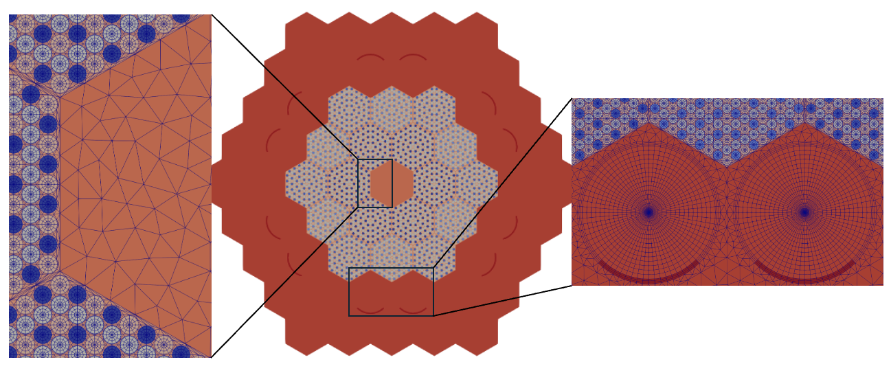
Figure 2: RGMB-generated 2D EMPIRE core mesh, colored by region ID.
Use of RGMB Mesh with Griffin
Griffin recognizes material ID assignments through the material_id tag. Therefore, the region_id tags need to be renamed to material_id. This is done using ExtraElementIDCopyGenerator.
Listing 7: EMPIRE material ID setup example.
[Mesh<<<{"href": "../../../syntax/Mesh/index.html"}>>>]
  [empire_mesh]
    type = ExtraElementIDCopyGenerator<<<{"description": "Copy an extra element ID to other extra element IDs.", "href": "../../../source/meshgenerators/ExtraElementIDCopyGenerator.html"}>>>
    input<<<{"description": "The mesh we want to modify"}>>> = core
    source_extra_element_id<<<{"description": "The extra element ID to be copied"}>>> = region_id
    target_extra_element_ids<<<{"description": "The target extra element IDs"}>>> = 'material_id'
  []
[]Material definition in the Griffin input file is then greatly simplified since material_id is defined directly on mesh. No additional mapping is needed.
Listing 8: Griffin materials setup.
[Materials<<<{"href": "../../../syntax/Materials/index.html"}>>>]
  [matid]
    type = MixedMatIDNeutronicsMaterial
    block = 'RGMB_CORE RGMB_CORE_TRI'
    isotopes = 'pseudo'
  []
[]RGMB labels outer boundary sidesets with pre-defined names – "top" for top boundary, "bottom" for bottom boundary, and "outer_core" for radial boundary. Boundary conditions are assigned to these sidesets in Griffin. Since this is a 2-D mesh, only the "outer_core" boundary sideset is created by RGMB.
Listing 9: Griffin Boundary conditions setup.
[TransportSystems]
  particle = neutron
  G = 6
  VacuumBoundary = 'outer_core'
  equation_type = eigenvalue
  [sn]
    scheme = DFEM-SN
    family = L2_LAGRANGE
    order = FIRST
    AQtype = Gauss-Chebyshev
    NPolar = 2
    NAzmthl = 3
    NA = 1
  []
[]References
- Christopher Matthews, Vincent Laboure, Mark DeHart, Joshua Hansel, David Andrs, Yaqi Wang, Javier Ortensi, and Richard C Martineau.
Coupled multiphysics simulations of heat pipe microreactors using direwolf.
Nuclear Technology, 207(7):1142–1162, 2021.[Export]