Thermal Hydraulics
MOOSE Modules for Thermal Hydraulics Modeling
MOOSE includes modules providing versatile, general-purpose thermal hydraulics capabilities. Collectively, these modules solve for mass, momentum, energy, and species conservation in multicomponent, multiphase flows using incompressible, weakly-compressible, or fully compressible formulations for steady-state or transient calculations in 1D, 2D, or 3D geometries. These capabilities range in fidelity and computational expense, as illustrated in Figure 1.
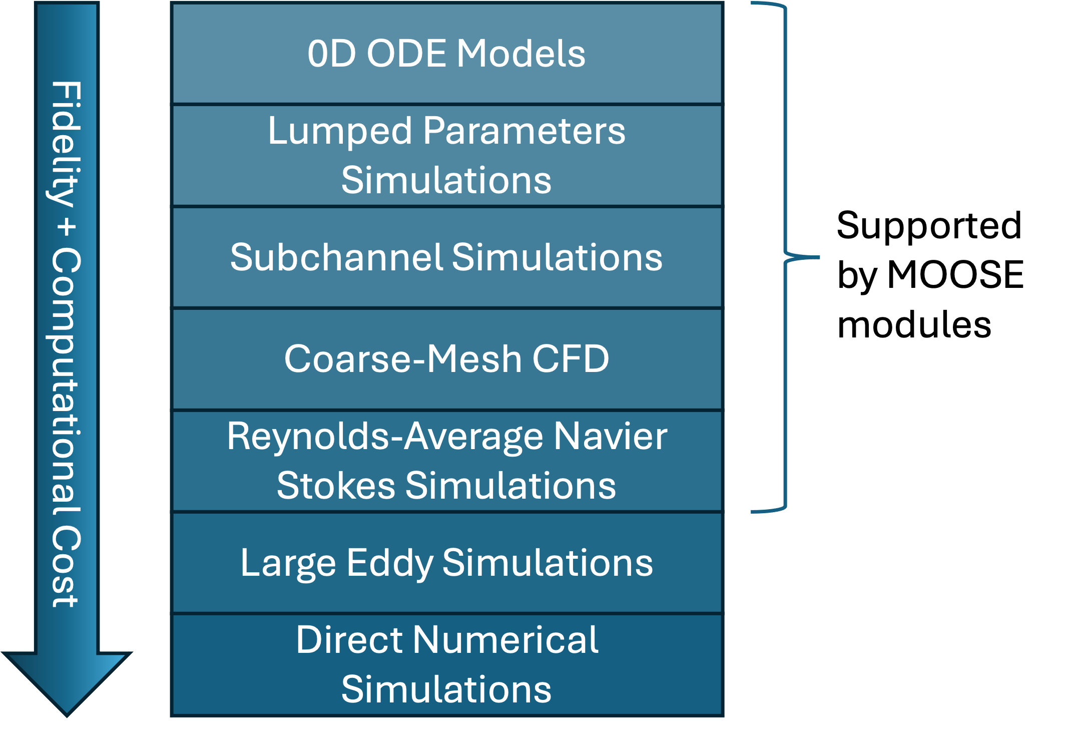
Figure 1: MOOSE modules support from Reynolds-Average Navier Stokes (RANS) Computational Fluid Dynamics (CFD) modeling to 0D lumped-parameters modeling.
The following table summarizes the MOOSE modules providing thermal hydraulics capabilities. The "Typical Runtime" column corresponds to a rough estimate of how much time it takes to run 100 time steps for a problem with the number of elements equal to the "Typical Element Count" value, using serial execution of the application.
| Module | Scale | Flow-Formulation | Dimension | Typical Element Count | Typical Runtime | Typical Simulations |
|---|---|---|---|---|---|---|
| Navier-Stokes | Coarse-Mesh CFD RANS simulations | Incompressible, Weakly-Compressible, or Fully-Compressible Single- or Multi-Phase Single- or Multi-Component Flow | Typically, 2D, 2D axisymmetric, or 3D Can also be used in 1D | 10,000 | 1 minute | Flow through nuclear reactor core or plena 3D multi-phase flow in pipes Natural convection flow in open cavities |
| Subchannel | Subchannel Scale | Incompressible or Weakly-Compressible Single-Phase Single- or Multi-Component Flow | 3D | 100,000 | 10 seconds | Flow development through nuclear reactor fuel assembly Thermal hydraulics analysis of nuclear reactor assembly blockage Natural convection cooling in nuclear reactors low-flow assemblies |
| Thermal Hydraulics | Lumped-Parameters Simulations | Compressible Single-Phase; Single-Component Flow | 1D, 0D | 100 | 10 seconds | Heat extraction unit from nuclear reactor core Thermal loops with significant compressibility effects |
| Porous Flow Module | Coarse-Mesh CFD | Incompressible, Weakly-Compressible, or Fully-Compressible Porous Flow (no inertial term) Single- or Multi-Phase Single- or Multi-Component Flow | Typically, 2D, 2D axisymmetric, or 3D Can also be used in 1D | 10,000 | 1 minute | Flow through fractured porous media Underground coal mining CO storage in saline aquifers |
MOOSE-Based Applications for Thermal Hydraulics Modeling
Here we note a selection of MOOSE-based thermal hydraulics applications, which are developed as part of the Nuclear Energy Advanced Modeling and Simulation (NEAMS) program. Some of these applications are open-source, whereas some are export-controlled and distributed via the Nuclear Computational Resource Center (NCRC); see NCRC Applications for more information.
| Application Name | Distribution | Based On | Added Features |
|---|---|---|---|
| Cardinal | Open-source | NekRS CFD | CPU and GPU capabilities for RANS, LES, and DNS. Additional features include Lagrangian particle transport, an ALE mesh solver, overset meshes, and more. |
| Pronghorn | NCRC | Navier-Stokes Module | Export-controlled correlations for pressure drop, heat exchange, and mass transfer in advanced nuclear reactors. |
| OpenPronghorn | Open-source | Navier-Stokes Module | Supplements Navier-Stokes Module module with validation and documentation, excludes export-controlled relations from Pronghorn. |
| SAM | NCRC | MOOSE Framework | Additional physics and component models for realistic plant modeling and reactor safety analysis. |
| RELAP-7 | NCRC | Thermal Hydraulics Module | Two-phase flow model and component models with additional closures appropriate for LWRs. |
| Sockeye | NCRC | Thermal Hydraulics Module | Adapted correlations and specific 1D and 2D models for high-temperature heat pipes. |
Examples Gallery
Molten Salt Reactors
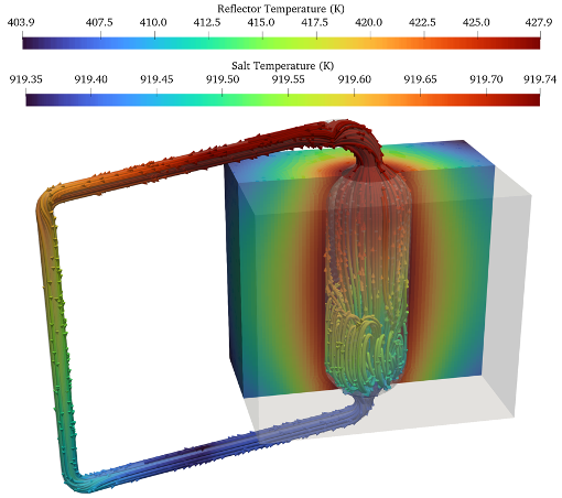
Figure 2: RANS simulation of conjugated heat transfer in a pool-type molten salt reactor concept using the MOOSE Navier-Stokes module.
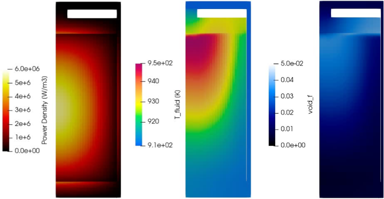
Figure 3: Power density (left), fuel temperature (center), and void fraction distribution (right) during the steady-state operation of the Molten Salt Reactor Experiment using the MOOSE Navier-Stokes module RANS simulation.
High Temperature Reactors
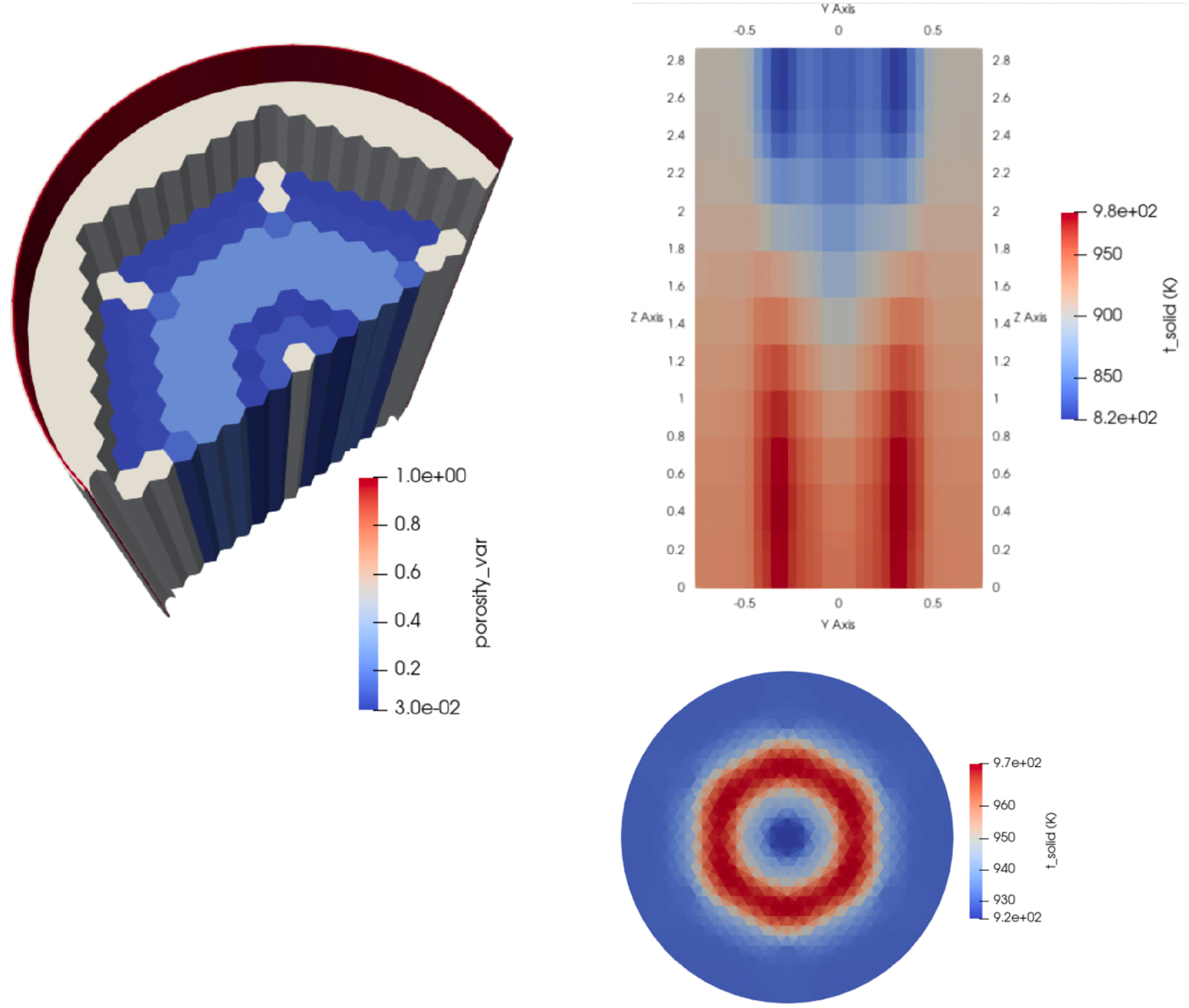
Figure 4: Steady-state operation of Oregon State University's High Temperature Test Facility (HTTF) using the MOOSE Navier-Stokes module coarse-mesh CFD capability.
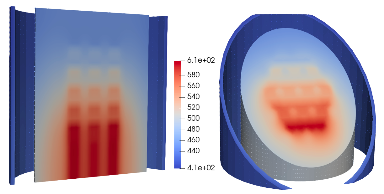
Figure 5: Temperature in fuel blocks of the High-Temperature Engineering Test Reactor (HTTR) during steady-state operation using the MOOSE Thermal Hydraulics Module (THM).
Liquid-Metal cooled Reactors
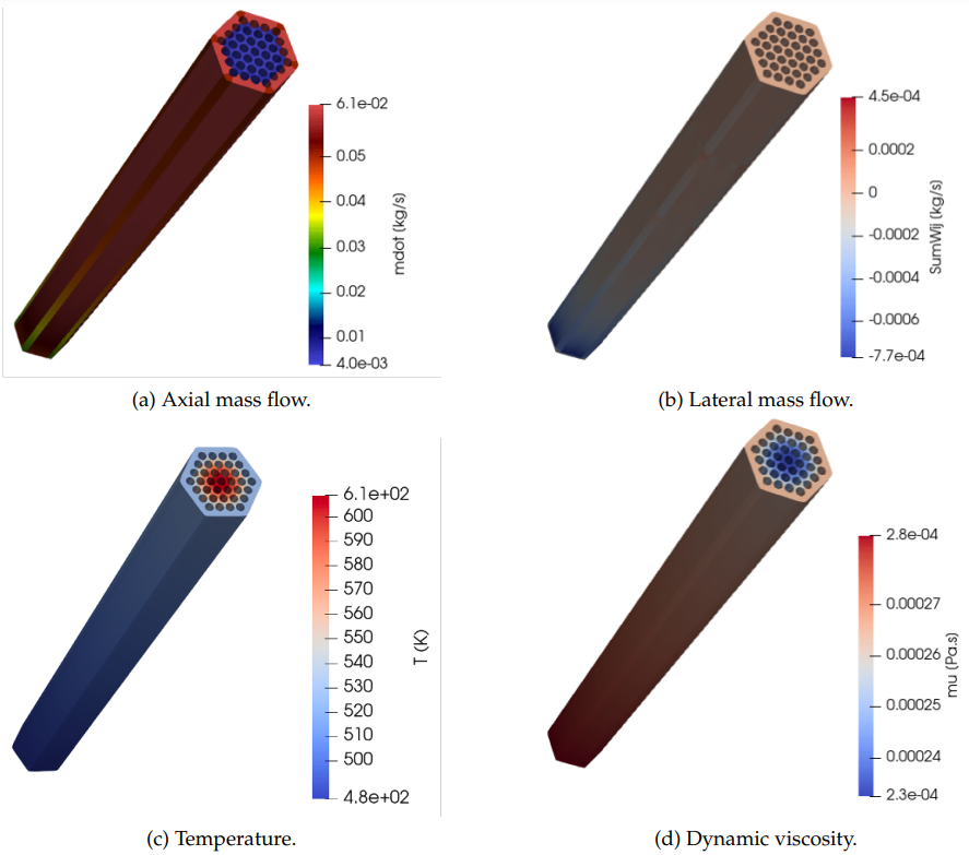
Figure 6: Steady-state operation of a fuel assembly in a liquid-metal-cooled reactor using the Subchannel Module.
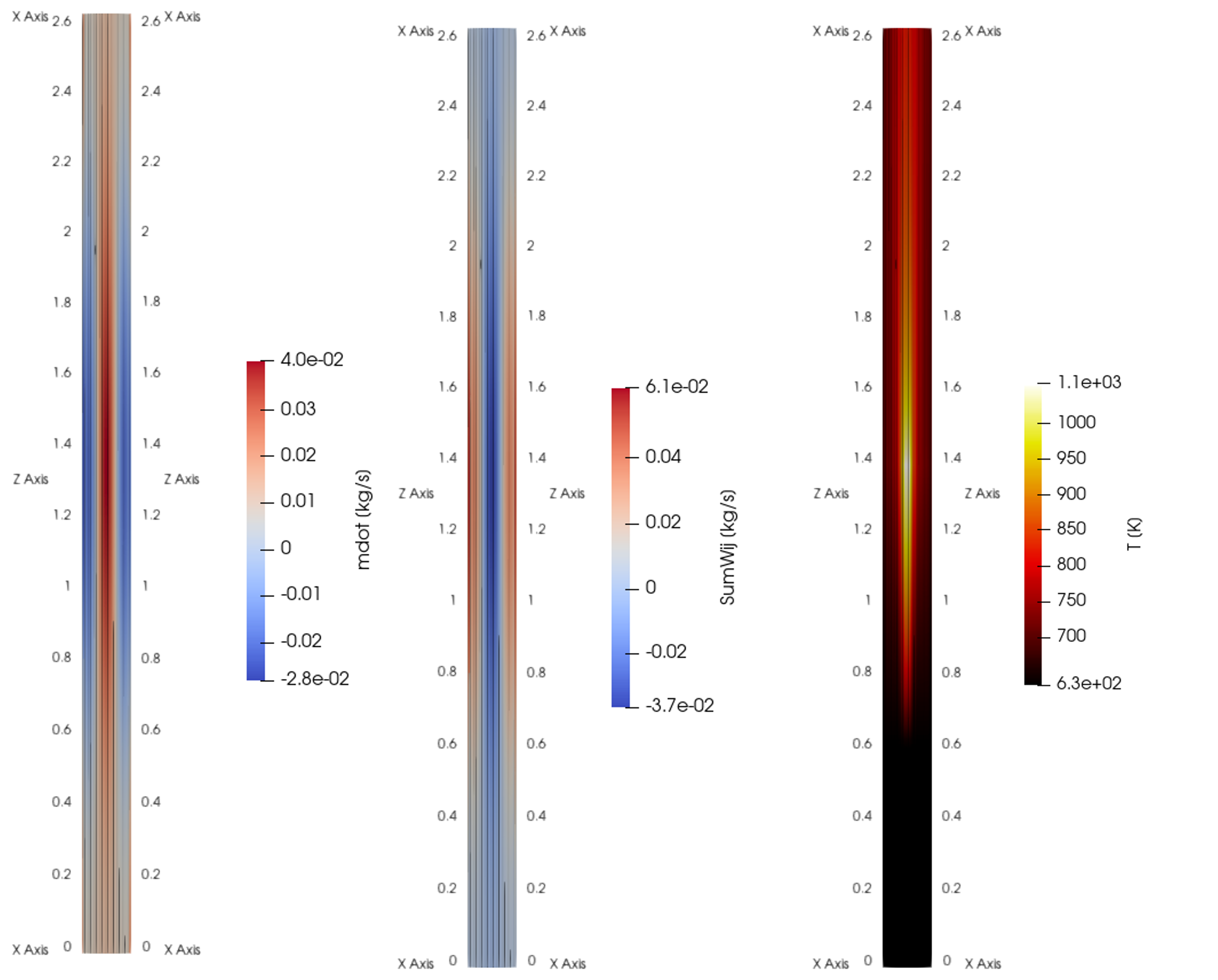
Figure 7: Simulation of internal recirculation in low-flow assemblies of a sodium-cooled fast reactor driven by natural convection, conducted using the Subchannel Module.
Two-Phase Flow
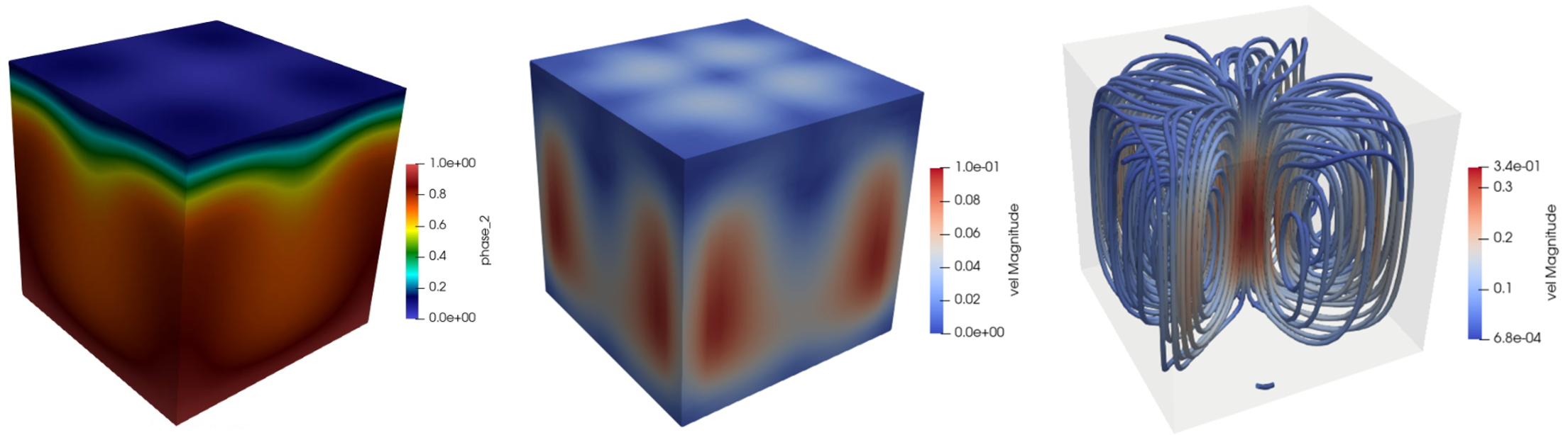
Figure 8: Two-phase Rayleigh-Benard convection in a 3D cavity using the drift-flux mixture model in the Navier-Stokes module, where the flow boils at the bottom plate and condenses at the top plate.
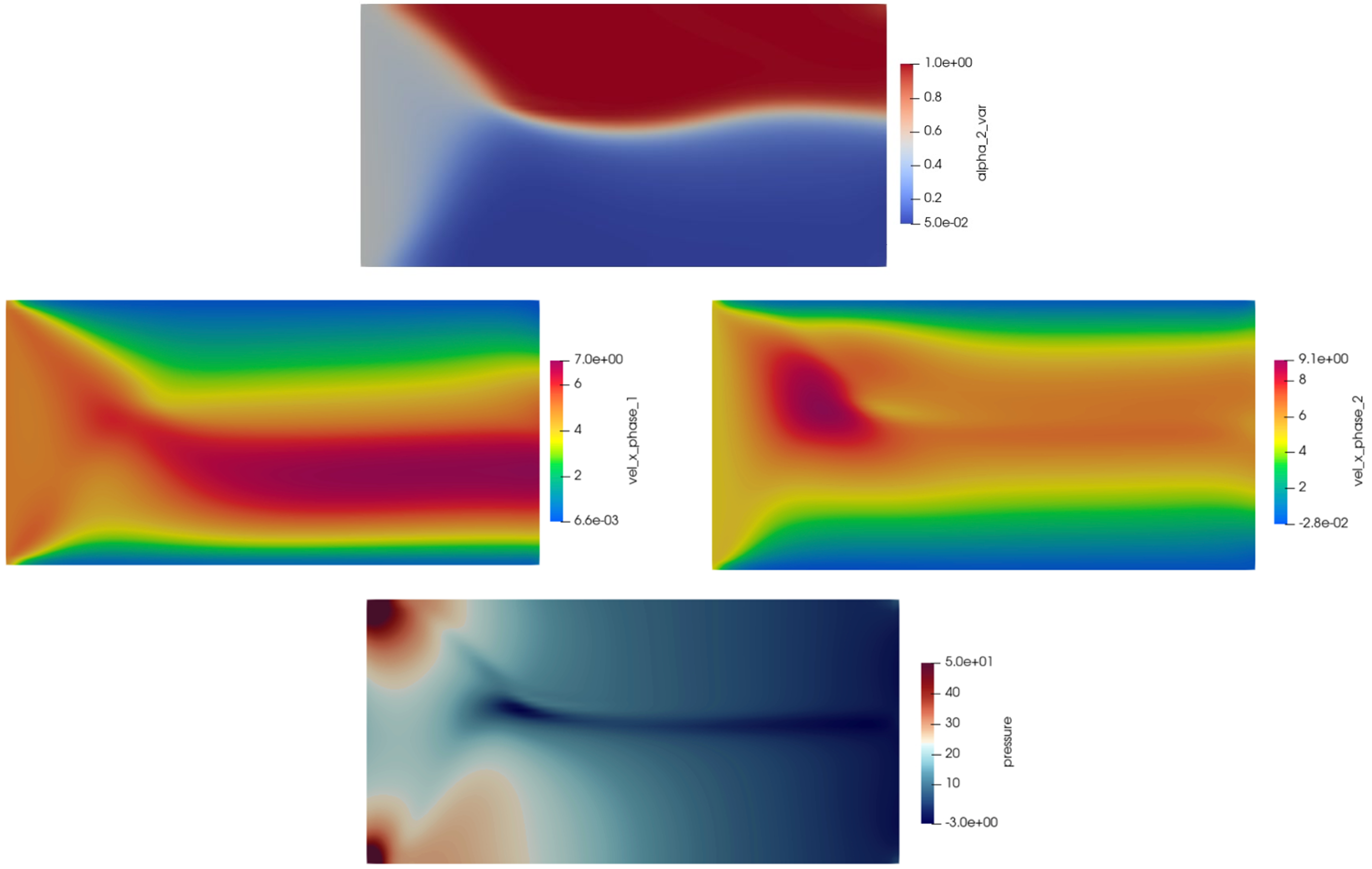
Figure 9: Two-phase flow stratification in a flow bed using the MOOSE Navier-Stokes module Euler-Euler capabilities, illustrating phase-fraction (top), phase-specific velocities (center), and pressure (bottom).
Laser Welding
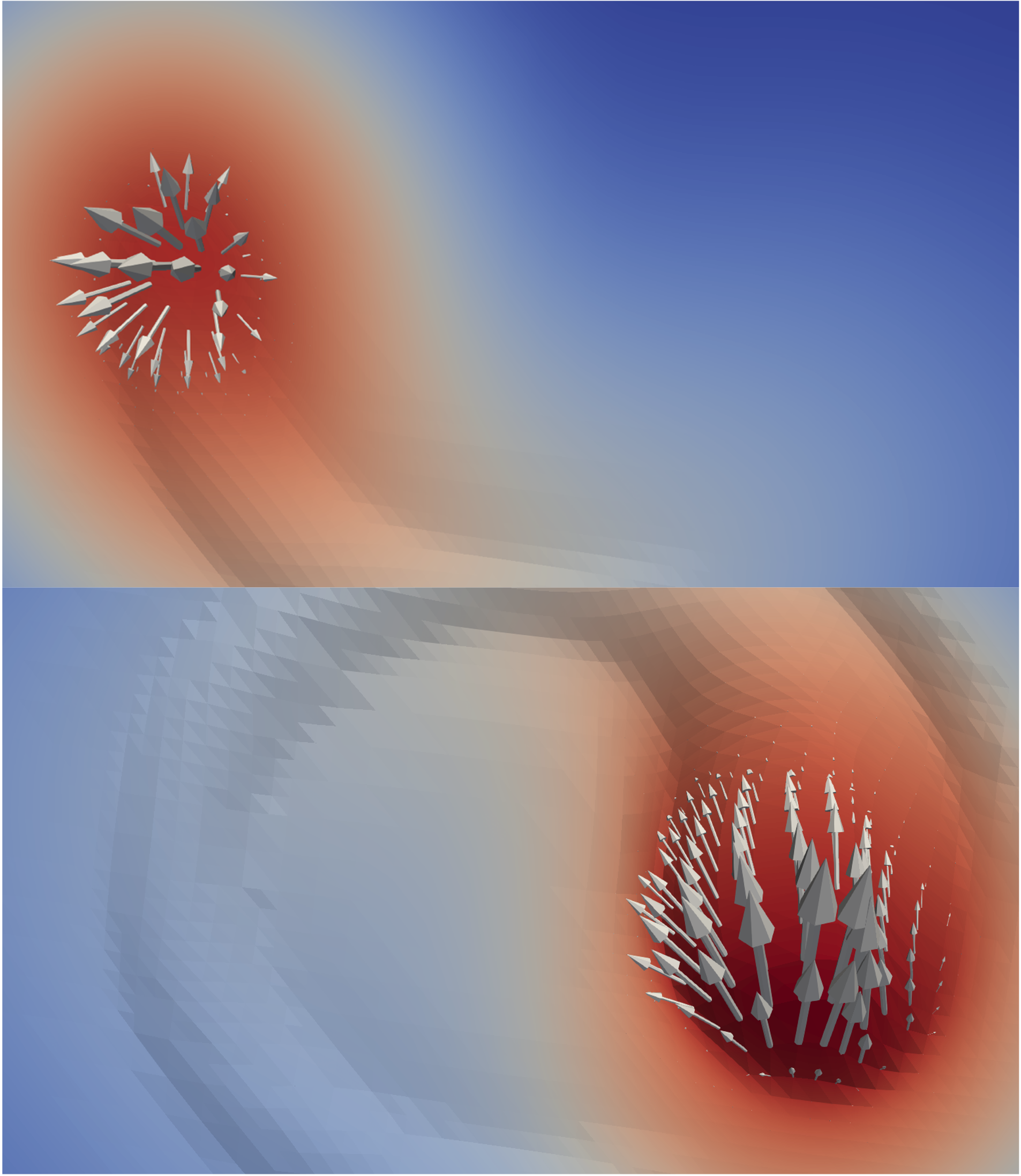
Figure 10: Melt-pool evaluation during laser welding, simulated using the MOOSE Navier-Stokes module.
Corrosion and Erosion
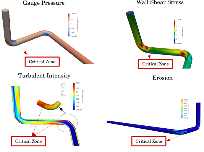
Figure 11: Prediction of critical spots for corrosion and erosion in a double-elbow pipe using the MOOSE Navier-Stokes module.