Reactor Geometry Mesh Builder Example: Conversion of Heterogeneous to Homogeneous Sodium-Cooled Fast Reactor Core Mesh (ABTR)
This example illustrates the use of RGMB mesh generators to define a pin-resolved heterogeneous 3D hexagonal geometry core for the Advanced Burner Test Reactor (ABTR) Shemon et al. (2015), and using Griffin to convert this mesh to an equivalent homogenized core mesh with automatic geometry construction and region ID assignment. The final mesh constructed will be similar to the one presented earlier in this tutorial using base mesh generators.
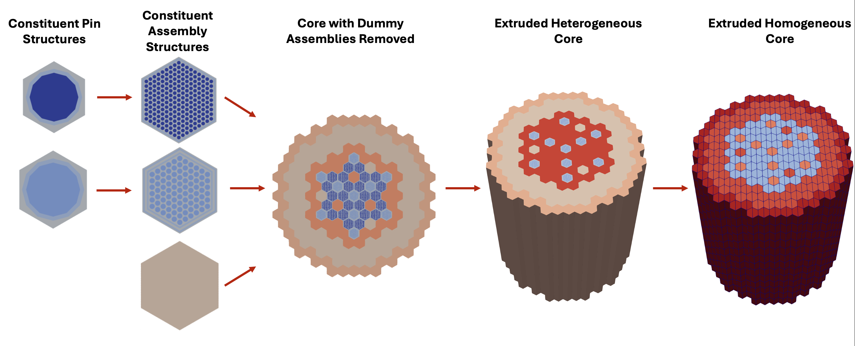
Figure 1: Visualization of meshing steps to build the 3D homogeneous ABTR core with RGMB and Griffin mesh generators.
ReactorMeshParams
ReactorMeshParams contains global mesh/geometry parameters including whether the final mesh is 2D or 3D, Cartesian or hexagonal, assembly pitch, and the axial discretization for the final extruded geometry. This information will be accessible to the other RGMB mesh generators and consistently used. Here we also invoke the option to enable flexible assembly stitching, so that dissimilar assembly structures can be stitched into the reactor core without any hanging nodes.
Listing 1: ABTR RGMB Reactor Mesh Parameters example.
[Mesh<<<{"href": "../../../syntax/Mesh/index.html"}>>>]
  [rmp]
    type = ReactorMeshParams<<<{"description": "This ReactorMeshParams object acts as storage for persistent information about the reactor geometry.", "href": "../../../source/meshgenerators/ReactorMeshParams.html"}>>>
    dim<<<{"description": "The dimension of the mesh to be generated"}>>> = 3 # Dimensionality of output mesh (2 or 3)
    geom<<<{"description": "The geometry type of the reactor mesh"}>>> = "Hex" # Geometry type (Hex or Square)
    assembly_pitch<<<{"description": "Center to center distance of assemblies"}>>> = ${assembly_pitch} # # Size of assembly flat-to-flat pitch

    axial_regions<<<{"description": "Length of each axial region"}>>> = '${dz_active_core_lower}
                     ${dz_active_core_upper}
                     ${dz_sodium_gp_upper}
                     ${dz_gp_upper}' # Size of each axial zone
    axial_mesh_intervals<<<{"description": "Number of elements in the Z direction for each axial region"}>>> = '${naxial_active_core_lower}
                            ${naxial_active_core_upper}
                            ${naxial_sodium_gp_upper}
                            ${naxial_gp_upper}' # Number of subintervals per axial zone
    top_boundary_id<<<{"description": "The boundary ID to set on top boundary of the extruded mesh"}>>> = 201 # Boundary ID assigned to top surface
    bottom_boundary_id<<<{"description": "The boundary ID to set on bottom boundary of the extruded mesh"}>>> = 202 # Boundary ID assigned to bottom surface
    radial_boundary_id<<<{"description": "The boundary ID to set on the outer radial boundary of a CoreMeshGenerator object"}>>> = 203 # Boundary ID assigned to radial surface
    flexible_assembly_stitching<<<{"description": "Use FlexiblePatternGenerator for stitching dissimilar assemblies together"}>>> = true # Set to true to stitch dissimilar assembly types together,
    # i.e. homogeneous and heterogeneous assemblies
  []
[]Pin structures using PinMeshGenerator
PinMeshGenerator defines the constituent pin structures used for stitching into assemblies. The pin pitch, number of azimuthal sectors, and geometry / region ID information about each ring, background, and duct region are specified here.
PinMeshGenerator is called multiple times to define the various pin structures (3 fuel pin types and 1 control pin type).
Listing 2: ABTR RGMB pin example.
[Mesh<<<{"href": "../../../syntax/Mesh/index.html"}>>>]
  [fuel_pin_1]
    type = PinMeshGenerator<<<{"description": "This PinMeshGenerator object is designed to generate pin-like structures, with IDs, from a reactor geometry. Whether it be a square or hexagonal pin, they are divided into three substructures - the innermost radial pin regions, the single bridging background region, and the square or hexagonal ducts regions.", "href": "../../../source/meshgenerators/PinMeshGenerator.html"}>>>
    reactor_params<<<{"description": "The ReactorMeshParams MeshGenerator that is the basis for this component conformal mesh."}>>> = rmp # Name of ReactorMeshParams object
    pin_type<<<{"description": "The integer ID for this pin type definition"}>>> = 1 # Unique identifier for pin type
    pitch<<<{"description": "The pitch for the outermost boundary polygon"}>>> = ${fuel_pin_pitch} # Pin pitch
    num_sectors<<<{"description": "Number of azimuthal sectors in each quadrant"}>>> = 2 # Number of azimuthal sectors per hexagonal side
    quad_center_elements<<<{"description": "Whether the center elements are quad or triangular."}>>> = false # Whether central mesh elements in inner ring should use
    # quad elements (true) or tri elements (false)
    ring_radii<<<{"description": "Radii of major concentric circles of the pin. If unspecified, no pin is present."}>>> = '${fuel_clad_r_i} ${fuel_clad_r_o}' # Radii for each ring
    mesh_intervals<<<{"description": "The number of meshing intervals for each region starting at the center. Parameter should be size:((length(ring_radii) + length(duct_halfpitch) + 1"}>>> = '1 1 1' # Number of radial intervals for each radial region
    # (inner ring, outer ring, background)
    region_ids<<<{"description": "IDs for each radial and axial zone for assignment of region_id extra element id. Inner indexing is radial zones (pin/background/duct), outer indexing is axial"}>>> = '${mid_lower_refl}     ${mid_lower_refl}     ${mid_lower_refl};
                  ${mid_fuel_1}         ${mid_ht9}            ${mid_sodium};
                  ${mid_upper_na_plen}  ${mid_upper_na_plen}  ${mid_upper_na_plen};
                  ${mid_upper_gas_plen} ${mid_upper_gas_plen} ${mid_upper_gas_plen}' # Region IDs for each radial region (inner ring, outer ring, background),
    # provided for each axial layer from bottom to top
  []
[]Use a unique PinMeshGenerator block for each pin with a unique geometrical configuration and/or region ID composition
"region_ids" is a 2-dimensional array containing region IDs (essentially materials). The first row of the array represents the 2D radial regions (from center of the pin to outermost region) for the bottom layer of the pin. Each subsequent row assigns IDs on another axial level, from bottom to top. In this case, each pin has 3 radial regions (fuel, clad, background), this array is a column pertaining to each axial level of the pin assembly.
While the mesh is still 2D during this step, the axially dependent region IDs are stored for later use during the extrusion step.
Assembly structures using AssemblyMeshGenerator
AssemblyMeshGenerator takes the pin types previously defined and places them into a regular hexagonal grid. Additionally, coolant and duct regions need to be added around the pins in order to create the assembly geometry.
AssemblyMeshGenerator is called multiple times to define the various heterogeneous assemblies (3 fuel assemblies and 1 control assembly).
Listing 3: ABTR RGMB heterogeneous assembly example.
[Mesh<<<{"href": "../../../syntax/Mesh/index.html"}>>>]
  [fuel_assembly_1]
    type = AssemblyMeshGenerator<<<{"description": "This AssemblyMeshGenerator object is designed to generate assembly-like structures, with IDs, from a reactor geometry. The assembly-like structures must consist of a full pattern of equal sized pins from PinMeshGenerator. A hexagonal assembly will be placed inside of a bounding hexagon consisting of a background region and, optionally, duct regions.", "href": "../../../source/meshgenerators/AssemblyMeshGenerator.html"}>>>
    assembly_type<<<{"description": "The integer ID for this assembly type definition"}>>> = 1 # Unique identifier for pin type

    background_intervals<<<{"description": "Radial intervals in the assembly peripheral region."}>>> = 1 # Number of radial intervals in background region
    background_region_id<<<{"description": "The region id for the background area between the pins and the ducts to set region_id extra-element integer"}>>> = '${mid_lower_refl}
                            ${mid_sodium}
                            ${mid_upper_na_plen}
                            ${mid_upper_gas_plen}' # Region ID corresponding to background region,
    # defined for each axial layer from bottom to top
    duct_halfpitch<<<{"description": "Distance(s) from center to duct(s) inner boundaries."}>>> = '${fparse duct_pitch_inner / 2}
                      ${fparse duct_pitch_outer / 2}' # Halfpitches for assembly inner and outer duct regions
    duct_intervals<<<{"description": "Number of meshing intervals in each enclosing duct."}>>> = '1 1' # Number of radial intervals for each assembly duct region
    duct_region_ids<<<{"description": "The region id for the ducts from innermost to outermost, to set region_id extra-element integer."}>>> = ' ${mid_lower_refl}     ${mid_lower_refl};
                        ${mid_ht9}            ${mid_sodium};
                        ${mid_upper_na_plen}  ${mid_upper_na_plen};
                        ${mid_upper_gas_plen} ${mid_upper_gas_plen}' # Region IDs corresponding to inner and outer duct regions,
    # defined for each axial layer from bottom to top

    inputs<<<{"description": "The PinMeshGenerators that form the components of the assembly."}>>> = 'fuel_pin_1' # Name of contituent pin mesh structures
    pattern<<<{"description": "A double-indexed array starting with the upper-left corner where the indexrepresents the layout of input pins in the assembly lattice."}>>> = '0 0 0 0 0 0 0 0 0;
              0 0 0 0 0 0 0 0 0 0;
             0 0 0 0 0 0 0 0 0 0 0;
            0 0 0 0 0 0 0 0 0 0 0 0;
           0 0 0 0 0 0 0 0 0 0 0 0 0;
          0 0 0 0 0 0 0 0 0 0 0 0 0 0;
         0 0 0 0 0 0 0 0 0 0 0 0 0 0 0;
        0 0 0 0 0 0 0 0 0 0 0 0 0 0 0 0;
       0 0 0 0 0 0 0 0 0 0 0 0 0 0 0 0 0;
        0 0 0 0 0 0 0 0 0 0 0 0 0 0 0 0;
         0 0 0 0 0 0 0 0 0 0 0 0 0 0 0;
          0 0 0 0 0 0 0 0 0 0 0 0 0 0;
           0 0 0 0 0 0 0 0 0 0 0 0 0;
            0 0 0 0 0 0 0 0 0 0 0 0;
             0 0 0 0 0 0 0 0 0 0 0;
              0 0 0 0 0 0 0 0 0 0;
               0 0 0 0 0 0 0 0 0' # Lattice pattern of constituent pins
  []
[]Use a unique AssemblyMeshGenerator block for each assembly with a unique geometrical configuration, region ID composition, and/or inventory of pin structures
"background_region_id" is a 1-dimensional array containing region IDs for each axial layer of the background region. "duct_region_ids" is a 2-dimensional array containing regions IDs for the duct region. The first row of the array represents the 2D duct regions (from innermost to outermost duct region) for the bottom layer of the assembly. Each subsequent row assigns IDs on another axial level, from bottom to top.
While the mesh is still 2D during this step, the axially dependent region IDs are stored for later use during the extrusion step.
Homogeneous assembly structures using PinMeshGenerator
In order to define homogeneous assembly structures to stitch into the core, we use PinMeshGenerator once again (AssemblyMeshGenerator is only used for structures that consist of lattices of pins).
To define single assemblies directly with PinMeshGenerators for stitching with CoreMeshGenerator, PinMeshGenerator is used with "use_as_assembly" set to
true.In addition, "homogenized" =
trueis used to indicate that this region is homogenized.
Listing 4: ABTR RGMB homogeneous assembly example.
[Mesh<<<{"href": "../../../syntax/Mesh/index.html"}>>>]
  [reflector_assembly]
    type = PinMeshGenerator<<<{"description": "This PinMeshGenerator object is designed to generate pin-like structures, with IDs, from a reactor geometry. Whether it be a square or hexagonal pin, they are divided into three substructures - the innermost radial pin regions, the single bridging background region, and the square or hexagonal ducts regions.", "href": "../../../source/meshgenerators/PinMeshGenerator.html"}>>>
    reactor_params<<<{"description": "The ReactorMeshParams MeshGenerator that is the basis for this component conformal mesh."}>>> = rmp # Name of ReactorMeshParams object
    pin_type<<<{"description": "The integer ID for this pin type definition"}>>> = 5 # Unique identiifier for assembly type
    pitch<<<{"description": "The pitch for the outermost boundary polygon"}>>> = ${assembly_pitch} # Assembly pitch
    homogenized<<<{"description": "Determines whether homogenized pin mesh should be generated"}>>> = true # Set to true to define homogenized mesh structure
    use_as_assembly<<<{"description": "Determines whether pin mesh should be used as an assembly mesh"}>>> = true # Set to true to treat output as assembly mesh structure, for stitching
    # directly into core lattice
    region_ids<<<{"description": "IDs for each radial and axial zone for assignment of region_id extra element id. Inner indexing is radial zones (pin/background/duct), outer indexing is axial"}>>> = '${mid_rad_refl};
                  ${mid_rad_refl};
                  ${mid_rad_refl};
                  ${mid_rad_refl}'
  []
[]For homogenized assemblies, each assembly has only 1 radial region, so each column in "region_ids" pertains to the region ID of each axial level of the homogenized assembly.
While the mesh is still 2D during this step, the axially dependent region IDs are stored for later use during the extrusion step.
Heterogeneous core using CoreMeshGenerator
Now that all heterogeneous and homogeneous assemblies have been defined, they are placed into a lattice using CoreMeshGenerator. While CoreMeshGenerator still requires a perfect hexagonal pattern like PatternedHexMeshGenerator, it automatically handles dummy assembly creation and deletion. The user need only provide a fake mesh input reference dummy (this object has not been actually created) and tell CoreMeshGenerator through the "dummy_assembly_name" parameter that the mesh input called dummy is a dummy assembly (empty space). The dummy assemblies will be created and deleted behind the scenes with no effort from the user.
Since we want to extrude the 2D core, we use the "extrude"=
trueparameter within CoreMeshGenerator. The step simultaneously extrudes the geometry and applies the regions IDs to all axial layers as defined in the PinMeshGenerator and AssemblyMeshGenerator objects.Behind the scenes, extra element IDs
assembly_idandplane_idare automatically added to the relevant elements.Since "flexible_assembly_stitching" =
truein ReactorMeshParams, the different assembly types are stitched together without hanging nodes.
Listing 5: ABTR RGMB core example.
[Mesh<<<{"href": "../../../syntax/Mesh/index.html"}>>>]
  [het_core]
    type = CoreMeshGenerator<<<{"description": "This CoreMeshGenerator object is designed to generate a core-like structure, with IDs, from a reactor geometry. The core-like structure consists of a pattern of assembly-like structures generated with AssemblyMeshGenerator and/or ControlDrumMeshGenerator and is permitted to have \"empty\" locations. The size and spacing of the assembly-like structures is defined, and enforced by declaration in the ReactorMeshParams.", "href": "../../../source/meshgenerators/CoreMeshGenerator.html"}>>>
    inputs<<<{"description": "The AssemblyMeshGenerator and ControlDrumMeshGenerator objects that form the components of the assembly."}>>> = 'fuel_assembly_1 fuel_assembly_2
              fuel_assembly_3 control_assembly
              reflector_assembly shielding_assembly
              dummy' # Name of constituent assemblies
    dummy_assembly_name<<<{"description": "The place holder name in \"inputs\" that indicates an empty position."}>>> = 'dummy' # Name of dummy assembly to
    # remove from core lattice pattern
    pattern<<<{"description": "A double-indexed array starting with the upper-left corner where the indexrepresents the layout of input assemblies in the core lattice."}>>> = '6 6 5 5 5 5 5 6 6;
              6 5 5 4 4 4 4 5 5 6;
             5 5 4 4 4 4 4 4 4 5 5;
            5 4 4 4 4 1 1 4 4 4 4 5;
           5 4 4 4 1 1 3 1 1 4 4 4 5;
          5 4 4 1 1 2 0 0 4 1 1 4 4 5;
         5 4 4 1 3 0 0 2 0 0 3 1 4 4 5;
        6 5 4 4 1 0 3 0 0 3 0 1 4 4 5 6;
       6 5 4 4 1 4 0 0 3 0 0 2 1 4 4 5 6;
        6 5 4 4 1 0 2 0 0 2 0 1 4 4 5 6;
         5 4 4 1 3 0 0 3 0 0 3 1 4 4 5;
          5 4 4 1 1 2 0 0 4 1 1 4 4 5;
           5 4 4 4 1 1 3 1 1 4 4 4 5;
            5 4 4 4 4 1 1 4 4 4 4 5;
             5 5 4 4 4 4 4 4 4 5 5;
              6 5 5 4 4 4 4 5 5 6;
               6 6 5 5 5 5 5 6 6' # Lattice pattern of constituent assemblies
    extrude<<<{"description": "Determines if this is the final step in the geometry construction and extrudes the 2D geometry to 3D. If this is true then this mesh cannot be used in further mesh building in the Reactor workflow"}>>> = true # Extrude core to 3-D
  []
[]"extrude" = true indicates extrusion should happen at this step (this should only be set to true once in the entire input file)
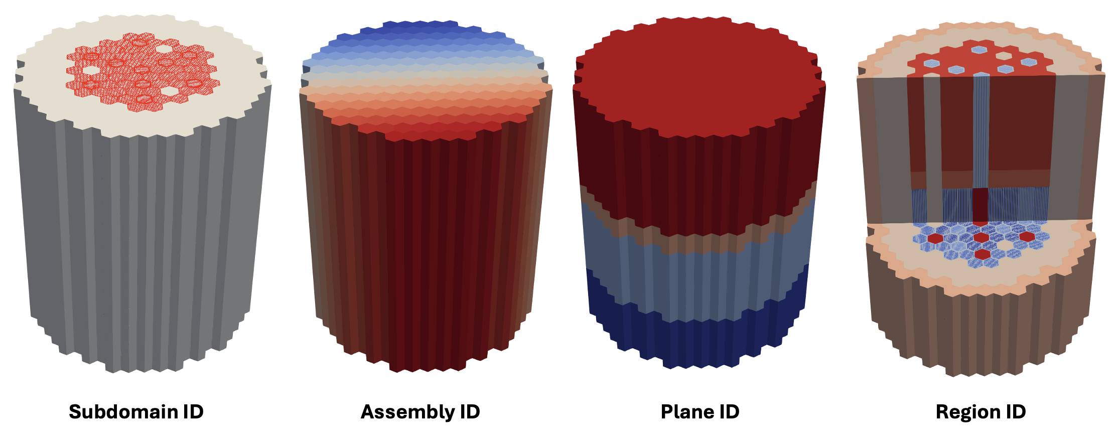
Figure 2: RGMB-generated 3D heterogeneous core mesh, colored by various IDs defined on the mesh.
Equivalent homogeneous core using Griffin's EquivalentCoreMeshGenerator
This section assumes the user has access to the Griffin executable, as it invokes EquivalentCoreMeshGenerator that is defined within Griffin.
So far, a 3-D heterogeneous pin-resolved hexagonal ABTR core geometry has been created exlusively using the Reactor Geometry Mesh Builder defined in the MOOSE Reactor module. This section requires the use of EquivalentCoreMeshGenerator defined in the Griffin code. This mesh generator defined in Griffin converts an input heterogeneous RGMB mesh into equivalent "duct heterogeneous", "ring heterogeneous", or "fully homogeneous" representations. Each unique subassembly region (radial + axial location) will have its own region ID in the equivalent core mesh.
In this case,
EquivalentCoreMeshGeneratorwill determine uniqueness based on both the geometry AND region ID mapping of each subassembly region in the heterogeneous core.
Listing 6: Conversion of ABTR RGMB heterogeneous core to homogeneous core in Griffin
[Mesh<<<{"href": "../../../syntax/Mesh/index.html"}>>>]
  [hom_core]
    type = EquivalentCoreMeshGenerator
    input = het_core # Name of input heterogeneous mesh
    target_geometry = full_hom # Target geometry type for
    # equivalent core mesh generation
    # (options are full_hom, duct_het, and ring_het)
    quad_center_elements = true # Whether output homogeneous should
    # be defined using quad elements (true)
    # or tri elements (false)
  []
[]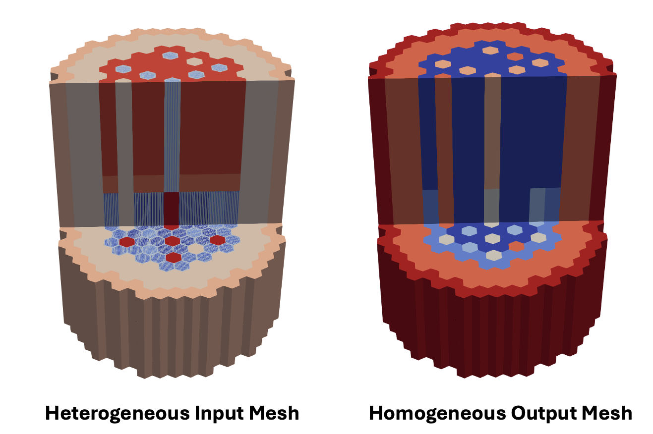
Figure 3: Side-by-side comparison of RGMB-generated heterogeneous core mesh (left) and Griffin-generated equivalent homogeneous core mesh (right), colored by region ID
Use of EquivalentCoreMeshGenerator Mesh with Griffin
EquivalentCoreMeshGenerator will define the same reporting IDs used by RGMB. In addition, EquivalentCoreMeshGenerator will automatically copy the "region_id" reporting ID to the "material_id" reporting ID, since Griffin recognizes material ID assignments through the material_id tag.
Material definition in the Griffin input file is then greatly simplified since material_id is defined directly on mesh. No additional mapping is needed.
Listing 7: Griffin materials setup.
[Materials<<<{"href": "../../../syntax/Materials/index.html"}>>>]
  [matid]
    type = MixedMatIDNeutronicsMaterial
    block = 'RGMB_CORE'
    isotopes = 'pseudo'
  []
[]EquivalentCoreMeshGenerator and RGMB label outer boundary sidesets for core structures with pre-defined names – "top" for top boundary, "bottom" for bottom boundary, and "outer_core" for radial boundary. Boundary conditions are assigned to these sidesets in Griffin.
Listing 8: Griffin Boundary conditions setup.
[TransportSystems]
  particle = neutron
  G = 33
  VacuumBoundary = 'outer_core top bottom'
  equation_type = eigenvalue
  [sn]
    scheme = DFEM-SN
    family = L2_LAGRANGE
    order = FIRST
    AQtype = Gauss-Chebyshev
    NPolar = 2
    NAzmthl = 3
    NA = 1
  []
[]References
- E. R. Shemon, J. J. Grudzinski, C. H. Lee, J. W. Thomas, and Y. Q. Yu.
Specification of the advanced burner test reactor multi-physics coupling demonstration problem.
Technical Report ANL/NE-15/43, Argonne National Laboratory, 12 2015.
URL: https://www.osti.gov/biblio/1236452, doi:10.2172/1236452.[Export]