MOOSE Reactor Module Tutorial: Meshing Reactor Geometries
Contents
Reactor Module Overview
Building the Reactor Module
Meshing Workflow in MOOSE
Meshing Terminology
Frequently Used Reactor Geometries and Corresponding Mesh Generators
Frequently Used Operations and Corresponding MeshGenerators
Reporting IDs: A Powerful Feature for Assisting with Physics Input and Output Processing
Example: Homogenous Assembly Fast Reactor Core (ABTR)
Example: Heat Pipe-Cooled Micro Reactor (HP-MR)
Reactor Geometry Mesh Builder (RGMB): A Contained System for Building Regular Geometries
RGMB Example: Heterogeneous to Homogeneous Conversion for Fast Reactor Core (ABTR)
RGMB Example: 2-D Empire Microreactor Core Mesh with Control Drum Stitching
Advanced Meshing Tools
Advanced Meshing Examples
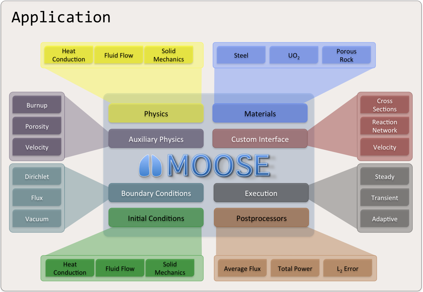
MOOSE
Multi-physics Object Oriented Simulation Environment
mooseframework.inl.gov

History and Purpose
Development started in 2008
Open-sourced in 2014
Designed to solve computational engineering problems and reduce the expense and time required to develop new applications by:
Being easily extended and maintained
Working efficiently on a few and many processors
Providing an object-oriented, extensible system for creating all aspects of a simulation tool
Motivated by multiphysics problems in nuclear engineering, but applications have extended into diverse fields
Core team at Idaho National Laboratory, but with significant contributions from other laboratories, universities, and industry, both domestically and internationally
By The Numbers
250 contributors
58,000 commits
5,000 unique visitors per month
~40 new Discussion participants per week
150M tests per week
General Capabilities
Continuous and Discontinuous Galerkin FEM
Finite Volume
Supports fully coupled or segregated systems, fully implicit and explicit time integration
Automatic differentiation (AD)
Unstructured mesh with FEM shapes
Higher order geometry
Mesh adaptivity (refinement and coarsening)
Massively parallel (MPI and threads)
User code agnostic of dimension, parallelism, shape functions, etc.
Native support for executing multiphysics simulations across applications
GPU support for execution via MFEM and Kokkos
Operating Systems:
macOS (Conda, Docker)
Linux (Apptainer, Conda, Docker)
Windows (Docker, WSL)
Object-oriented, pluggable system
Example Code

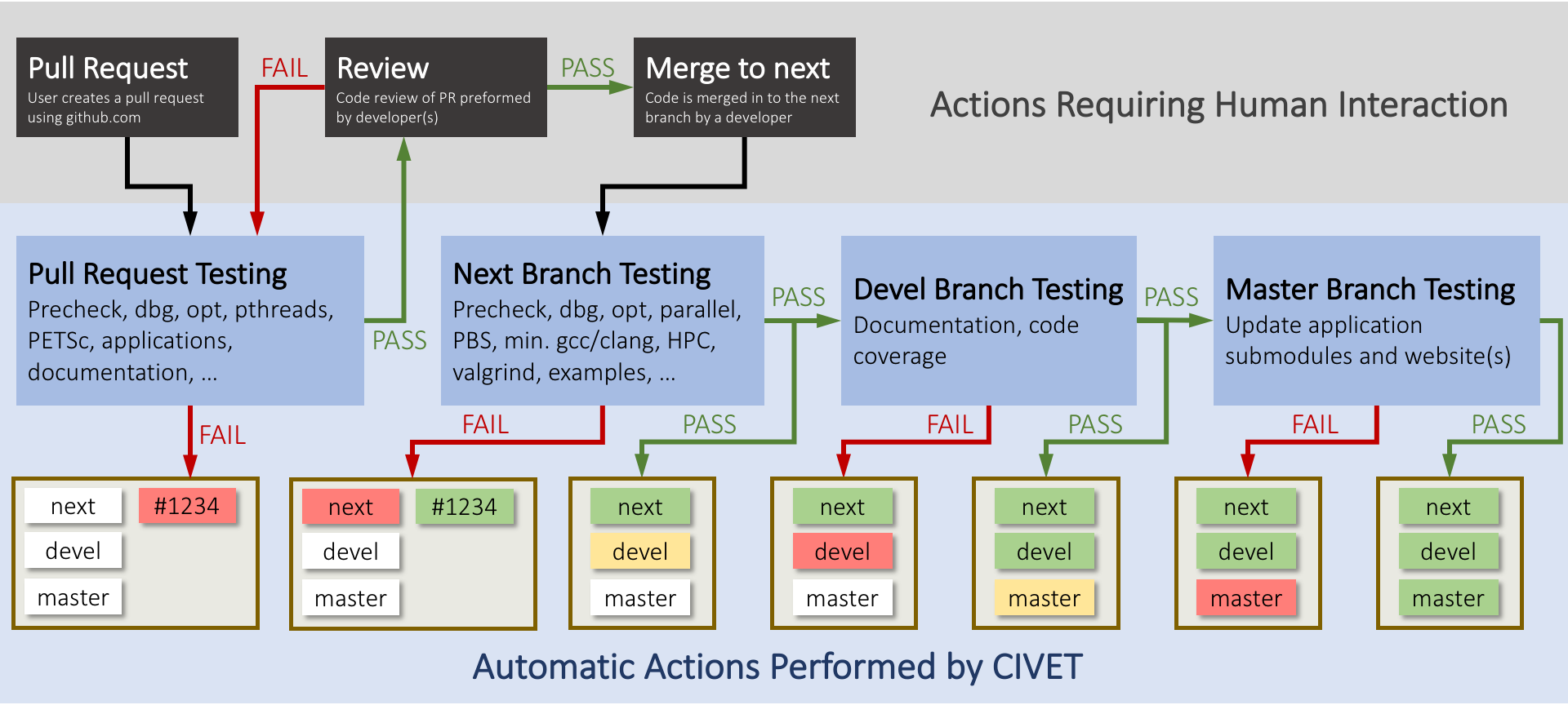
Software Quality
Follows a Nuclear Quality Assurance Level 1 (NQA-1) development process
All changes undergo independent review and must pass regression tests before merge
Includes a test suite and documentation system to allow for agile development while maintaining a NQA-1 process
External contributions are guided through the process by the team, and are very welcome!
Development Process
Community
github.com/idaholab/moose/discussions

License
LGPL 2.1
Does not limit what you can do with your application
Can license/sell your application as closed source
Modifications to the library itself (or the modules) are open source
New contributions are automatically LGPL 2.1
Reactor Module Overview
Introduction
MOOSE's Reactor Module provides targeted meshing capability for common nuclear reactor core geometries
Rapidly build reactor pins, assemblies, and cores and perform operations like extrusion, rotation, and triangulation
Create rotating control drums and core periphery zones (outer barrel / shield)
Automatically preserve fuel pin volume
Apply boundary layers, mesh biasing, slicing, adaptive meshing to match other meshes
Automatic label of elements by component (e.g. pin, assembly, plane)
How it works, in a nutshell
The Reactor Module contains mesh generation objects which a user calls from the
[Mesh]block of a MOOSE input fileUser constructs sequences of mesh generation objects to build custom Cartesian and hexagonal-based pins, assemblies, and cores
Meshes may be created in memory or pre-generated/output as Exodus files for later use
MOOSE Meshing vs External Tools
MOOSE's Reactor Module offers several benefits over commonly used meshing software for many supported geometries:
Free and open source (included with MOOSE, no additional software packages needed)
Tightly integrated with MOOSE-based applications (link mesh and physics input to same input and executable)
Specialized functions for reactor geometries
Component/zone bookkeeping through "extra element integers" for material assignment and post-processing
Automatic fuel volume preservation useful for mesh convergence studies
Saves analyst and computer time – easier to learn than generic FEM tools and runs quickly
The Reactor Module is currently best suited for extruded and rotated geometries. It is not intended for complex components such as heat exchangers, 3D meshing of inlet plenums, CAD geometries, or wire-wrapped pins. However, tetrahedral meshing algorithms are in the progress of being added.
Reactor Module Examples
The Reactor Module has been used to mesh cores of several reactor types:
liquid metal-cooled fast reactor (SFR, LFR)
heat pipe-cooled microreactor (HP-MR)
gas-cooled microreactor (GC-MR)
prismatic high temperature gas cooled reactor (prismatic HTGR) core geometries
Additionally, advanced meshing routines can be used to mesh some types of molten salt reactor (MSR) and pebble bed HTGR (PB-HTGR) cores.
The following meshes were generated by MOOSE's Reactor Module + Mesh System.
C5G7 Light Water Reactor
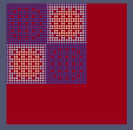
Figure 5: C5G7 light water reactor benchmark (Courtesy Yeon Sang Jung, Argonne National Laboratory).
Lead-Cooled Fast Reactor
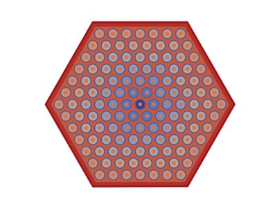
Figure 6: Lead-cooled fast reactor assembly with annular pins (Credit: Emily Shemon, Shikhar Kumar, Hansol Park, Argonne National Laboratory).
Advanced Burner Test Reactor

Figure 7: Advanced Burner Test Reactor (ABTR) (Credit Shikhar Kumar, Argonne National Laboratory).
MARVEL Microreactor
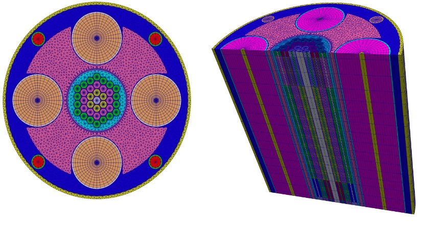
Figure 8: DOE-NE MARVEL microreactor concept at Idaho National Laboratory (Courtesy Stefano Terlizzi, Idaho National Laboratory).
High Temperature Gas-Cooled Reactor
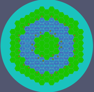
Figure 9: Modular High Temperature Gas-Cooled Reactor (MHTGR) (Courtesy Olin Calvin, Idaho National Laboratory).
Molten Salt Reactor Experiment
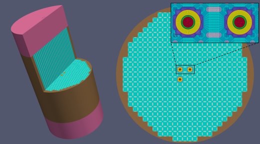
Figure 10: Molten Salt Reactor Experiment at Oak Ridge National Laboratory (Courtesy Kun Mo and Yan Cao, Argonne National Laboratory).
Building the Reactor Module
Install MOOSE
To use the Reactor Module you must first Install MOOSE.
In this tutorial, $MOOSE_DIR is defined as the MOOSE installation directory. This can be set in a Bash shell like this (assuming you installed in ~/projects/moose):
export $MOOSE_DIR=~/projects/moose
The copy/paste commands in this tutorial expect you will have this environment variable defined.
Compiling an app
Compile the Reactor Module App by navigating to $MOOSE_DIR/modules/reactor and issuing the make command. This will generate a binary file (reactor-opt) in that directory which leverages both the MOOSE framework and Reactor module capabilities. Running the binary with the --version flag should simply output the current code version without error if it was compiled properly.
cd $MOOSE_DIR/modules/reactor
make -j4
./reactor-opt --version
To test that a compiled binary is linked properly with the Reactor module, the binary can be run with one of the Reactor module test inputs:
$MOOSE_DIR/modules/reactor/reactor-opt -i $MOOSE_DIR/modules/reactor/test/tests/meshgenerators/simple_hexagon_generator/sim_hex.i --mesh-only
This should output generated mesh information without producing any errors.
Meshing Workflow in MOOSE
Constructing a Reactor Mesh Hierarchically
MOOSE's Mesh System and Reactor Module contains numerous "MeshGenerator" objects which either (a) create a mesh from scratch or (b) perform operations on existing meshes. To create a mesh, the user must define a sequence of MeshGenerator object calls inside the [Mesh] block to construct a geometry beginning with the smallest components (pins) and building up to larger components (core). For example, after pins are defined, they can be patterned into an assembly, and assemblies can then be patterned into a core. Application of a peripheral core zone, trimming along symmetry lines and extrusion to 3D are optional in the final steps.
The meshing workflow for a standard reactor core follows the general hierarchical process of identifying key features in the geometry and building them hierarchically in terms of smallest to largest (pins, assemblies, core, core periphery):
Define pins
Define assembly by patterning existing pins into a lattice and adding coolant background and/or duct region
Define core by patterning assemblies into a lattice
Apply core periphery zones like a circular shield
Trim along lines of symmetry to reduce computational expense
Extrude to 3D
Execution
Use any executable with the Reactor module compiled, such as or $MOOSE_DIR/modules/reactor-opt along with the --mesh-only command line option:
$MOOSE_DIR/modules/reactor/reactor-opt -i <my_meshing_input.i> --mesh-only
The --mesh-only optional command line parameter executes only the [Mesh] block of the input file and outputs the generated mesh. This is useful while building and testing the mesh as it doesn't require the rest of the MOOSE problem be defined in the input file. Recent updates to the --mesh-only option now allow the mesh output in Exodus format to include the extra element integer IDs defined on the mesh by default for convenient visualization purposes.
When you are satisfied with your mesh input, you may invoke MOOSE without the --mesh-only option to execute the entire input file (mesh building and physics input).
Executables of any MOOSE applications that contain the Reactor module in their Makefile can also be used, such as Griffin, Sockeye, Pronghorn, Cardinal, and BlueCRAB.
Visualization with ParaView
The Exodus output format is the preferred way to write out simulation results from MOOSE simulations. This format is supported by ParaView, VisIt, and other postprocessing applications. ParaView is most commonly used, but the visualization procedure is similar for other programs.
To save a lot of clicks, the following settings are recommended (in Edit->Settings):
Auto Apply: Automatically apply changes in the 'Properties' panel
Load All Variables: Load all variables when loading a data set
Default Time Step: Go to last timestep
](../../../../large_media/tutorials/tutorial04_meshing/paraview-defaults.png)
Figure 11: Recommended default settings in ParaView. Ahrens et al. (2005)
To visually inspect a mesh, first load the Exodus output file (ending in .e) into ParaView. Select the Open button in the top left corner, browse to the Exodus mesh file, click OK, and click the Apply button in the Properties dialogue in the lower left corner.
](../../../../large_media/tutorials/tutorial04_meshing/paraview-open.png)
Figure 1: Open Exodus mesh file in ParaView. Ahrens et al. (2005)
With the mesh loaded, there are two key visualization options in the top center of the menu: the visualization style on the right, which is good to set to Surface with Edges to show where the element boundaries are located, and the visualization property on the left, which can be switched between the various properties defined on the mesh.
](../../../../large_media/tutorials/tutorial04_meshing/paraview-vis-selectors.png)
Figure 2: ParaView visualization selectors. Ahrens et al. (2005)
There are also a variety of toggles in the Properties dialog in the lower left corner, which can control which elements of the mesh are visualized. After any modification of the properties, be sure to click Apply for the changes to apply.
](../../../../large_media/tutorials/tutorial04_meshing/paraview-properties.png)
Figure 3: ParaView properties dialogue. Ahrens et al. (2005)
In this example, the periphery block was removed and outer core side set is highlighted (in green).
](../../../../large_media/tutorials/tutorial04_meshing/paraview-example.png)
Figure 4: Example of selected blocks/sidesets. Ahrens et al. (2005)
Meshing Terminology
Before proceeding in this tutorial, we briefly define some terminology, limiting discussion to the spatial domain for simplicity:
Finite Element Method (FEM)
A numerical technique to solve PDEs which first requires that the spatial domain be divided into a mesh consisting of a finite number of discretized pieces. (FEM is one of the foundations of the MOOSE framework.)
Mesh
A set of points connected to form a network which discretize a geometry into discrete elements.
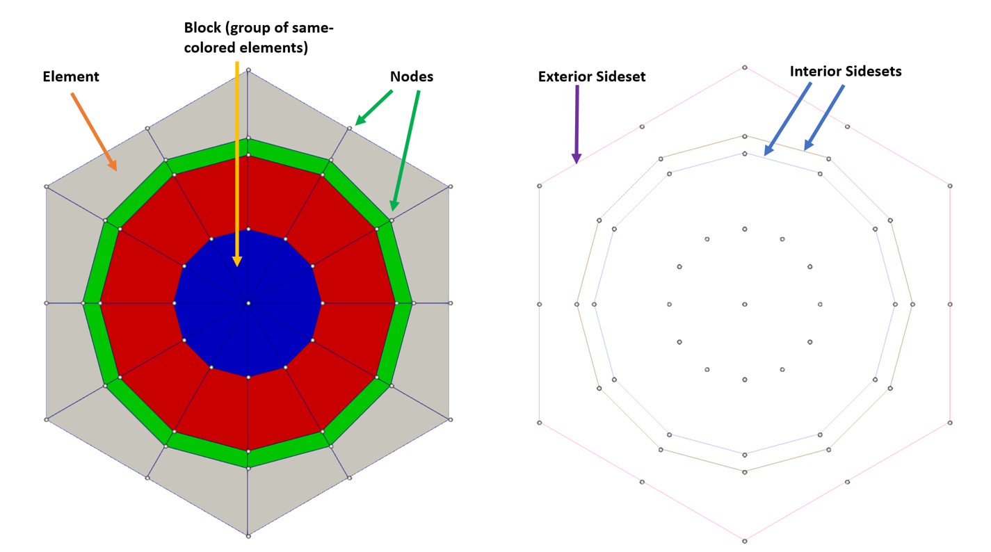
Finite Element (or simply Element)
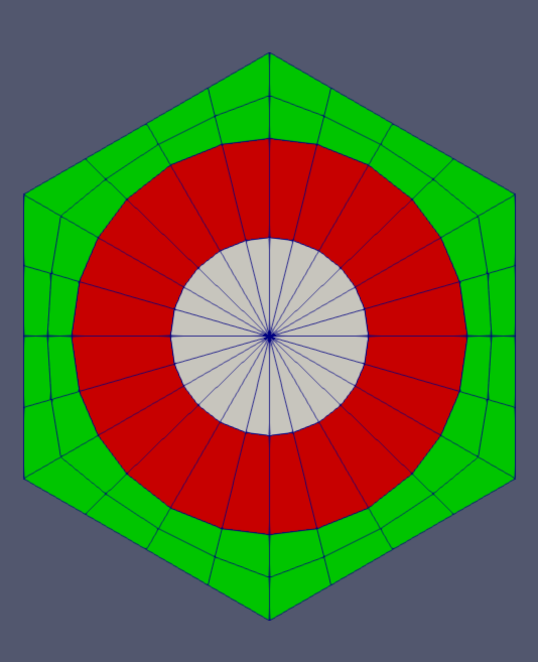
An ordered grouping of nodes that defines the boundaries of a piece of the spatial domain. A typical first order 2D element has 3 (triangle) or 4 (quadrilateral) nodes. Straight lines connect the nodes to form the element shape. In 3D, typical elements have 6 (triangular prism), 8 (hexahedron), 4 (tetrahedron) or 5 (pyramid) nodes. The full set of elements comprises the mesh which approximates the geometry. Basis functions from the FEM are defined on each element. Higher order elements may have additional nodes than those listed here, and may have curved geometries. A mesh can consist of different types of elements.
This mesh has 48 unique elements (12 triangular in the center, and 36 quadrilateral).
Block (or Subdomain)
A grouping of elements which must have similar type and order. A mesh may have few or many blocks.
This mesh has 4 unique blocks: 1 triangular element block (blue), and 3 quadrilateral element blocks (red, green, gray).
Node
A coordinate point in space, connected to one or more elements, which will be used along with other nodes to define element shape.
Nodes are highlighted as small circles in this mesh. Nodes specify the vertices of linear triangular and quadrilateral elements.
Nodeset
A grouping of nodes. Nodes can belong to more than one nodeset.
This mesh has 3 nodesets, one pertaining to each sideset. Nodes within each nodeset link together to form the sideset edges.
Sideset
A grouping of element edges or faces (in 2D & 3D respectively) categorized by their owning surfaces or volumes. These are associated with elements and this association is determined by a normal direction to the edge or face. Edges or faces may belong to more than one sideset.
This mesh has 3 unique sidesets (1 exterior sideset and 2 interior sidesets). No sideset was created between the blue and red blocks because these actually represent the same material (fuel) and therefore there is no material interface, information transfer, or boundary condition to apply here.
Frequently Used Reactor Geometries and Corresponding Mesh Generators
This section lists frequently used hexagonal-based geometries for reactor cores and their associated mesh generator objects. All the following are considered "base" mesh generators which expose all input options including control of block (subdomain) numbering. While sidesets can also be numbered, the outer boundary sideset is automatically assigned to sideset 10000.
A second set of mesh generators (Reactor Geometry Mesh Builder mesh generators) is available for regular hexagonal and Cartesian geometry and provides a reduced set of input options, removes any mention of block (subdomain) numbering, and instead allows the user to specify materials directly on the mesh. These are covered in another Chapter.
Pin Cell
The pin cell size may be provided as the apothem (center-to-flat distance which is the pin "half-pitch") or radius (center-to-vertex distance) depending on the setting in "polygon_size_style"
2D Cartesian or hex pin cell, including fuel, clad, coolant and (optional) ducted regions
Permits either quadrilateral or triangular elements in the pin center region (quad fuel and tri fuel regions must have different block IDs)
Fuel area preservation using the "preserve_volumes" parameter
Different azimuthal discretization possible per pin cell face
[Mesh<<<{"href": "../../../../syntax/Mesh/index.html"}>>>]
  [hex_1]
    type = PolygonConcentricCircleMeshGenerator<<<{"description": "This PolygonConcentricCircleMeshGenerator object is designed to mesh a polygon geometry with optional rings centered inside.", "href": "../../../../source/meshgenerators/PolygonConcentricCircleMeshGenerator.html"}>>>
    # General parameters
    num_sides<<<{"description": "Number of sides of the polygon."}>>> = 6
    num_sectors_per_side<<<{"description": "Number of azimuthal sectors per polygon side (rotating counterclockwise from top right face)."}>>> = '4 4 4 4 4 4'
    polygon_size<<<{"description": "Size of the polygon to be generated (given as either apothem or radius depending on polygon_size_style)."}>>> = 5.0
    # Ring regions parameters
    ring_radii<<<{"description": "Radii of major concentric circles (rings)."}>>> = 4.0
    ring_intervals<<<{"description": "Number of radial mesh intervals within each major concentric circle excluding their boundary layers."}>>> = 2
    ring_block_ids<<<{"description": "Optional customized block ids for each ring geometry block."}>>> = '10 15'
    ring_block_names<<<{"description": "Optional customized block names for each ring geometry block."}>>> = 'center_tri center'
    preserve_volumes<<<{"description": "Volume of concentric circles can be preserved using this function."}>>> = on
    # Background region parameters
    background_intervals<<<{"description": "Number of radial meshing intervals in background region (area between rings and ducts) excluding the background's boundary layers."}>>> = 2
    background_block_ids<<<{"description": "Optional customized block id for the background block."}>>> = 20
    background_block_names<<<{"description": "Optional customized block names for the background block."}>>> = background
    #    # Optional Duct regions parameters
    #    duct_sizes = '4.5 4.8'
    #    duct_sizes_style = apothem
    #    duct_block_ids = '22 24'
    #    duct_block_names = 'duct_in duct_out'
    #    duct_intervals = '1 2'
  []
[]
Assembly (Homogenized)
2D Hexagonal unit pin cell with coarse mesh discretization
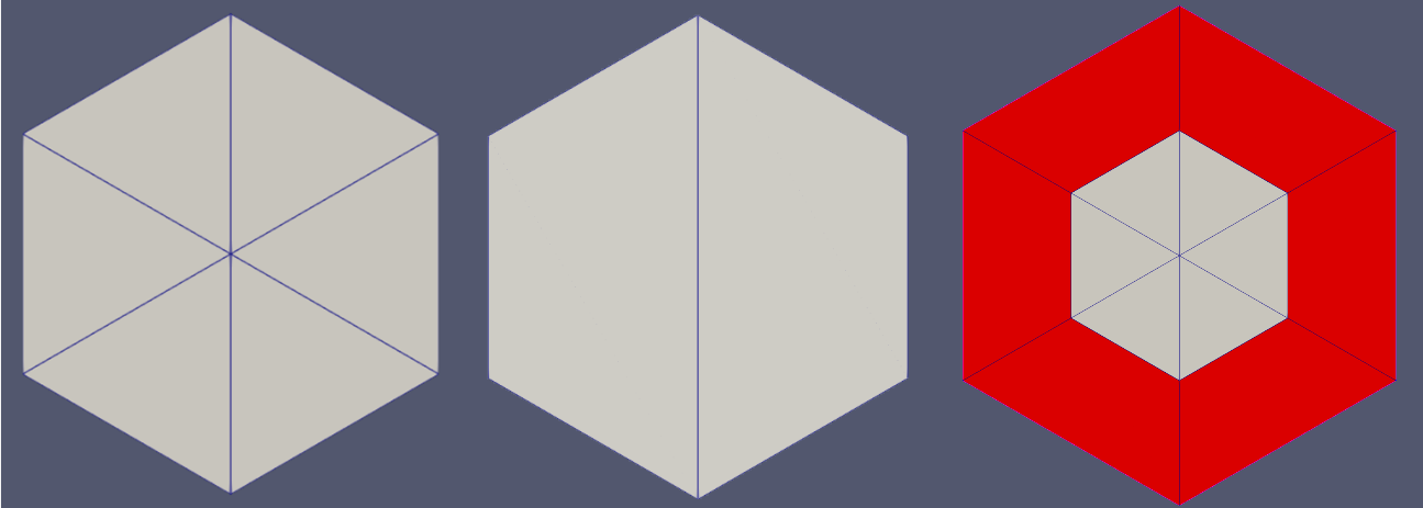
Three modes are available to discretize the hexagon:
TRI: 6 triangles (default)
QUAD: 2 quadrilateral elements
HYBRID: 6 triangles + 6 * number of layers of quadrilateral elements
[Mesh<<<{"href": "../../../../syntax/Mesh/index.html"}>>>]
  [hex_simple]
    type = SimpleHexagonGenerator<<<{"description": "This SimpleHexagonGenerator object is designed to generate a simple hexagonal mesh that only contains six simple azimuthal triangular elements, two quadrilateral elements, or six central azimuthal triangular elements plus a several layers of quadrilateral elements.", "href": "../../../../source/meshgenerators/SimpleHexagonGenerator.html"}>>>
    hexagon_size<<<{"description": "Size of the hexagon to be generated."}>>> = 16
    # Options: TRI, QUAD, HYBRID
    element_type<<<{"description": "Whether the simple hexagon mesh is made of TRI or QUAD elements."}>>> = TRI
    # Optional subdomain id/name
    block_id<<<{"description": "Optional customized block id; two ids are needed for HYBRID 'element_type'."}>>> = '100'
    block_name<<<{"description": "Optional customized block name; two names are needed for HYBRID 'element_type'."}>>> = 'hexagon'
  []
[]
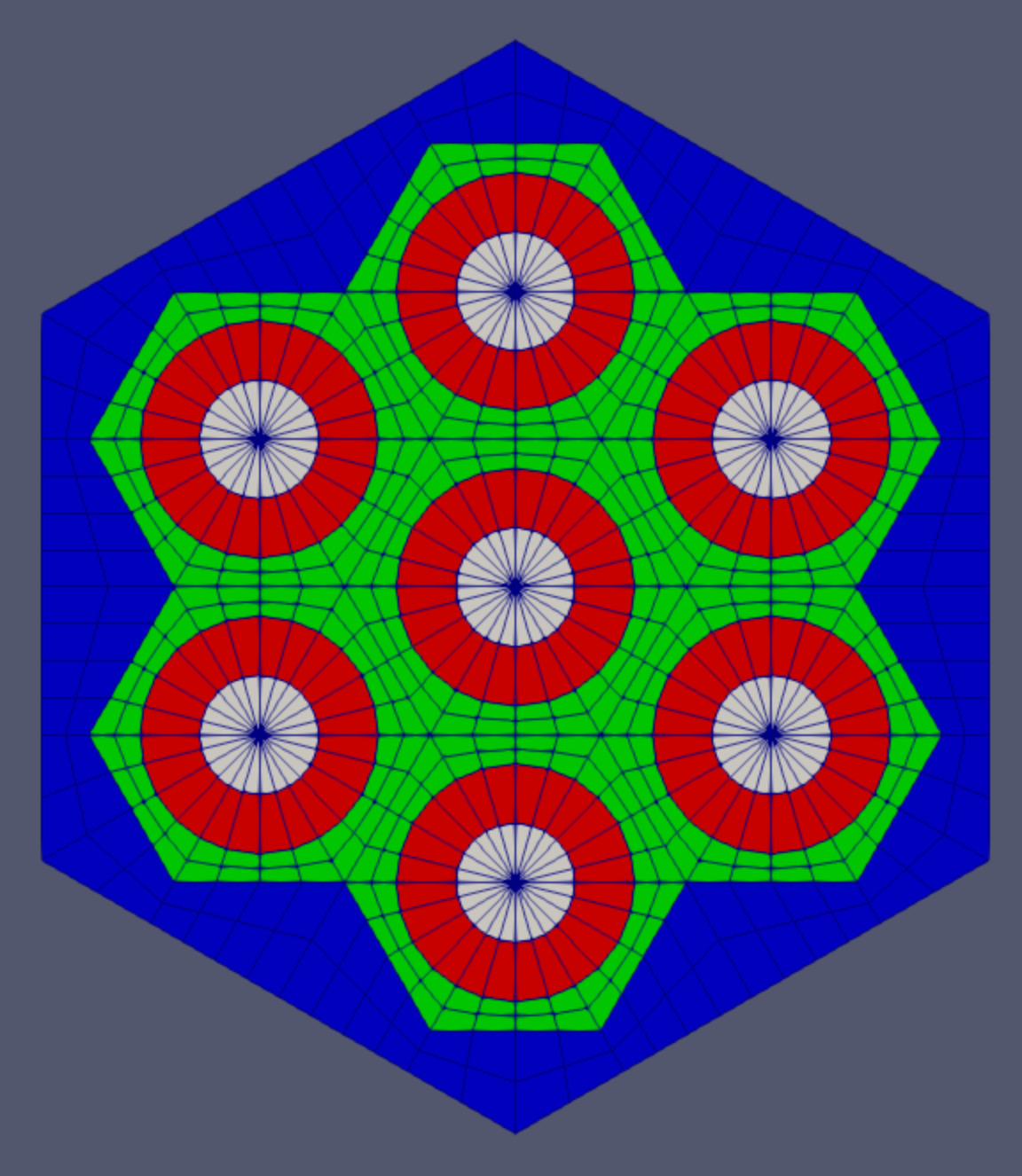
Assembly (with multiple heterogeneous pins)
(Cartesian sibling – PatternedCartesianMeshGenerator)
2D Regular assembly with uniform pin pitch
Optional background and duct regions
When generating an assembly mesh using PatternedHexMeshGenerator, be sure to set "generate_core_metadata" as
falseInput will be automatically rotated 90 degrees CCW unless specified with "rotate_angle"
[Mesh<<<{"href": "../../../../syntax/Mesh/index.html"}>>>]
  [pattern_assm]
    type = PatternedHexMeshGenerator<<<{"description": "This PatternedHexMeshGenerator source code assembles hexagonal meshes into a hexagonal grid and optionally forces the outer boundary to be hexagonal and/or adds a duct.", "href": "../../../../source/meshgenerators/PatternedHexMeshGenerator.html"}>>>
    inputs<<<{"description": "The input MeshGenerators."}>>> = 'hex_1'
    pattern<<<{"description": "A double-indexed hexagonal-shaped array starting with the upper-left corner."}>>> = '0 0;
              0 0 0;
               0 0'
    hexagon_size<<<{"description": "Size of the outmost hexagon boundary to be generated; this is required only when pattern type is 'hexagon'."}>>> = 16
    # Background region parameters
    background_intervals<<<{"description": "Radial intervals in the assembly peripheral region."}>>> = 2
    background_block_id<<<{"description": "Optional customized block id for the background block in 'assembly' mode; must be provided along with 'duct_block_ids' if 'duct_sizes' is provided."}>>> = 80
    background_block_name<<<{"description": "Optional customized block name for the background block in 'assembly' mode; must be provided along with 'duct_block_names' if 'duct_sizes' is provided."}>>> = hex_background
    #    # Optional Duct regions parameters
    #    duct_sizes = '15.0 15.5'
    #    duct_sizes_style = apothem
    #    duct_block_ids = '82 84'
    #    duct_block_names = 'assm_duct_in assm_duct_out'
    #    duct_intervals = '1 2'
    # Advanced option
    deform_non_circular_region<<<{"description": "Whether the non-circular region (outside the rings) can be deformed."}>>> = false
  []
[]
Assembly (control drum, duct-heterogeneous, or single pin)
(Cartesian sibling – CartesianConcentricCircleAdaptiveBoundaryMeshGenerator)
Hexagonal mesh with assembly metadata
Can optionally match other assembly meshes' external boundary to enable stitching to generate core meshes.
It can be used without specifying "sides_to_adapt" and "meshes_to_adapt_to" to generate PolygonConcentricCircleMeshGenerator -style hexagonal mesh with assembly mesh metadata
[Mesh<<<{"href": "../../../../syntax/Mesh/index.html"}>>>]
  [adaptive_assm]
    type = HexagonConcentricCircleAdaptiveBoundaryMeshGenerator<<<{"description": "This HexagonConcentricCircleAdaptiveBoundaryMeshGenerator object is designed to generate hexagonal meshes with adaptive boundary to facilitate stitching.", "href": "../../../../source/meshgenerators/HexagonConcentricCircleAdaptiveBoundaryMeshGenerator.html"}>>>
    num_sectors_per_side<<<{"description": "Number of azimuthal sectors per polygon side (rotating counterclockwise from top right face)."}>>> = '4 4 4 4 4 4'
    background_intervals<<<{"description": "Number of radial meshing intervals in background region (area between rings and ducts) excluding the background's boundary layers."}>>> = 2
    hexagon_size<<<{"description": "Size of the hexagon to be generated."}>>> = 16
    sides_to_adapt<<<{"description": "List of the hexagon reference side indices that correspond to the sides that need adaptive meshing. The meshes to adapt these sides to are provided in 'inputs'."}>>> = '1 2 3'
    meshes_to_adapt_to<<<{"description": "The name list of the input meshes to adapt to."}>>> = 'pattern_assm pattern_assm pattern_assm'
  []
[]
Core
(Cartesian sibling – PatternedCartesianMeshGenerator)
2D regular assembly pattern with uniform assembly pitch
Assembly meshes generated by PatternedHexMeshGenerator, HexagonConcentricCircleAdaptiveBoundaryMeshGenerator and SimpleHexagonGenerator can be used as inputs
Core mesh generation should include the parameter "generate_core_metadata" as
true.The pattern will be automatically rotated 90 degrees CCW unless specified with "rotate_angle"
[Mesh<<<{"href": "../../../../syntax/Mesh/index.html"}>>>]
  [pattern_core]
    type = PatternedHexMeshGenerator<<<{"description": "This PatternedHexMeshGenerator source code assembles hexagonal meshes into a hexagonal grid and optionally forces the outer boundary to be hexagonal and/or adds a duct.", "href": "../../../../source/meshgenerators/PatternedHexMeshGenerator.html"}>>>
    inputs<<<{"description": "The input MeshGenerators."}>>> = 'pattern_assm adaptive_assm'
    pattern_boundary<<<{"description": "The boundary shape of the patterned mesh."}>>> = none
    # Set as true to tell MOOSE that inputs have meshes made by PatternedHexMeshGenerator
    # Set as false if the inputs are made by SimpleHexagonGenerator
    generate_core_metadata<<<{"description": "A Boolean parameter that controls whether the core related metadata is generated for other MOOSE objects such as 'MultiControlDrumFunction' or not."}>>> = true
    pattern<<<{"description": "A double-indexed hexagonal-shaped array starting with the upper-left corner."}>>> = '0 0 0;
              0 0 0 0;
             0 0 0 0 1;
              0 0 0 0;
               0 0 0'
  []
[]
Core Periphery (PRMG)
PeripheralRingMeshGenerator (abbreviated as PRMG)
Adds circular peripheral region to a reactor core mesh
PeripheralRingMeshGenerator has a boundary layer capability
PeripheralRingMeshGenerator generates a structured peripheral mesh with QUAD4 elements
[Mesh<<<{"href": "../../../../syntax/Mesh/index.html"}>>>]
  [pr]
    type = PeripheralRingMeshGenerator<<<{"description": "This PeripheralRingMeshGenerator object adds a circular peripheral region to the input mesh.", "href": "../../../../source/meshgenerators/PeripheralRingMeshGenerator.html"}>>>
    input<<<{"description": "The input mesh to be modified."}>>> = pattern_core
    peripheral_layer_num<<<{"description": "The radial layers of the peripheral ring to be added."}>>> = 3
    peripheral_ring_radius<<<{"description": "Radius of the peripheral ring to be added."}>>> = 100.0
    input_mesh_external_boundary<<<{"description": "The external boundary of the input mesh."}>>> = 10000
    peripheral_ring_block_id<<<{"description": "The block id assigned to the created peripheral layer."}>>> = 300
    peripheral_ring_block_name<<<{"description": "The block name assigned to the created peripheral layer."}>>> = reactor_ring
  []
[]
Core Periphery (PTMG)
PeripheralTriangleMeshGenerator (abbreviated as PTMG)
Adds circular peripheral region to a reactor core mesh
PeripheralTriangleMeshGenerator generates an unstructured peripheral mesh with TRI3 elements
Automatic element area refinement is available
[Mesh<<<{"href": "../../../../syntax/Mesh/index.html"}>>>]
  [pt]
    type = PeripheralTriangleMeshGenerator<<<{"description": "This PeripheralTriangleMeshGenerator object is designed to generate a triangulated mesh between a generated outer circle boundary and a provided inner mesh.", "href": "../../../../source/meshgenerators/PeripheralTriangleMeshGenerator.html"}>>>
    input<<<{"description": "The input mesh to be modified."}>>> = pattern_core
    peripheral_ring_radius<<<{"description": "Radius of the peripheral ring to be added."}>>> = 100.0
    peripheral_ring_num_segments<<<{"description": "Number of segments of the peripheral ring."}>>> = 100
    desired_area<<<{"description": "Desired (maximum) triangle area, or 0 to skip uniform refinement"}>>> = 20
  []
[]
Frequently Used Operations and Corresponding MeshGenerators
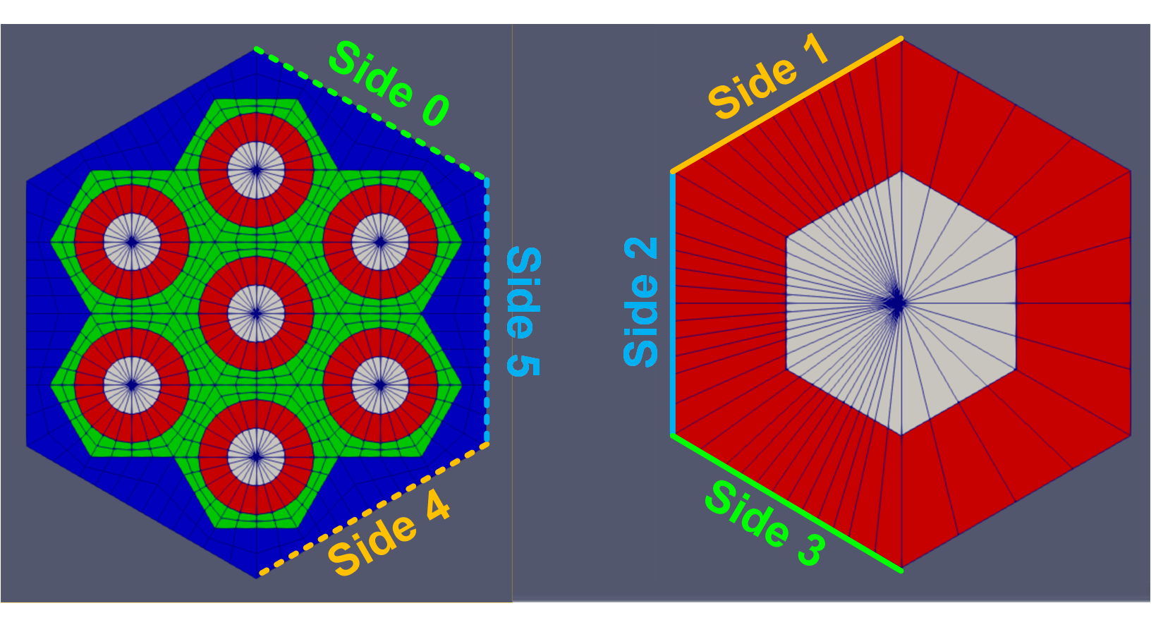
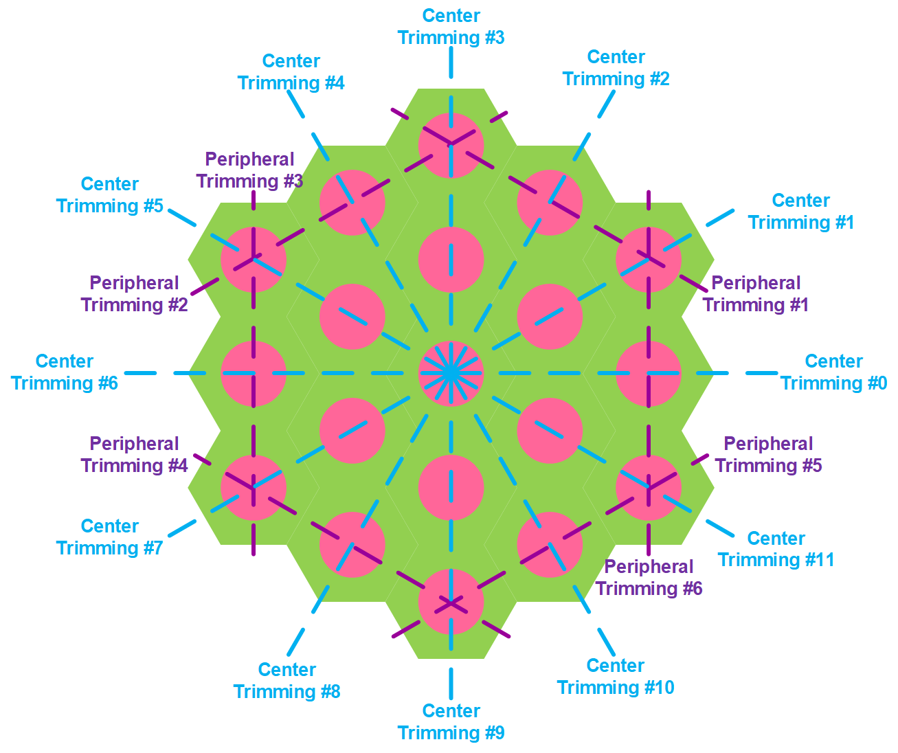
Mesh Trimming Along Lines of Symmetry
(Cartesian sibling – CartesianMeshTrimmer)
Two types of trimming can be performed by HexagonMeshTrimmer: Peripheral Trimming and Through-the-Center Trimming.
Peripheral trimming can be performed on six possible lines, each of which is parallel to a side of the hexagon and crosses the center of the pins laid out in that direction
Peripheral trimming can only be used for assembly meshes
Through-the-center trimming can be used for both assembly and core meshes
Mesh Trimming Examples
[Mesh<<<{"href": "../../../../syntax/Mesh/index.html"}>>>]
  [pattern_assm_peri_trim]
    type = HexagonMeshTrimmer<<<{"description": "This HexagonMeshTrimmer object performs peripheral and/or across-center (0, 0, 0) trimming for assembly or core 2D meshes generated by PatternedHexMG.", "href": "../../../../source/meshgenerators/HexagonMeshTrimmer.html"}>>>
    input<<<{"description": "The input mesh that needs to be trimmed."}>>> = pattern_assm
    trim_peripheral_region<<<{"description": "Whether the peripheral region on each of the six sides will be trimmed in an assembly mesh. See documentation for numbering convention."}>>> = '1 1 1 1 1 1'
    peripheral_trimming_section_boundary<<<{"description": "Boundary formed by peripheral trimming."}>>> = peripheral_section
  []
[]
[Mesh<<<{"href": "../../../../syntax/Mesh/index.html"}>>>]
[core_trim]
type = HexagonMeshTrimmer<<<{"description": "This HexagonMeshTrimmer object performs peripheral and/or across-center (0, 0, 0) trimming for assembly or core 2D meshes generated by PatternedHexMG.", "href": "../../../../source/meshgenerators/HexagonMeshTrimmer.html"}>>>
input<<<{"description": "The input mesh that needs to be trimmed."}>>> = pr
center_trim_starting_index<<<{"description": "Index of the starting center trimming position."}>>> = 0
center_trim_ending_index<<<{"description": "Index of the ending center trimming position."}>>> = 2
center_trimming_section_boundary<<<{"description": "Boundary formed by center trimming (external_boundary will be assigned if this parameter is not provided)."}>>> = symmetric
[]
[]Assembly Periphery Modification
(Cartesian sibling – PatternedCartesianPeripheralModifier)
Modify the peripheral region of an assembly mesh to enforce a given number of nodes uniformly distributed on the external boundary to facilitate the stitching of different assembly meshes.
The input mesh must be an assembly with a hexagonal boundary (coolant and/or duct region(s) present).
[Mesh<<<{"href": "../../../../syntax/Mesh/index.html"}>>>]
  [pattern_assm_peri_mod]
    type = PatternedHexPeripheralModifier<<<{"description": "PatternedPolygonPeripheralModifierBase is the base class for PatternedCartPeripheralModifier and PatternedHexPeripheralModifier.", "href": "../../../../source/meshgenerators/PatternedHexPeripheralModifier.html"}>>>
    input<<<{"description": "The input mesh to be modified. Note that this generator only works with PatternedHex/CartesianMeshGenerator and its derived classes such as HexIDPatternedMeshGenerator."}>>> = pattern_assm
    input_mesh_external_boundary<<<{"description": "The external boundary of the input mesh."}>>> = 10000
    new_num_sector<<<{"description": "Number of sectors of each side for the new mesh."}>>> = 10
    num_layers<<<{"description": "Layers of elements for transition."}>>> = 2
  []
[]
Extrusion to 3D
Extrudes a 1D mesh into 2D, or 2D into 3D
Variable height / # of layers in each height
Variable growth factors of axial element sizes within each elevation
Remap subdomain IDs, boundary IDs and element EEIDs in each elevation and boundaries between neighboring elevations
Extrusion may be performed along any direction specified by an vector. Most common is (+-direction).
[Mesh<<<{"href": "../../../../syntax/Mesh/index.html"}>>>]
  [core_ext]
    type = AdvancedExtruderGenerator<<<{"description": "Extrudes a 1D mesh into 2D, or a 2D mesh into 3D, and supports a variable height for each elevation, variable number of layers within each elevation, variable growth factors of axial element sizes within each elevation and remap subdomain_ids, boundary_ids and element extra integers within each elevation as well as interface boundaries between neighboring elevation layers, as well as following a 1D curve and modifying the radial (normal to the extrusion axis) extent of the geometry.", "href": "../../../../source/meshgenerators/AdvancedExtruderGenerator.html"}>>>
    input<<<{"description": "The mesh to extrude"}>>> = core_trim
    heights<<<{"description": "The height of each elevation"}>>> = '30 60 30'
    num_layers<<<{"description": "The number of layers for each elevation - must be num_elevations in length!"}>>> = '2 3 2'
    direction<<<{"description": "A vector that points in the direction to extrude (note, this will be normalized internally - so don't worry about it here)"}>>> = '0 0 1'
    # Optional subdomain swap
    subdomain_swaps<<<{"description": "For each row, every two entries are interpreted as a pair of 'from' and 'to' to remap the subdomains for that elevation"}>>> = '10 100 15 150 20 150 80 150 300 150;
                        ;
                       10 200 15 250 20 250 80 250 300 250'
  []
[]
Reporting IDs: A Powerful Feature for Assisting with Physics Input and Output Processing
Why do we need Reporting IDs?
In reactor simulations, we want to bookkeep the individual elements belonging to each geometric component
Assign material properties to the mesh in different regions
Extract integral quantities from the solution in different regions
Using numerous block IDs just to differentiate regions is not practical or sufficient
Using excessive blocks can cause performance degradation in MOOSE
Multiple hierarchical levels in geometries (e.g., pin, assembly) cannot be represented with blocks
Reporting IDs were introduced as a practical solution to this bookkeeping issue
What are Reporting IDs?
Reporting IDs are extra integer ID tags assigned on each element of the mesh
A reporting ID consists of a name (e.g. pin_id, assembly_id) and an assigned value (e.g. 1, 2, 3...)
A reporting ID designates association with a specific reactor component or zone, such as pin ID or assembly ID
An element may have multiple reporting IDs to track different information (e.g., pin number, assembly number, plane number).
How do we get reporting IDs on mesh elements?
The automatic assignment of reporting IDs to elements in a mesh is provided through several mesh generators that "understand" the concept of pins, assemblies, planes, etc.
There is no need to provide physical locations or coordinates of elements in order to assign IDs
How can we use reporting IDs?
Reporting IDs can be used to assign material properties
Reporting IDs can be used to create additional unique zones (e.g. depletion zones)
Reporting IDs can be leveraged to post-process solution data into tables by using the ExtraIDIntegralVectorPostprocessor. This postprocessor integrates the solution based on reporting IDs. Component-wise values such as pin-by-pin power distribution can be easily yielded by specifying integration over pin and assembly reporting IDs to this postprocessor.
Reporting IDs can be generated from the block ID (subdomain ID) mapping using SubdomainExtraElementIDGenerator or copied over from an existing reporting ID name using ExtraElementIDCopyGenerator. Otherwise the mesh generators describes in the next slides explain how they can be defined from scratch for typical mesh generation workflows.
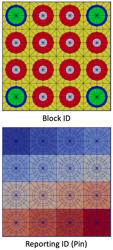
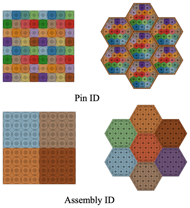
Applying Reporting IDs for Cartesian and Hexagonal Lattices
PatternedCartesianMeshGenerator (Cartesian)
PatternedHexMeshGenerator (Hexagonal)
Assign reporting IDs for input geometric components (pins or assemblies) during lattice mesh generations.
Supports the following numbering schemes (set with "assign_type"):
cell(default): Assign unique IDs for each component in the lattice in sequential order (begins at 0 in the top left corner of the pattern).pattern: assign a different ID for each unique input componentmanual: use a manual numbering scheme provided by user
When assembly duct regions are present, these regions are numbered sequentially starting from the inner-most region to the outer-most region.
Pin and Assembly IDs are applied during creations of assemblies and core, respectively.
FlexiblePatternGenerator also supports creation of reporting IDs for each unique pin structure (See "Advanced Meshing Tools" section)
Cell Pattern Example
[Mesh<<<{"href": "../../../../syntax/Mesh/index.html"}>>>]
[pin1]
type = PolygonConcentricCircleMeshGenerator<<<{"description": "This PolygonConcentricCircleMeshGenerator object is designed to mesh a polygon geometry with optional rings centered inside.", "href": "../../../../source/meshgenerators/PolygonConcentricCircleMeshGenerator.html"}>>>
num_sides<<<{"description": "Number of sides of the polygon."}>>> = 4
num_sectors_per_side<<<{"description": "Number of azimuthal sectors per polygon side (rotating counterclockwise from top right face)."}>>> = '2 2 2 2'
background_intervals<<<{"description": "Number of radial meshing intervals in background region (area between rings and ducts) excluding the background's boundary layers."}>>> = 1
ring_radii<<<{"description": "Radii of major concentric circles (rings)."}>>> = '0.4 0.5'
ring_intervals<<<{"description": "Number of radial mesh intervals within each major concentric circle excluding their boundary layers."}>>> = '1 1'
polygon_size<<<{"description": "Size of the polygon to be generated (given as either apothem or radius depending on polygon_size_style)."}>>> = 0.63
flat_side_up<<<{"description": "Whether to rotate the generated polygon mesh to ensure that one flat side faces up."}>>> = true
[]
[pin2]
type = PolygonConcentricCircleMeshGenerator<<<{"description": "This PolygonConcentricCircleMeshGenerator object is designed to mesh a polygon geometry with optional rings centered inside.", "href": "../../../../source/meshgenerators/PolygonConcentricCircleMeshGenerator.html"}>>>
num_sides<<<{"description": "Number of sides of the polygon."}>>> = 4
num_sectors_per_side<<<{"description": "Number of azimuthal sectors per polygon side (rotating counterclockwise from top right face)."}>>> = '2 2 2 2'
background_intervals<<<{"description": "Number of radial meshing intervals in background region (area between rings and ducts) excluding the background's boundary layers."}>>> = 1
ring_radii<<<{"description": "Radii of major concentric circles (rings)."}>>> = '0.4 0.5'
ring_intervals<<<{"description": "Number of radial mesh intervals within each major concentric circle excluding their boundary layers."}>>> = '1 1'
polygon_size<<<{"description": "Size of the polygon to be generated (given as either apothem or radius depending on polygon_size_style)."}>>> = 0.63
flat_side_up<<<{"description": "Whether to rotate the generated polygon mesh to ensure that one flat side faces up."}>>> = true
[]
[assembly1]
type = PatternedCartesianMeshGenerator<<<{"description": "This PatternedCartesianMeshGenerator source code assembles square meshes into a square grid and optionally forces the outer boundary to be square and/or adds a duct.", "href": "../../../../source/meshgenerators/PatternedCartesianMeshGenerator.html"}>>>
inputs<<<{"description": "The names of the meshes forming the pattern."}>>> = 'pin1 pin2'
pattern<<<{"description": "A two-dimensional cartesian (square-shaped) array starting with the upper-left corner.It is composed of indexes into the inputs vector"}>>> = ' 1 0 1 0;
0 1 0 1;
1 0 1 0;
0 1 0 1'
assign_type<<<{"description": "List of integer ID assignment types"}>>> = 'cell'
id_name<<<{"description": "List of extra integer ID set names"}>>> = 'pin_id'
pattern_boundary<<<{"description": "The boundary shape of the patterned mesh."}>>> = 'none'
generate_core_metadata<<<{"description": "A Boolean parameter that controls whether the core related metadata is generated for other MOOSE objects such as 'MultiControlDrumFunction' or not."}>>> = false
[]
[assembly2]
type = PatternedCartesianMeshGenerator<<<{"description": "This PatternedCartesianMeshGenerator source code assembles square meshes into a square grid and optionally forces the outer boundary to be square and/or adds a duct.", "href": "../../../../source/meshgenerators/PatternedCartesianMeshGenerator.html"}>>>
inputs<<<{"description": "The names of the meshes forming the pattern."}>>> = 'pin1 pin2'
pattern<<<{"description": "A two-dimensional cartesian (square-shaped) array starting with the upper-left corner.It is composed of indexes into the inputs vector"}>>> = ' 0 1 1 0;
1 0 0 1;
1 0 0 1;
0 1 1 0'
assign_type<<<{"description": "List of integer ID assignment types"}>>> = 'cell'
id_name<<<{"description": "List of extra integer ID set names"}>>> = 'pin_id'
pattern_boundary<<<{"description": "The boundary shape of the patterned mesh."}>>> = 'none'
generate_core_metadata<<<{"description": "A Boolean parameter that controls whether the core related metadata is generated for other MOOSE objects such as 'MultiControlDrumFunction' or not."}>>> = false
[]
[core]
type = PatternedCartesianMeshGenerator<<<{"description": "This PatternedCartesianMeshGenerator source code assembles square meshes into a square grid and optionally forces the outer boundary to be square and/or adds a duct.", "href": "../../../../source/meshgenerators/PatternedCartesianMeshGenerator.html"}>>>
inputs<<<{"description": "The names of the meshes forming the pattern."}>>> = 'assembly1 assembly2'
pattern<<<{"description": "A two-dimensional cartesian (square-shaped) array starting with the upper-left corner.It is composed of indexes into the inputs vector"}>>> = '0 1;
1 0'
assign_type<<<{"description": "List of integer ID assignment types"}>>> = 'cell'
id_name<<<{"description": "List of extra integer ID set names"}>>> = 'assembly_id'
pattern_boundary<<<{"description": "The boundary shape of the patterned mesh."}>>> = 'none'
generate_core_metadata<<<{"description": "A Boolean parameter that controls whether the core related metadata is generated for other MOOSE objects such as 'MultiControlDrumFunction' or not."}>>> = true
[]
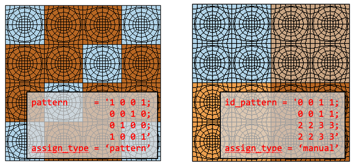
[]Alternative Pattern Example
Supports other numbering schemes:
"assign_type" =
pattern: Assign IDs identical to the already-provided "pattern" array"assign_type" =
manual: Assign IDs based on a user-defined mapping in the optional "id_pattern" array, which may differ from the required "pattern" array
[Mesh<<<{"href": "../../../../syntax/Mesh/index.html"}>>>]
  [pin1]
    type = PolygonConcentricCircleMeshGenerator<<<{"description": "This PolygonConcentricCircleMeshGenerator object is designed to mesh a polygon geometry with optional rings centered inside.", "href": "../../../../source/meshgenerators/PolygonConcentricCircleMeshGenerator.html"}>>>
    num_sides<<<{"description": "Number of sides of the polygon."}>>> = 4
    num_sectors_per_side<<<{"description": "Number of azimuthal sectors per polygon side (rotating counterclockwise from top right face)."}>>> = '2 2 2 2'
    background_intervals<<<{"description": "Number of radial meshing intervals in background region (area between rings and ducts) excluding the background's boundary layers."}>>> = 1
    ring_radii<<<{"description": "Radii of major concentric circles (rings)."}>>> = '0.4 0.5'
    ring_intervals<<<{"description": "Number of radial mesh intervals within each major concentric circle excluding their boundary layers."}>>> = '1 1'
    polygon_size<<<{"description": "Size of the polygon to be generated (given as either apothem or radius depending on polygon_size_style)."}>>> = 0.63
    flat_side_up<<<{"description": "Whether to rotate the generated polygon mesh to ensure that one flat side faces up."}>>> = true
  []

  [pin2]
    type = PolygonConcentricCircleMeshGenerator<<<{"description": "This PolygonConcentricCircleMeshGenerator object is designed to mesh a polygon geometry with optional rings centered inside.", "href": "../../../../source/meshgenerators/PolygonConcentricCircleMeshGenerator.html"}>>>
    num_sides<<<{"description": "Number of sides of the polygon."}>>> = 4
    num_sectors_per_side<<<{"description": "Number of azimuthal sectors per polygon side (rotating counterclockwise from top right face)."}>>> = '2 2 2 2'
    background_intervals<<<{"description": "Number of radial meshing intervals in background region (area between rings and ducts) excluding the background's boundary layers."}>>> = 1
    ring_radii<<<{"description": "Radii of major concentric circles (rings)."}>>> = '0.4 0.5'
    ring_intervals<<<{"description": "Number of radial mesh intervals within each major concentric circle excluding their boundary layers."}>>> = '1 1'
    polygon_size<<<{"description": "Size of the polygon to be generated (given as either apothem or radius depending on polygon_size_style)."}>>> = 0.63
    flat_side_up<<<{"description": "Whether to rotate the generated polygon mesh to ensure that one flat side faces up."}>>> = true
  []

  [assembly1]
    type = PatternedCartesianMeshGenerator<<<{"description": "This PatternedCartesianMeshGenerator source code assembles square meshes into a square grid and optionally forces the outer boundary to be square and/or adds a duct.", "href": "../../../../source/meshgenerators/PatternedCartesianMeshGenerator.html"}>>>
    inputs<<<{"description": "The names of the meshes forming the pattern."}>>> = 'pin1 pin2'
    pattern<<<{"description": "A two-dimensional cartesian (square-shaped) array starting with the upper-left corner.It is composed of indexes into the inputs vector"}>>> = ' 1  0  0  1;
                0  0  1  0;
                0  1  0  0;
                1  0  0  1'
    assign_type<<<{"description": "List of integer ID assignment types"}>>> = 'pattern'
    id_name<<<{"description": "List of extra integer ID set names"}>>> = 'pin_id'
    pattern_boundary<<<{"description": "The boundary shape of the patterned mesh."}>>> = 'none'
    generate_core_metadata<<<{"description": "A Boolean parameter that controls whether the core related metadata is generated for other MOOSE objects such as 'MultiControlDrumFunction' or not."}>>> = false
  []

  [assembly2]
    type = PatternedCartesianMeshGenerator<<<{"description": "This PatternedCartesianMeshGenerator source code assembles square meshes into a square grid and optionally forces the outer boundary to be square and/or adds a duct.", "href": "../../../../source/meshgenerators/PatternedCartesianMeshGenerator.html"}>>>
    inputs<<<{"description": "The names of the meshes forming the pattern."}>>> = 'pin1 pin2'
    pattern<<<{"description": "A two-dimensional cartesian (square-shaped) array starting with the upper-left corner.It is composed of indexes into the inputs vector"}>>> = ' 0  1  1  0;
                1  0  0  1;
                1  0  0  1;
                0  1  1  0'
    id_pattern<<<{"description": "User-defined element IDs. A double-indexed array starting with the upper-left corner. When providing multiple patterns, each pattern should be separated using '|'"}>>> = ' 0  0  1  1;
                   0  0  1  1;
                   2  2  3  3;
                   2  2  3  3'
    assign_type<<<{"description": "List of integer ID assignment types"}>>> = 'manual'
    id_name<<<{"description": "List of extra integer ID set names"}>>> = 'pin_id'
    pattern_boundary<<<{"description": "The boundary shape of the patterned mesh."}>>> = 'none'
    generate_core_metadata<<<{"description": "A Boolean parameter that controls whether the core related metadata is generated for other MOOSE objects such as 'MultiControlDrumFunction' or not."}>>> = false
  []

  [core]
    type = PatternedCartesianMeshGenerator<<<{"description": "This PatternedCartesianMeshGenerator source code assembles square meshes into a square grid and optionally forces the outer boundary to be square and/or adds a duct.", "href": "../../../../source/meshgenerators/PatternedCartesianMeshGenerator.html"}>>>
    inputs<<<{"description": "The names of the meshes forming the pattern."}>>> = 'assembly1 assembly2'
    pattern<<<{"description": "A two-dimensional cartesian (square-shaped) array starting with the upper-left corner.It is composed of indexes into the inputs vector"}>>> = '0  1;
               1  0'
    assign_type<<<{"description": "List of integer ID assignment types"}>>> = 'cell'
    id_name<<<{"description": "List of extra integer ID set names"}>>> = 'assembly_id'
    pattern_boundary<<<{"description": "The boundary shape of the patterned mesh."}>>> = 'none'
    generate_core_metadata<<<{"description": "A Boolean parameter that controls whether the core related metadata is generated for other MOOSE objects such as 'MultiControlDrumFunction' or not."}>>> = true
  []
[]
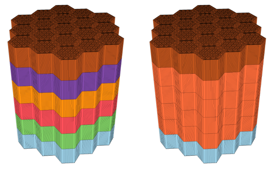
Applying Reporting IDs for Axial Plane
Apply reporting IDs between axial planes in an already extruded mesh
Only applicable for extruded geometries where the concept of axial layers (in , , or directions) is valid
The input mesh to this mesh generator should be 3D (this mesh generator does not perform the extrusion itself)
Unique IDs can be assigned between axial planes (coarse approach) or also to each unique sublayer defined by axial subintervals between the planes (fine approach)
[Mesh<<<{"href": "../../../../syntax/Mesh/index.html"}>>>]
[CORE_3D]
type = PlaneIDMeshGenerator<<<{"description": "Adds an extra element integer that identifies planes in a mesh.", "href": "../../../../source/meshgenerators/PlaneIDMeshGenerator.html"}>>>
input<<<{"description": "The mesh we want to modify"}>>> = 'CORE_3D_BASE'
plane_coordinates<<<{"description": "Coordinates of planes along the axis. The origin are at x/y/z=0 depending on the axis"}>>> = '0. 10. 50. 60.'
num_ids_per_plane<<<{"description": "Number of unique ids per plane"}>>> = '1 4 1'
id_name<<<{"description": "Name of extra integer ID set"}>>> = 'plane_id'
[]
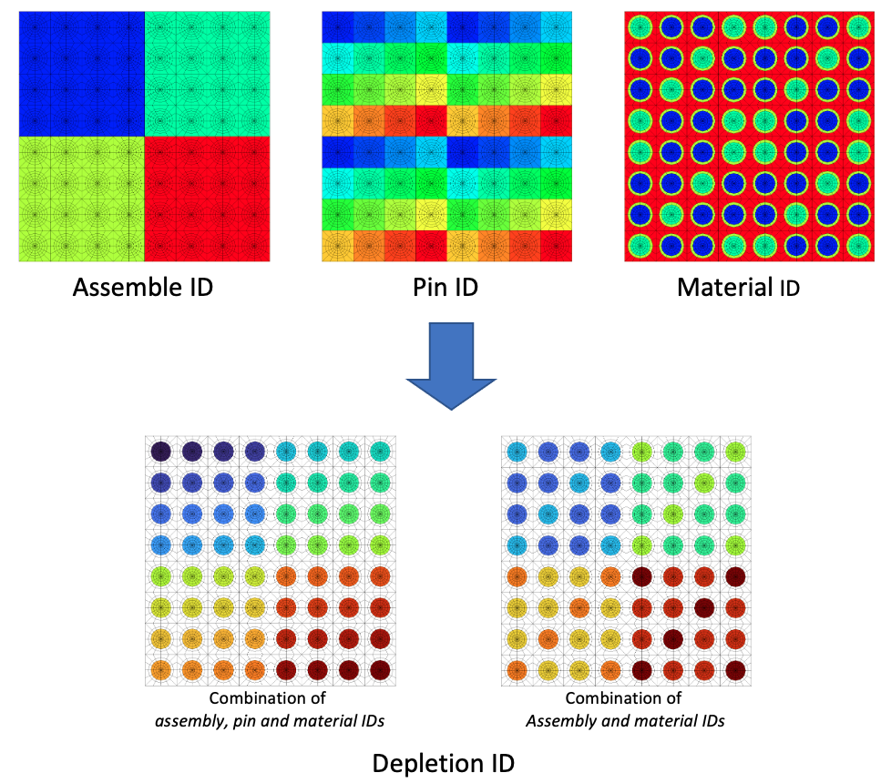
[]Applying Depletion IDs
Automatically assign depletion zones based on existing unique combination of reporting IDs and material ID
Easily control the fidelity of depletion zones based on the other reporting IDs already in the mesh (including block and material IDs)
For a pin-level depletion case, the depletion IDs for the entire domain can be specified by finding unique combinations of assembly, pin, and material IDs
By additionally including ring and sector IDs accessible through PolygonConcentricCircleMeshGenerator, depletion zones can be defined within the pin itself
[Mesh<<<{"href": "../../../../syntax/Mesh/index.html"}>>>]
  [depletion_id]
    type = DepletionIDGenerator<<<{"description": "This DepletionIDGenerator source code is to assign an extra element integer for elements on a mesh based on material and other extra element IDs that is typically used for depletion.", "href": "../../../../source/meshgenerators/DepletionIDGenerator.html"}>>>
    input<<<{"description": "Name of an existing mesh generator to which we assign element IDs"}>>> = 'core_mat_id'
    id_name<<<{"description": "Extra integer id names"}>>> = 'assembly_id pin_id'
    material_id_name<<<{"description": "Material id name"}>>> = 'material_id'
    exclude_id_name<<<{"description": "Extra ID names that need to be excluded in the depletion ID generation"}>>> = 'material_id'
    exclude_id_value<<<{"description": "Extra ID values corresponding to names defined in `exclude_id_name`"}>>> = '3 4'
  []
[]
Querying Output Data using Reporting IDs
Integrates solution variables over zones identified by combinations of reporting IDs
ExtraIDIntegralVectorPostprocessor exports the post-processed results in CSV file format
ExtraIDIntegralReporter, based on the MOOSE reporting system, can output in JSON file format

[VectorPostprocessors<<<{"href": "../../../../syntax/VectorPostprocessors/index.html"}>>>]
[integral]
type = ExtraIDIntegralVectorPostprocessor<<<{"description": "Integrates or averages variables based on extra element IDs", "href": "../../../../source/vectorpostprocessors/ExtraIDIntegralVectorPostprocessor.html"}>>>
variable<<<{"description": "The names of the variables that this VectorPostprocessor operates on"}>>> = 'variable_1 variable_2'
id_name<<<{"description": "List of extra element ID names by which to separate integral(s)."}>>> = 'assembly_id pin_id'
[]
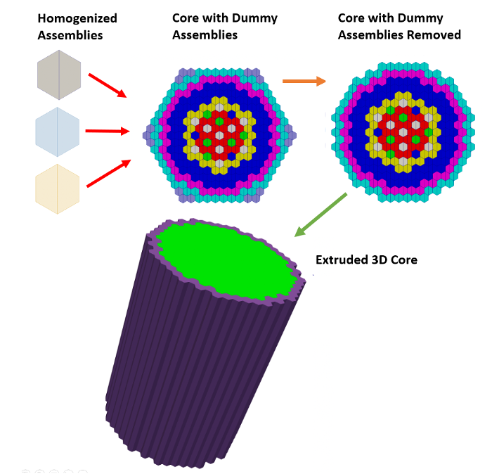
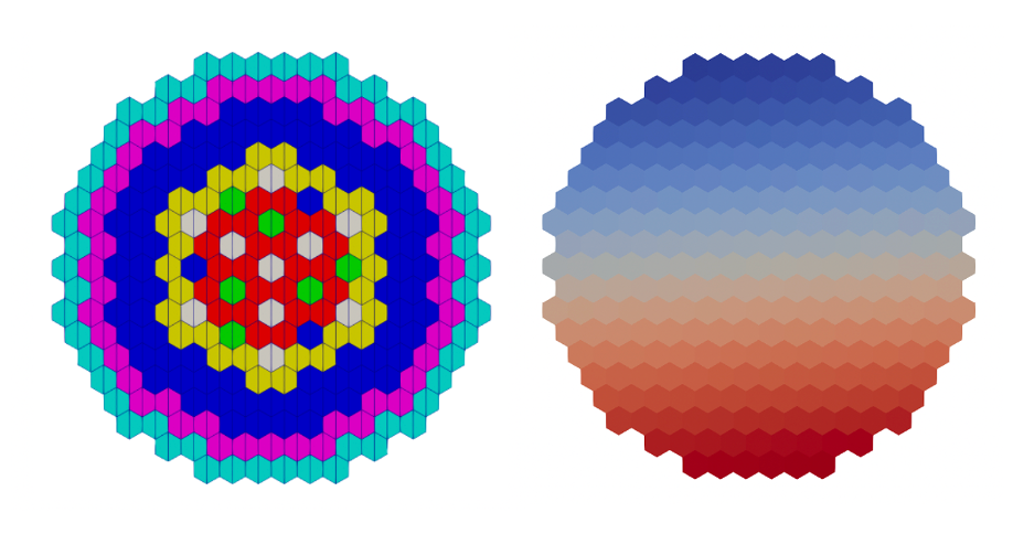
[]Example: Homogenous Assembly Fast Reactor Core (ABTR)
Homogenous Assembly Fast Reactor Core (ABTR)
We now build a sodium-cooled fast reactor core mesh for the Advanced Burner Test Reactor (ABTR) (Shemon et al. (2015)) using the following key steps:
Create homogenized hexagonal assemblies
Create dummy assemblies needed for core patterning
Combine assemblies into a full core
Delete dummy assemblies
Extrude 2D mesh to 3D
Assign plane-level reporting IDs
Rename outer boundary sidesets for later use in Griffin (optional)
Hands-on package MOOSE input file: tutorials/tutorial04_meshing/doc/listings/reactor_examples/abtr/abtr.i
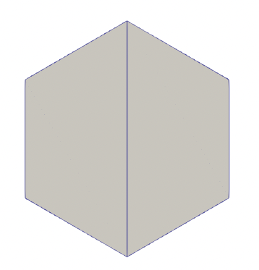
Define Homogeneous Hexagonal Assemblies
Hexagonal assembly
Size of 7.3425 (apothem style, center to wall distance, or half-pitch).
QUAD elements
Assign unique block ID to each assembly type
Each assembly type requires its own definition so that different materials can later be assigned to different assemblies (using block id as a differentiating factor)
Alternatively, using "element_type" =
TRIdiscretizes hexagonal assembly into 6 triangles
[Mesh<<<{"href": "../../../../syntax/Mesh/index.html"}>>>]
  [control]
    type = SimpleHexagonGenerator<<<{"description": "This SimpleHexagonGenerator object is designed to generate a simple hexagonal mesh that only contains six simple azimuthal triangular elements, two quadrilateral elements, or six central azimuthal triangular elements plus a several layers of quadrilateral elements.", "href": "../../../../source/meshgenerators/SimpleHexagonGenerator.html"}>>>
    hexagon_size<<<{"description": "Size of the hexagon to be generated."}>>> = 7.3425 # Half of the assembly pitch, which is 14.685
    hexagon_size_style<<<{"description": "Style in which the hexagon size is given (default: apothem i.e. half-pitch). Option: apothem radius"}>>> = 'apothem' # default
    element_type<<<{"description": "Whether the simple hexagon mesh is made of TRI or QUAD elements."}>>> = QUAD
    block_id<<<{"description": "Optional customized block id; two ids are needed for HYBRID 'element_type'."}>>> = '0'
  []
[]
Define Dummy Assemblies
Hexagonal assembly
7.3425 cm half-pitch
QUAD elements
Use a specific ID or name for the dummy in order to delete later in mesh generation process
[Mesh<<<{"href": "../../../../syntax/Mesh/index.html"}>>>]
  [dummy]
    type = SimpleHexagonGenerator<<<{"description": "This SimpleHexagonGenerator object is designed to generate a simple hexagonal mesh that only contains six simple azimuthal triangular elements, two quadrilateral elements, or six central azimuthal triangular elements plus a several layers of quadrilateral elements.", "href": "../../../../source/meshgenerators/SimpleHexagonGenerator.html"}>>>
    hexagon_size<<<{"description": "Size of the hexagon to be generated."}>>> = 7.3425
    hexagon_size_style<<<{"description": "Style in which the hexagon size is given (default: apothem i.e. half-pitch). Option: apothem radius"}>>> = 'apothem'
    element_type<<<{"description": "Whether the simple hexagon mesh is made of TRI or QUAD elements."}>>> = QUAD
    block_id<<<{"description": "Optional customized block id; two ids are needed for HYBRID 'element_type'."}>>> = '997'
  []
[]
Assemble Core Lattice
Uses all generated real assemblies and dummy assembly as input
The parameters "id_name", "assign_type", and "exclude_id" define how the
assembly_idreporting ID will be generated. We exclude the dummy assemblies from being assigned IDs.
[Mesh<<<{"href": "../../../../syntax/Mesh/index.html"}>>>]
  [core]
    type = PatternedHexMeshGenerator<<<{"description": "This PatternedHexMeshGenerator source code assembles hexagonal meshes into a hexagonal grid and optionally forces the outer boundary to be hexagonal and/or adds a duct.", "href": "../../../../source/meshgenerators/PatternedHexMeshGenerator.html"}>>>
    inputs<<<{"description": "The input MeshGenerators."}>>> = 'control inner_core test_fuel inner_reflector
              outer_core outer_reflector shield dummy'
    pattern_boundary<<<{"description": "The boundary shape of the patterned mesh."}>>> = none # do not add background coolant or a duct around this pattern
    rotate_angle<<<{"description": "Rotate the entire patterned mesh by a certain degrees that is defined here."}>>> = 0 # do not rotate (default is 90 degrees, i.e. vertex up)
    external_boundary_name<<<{"description": "Optional customized external boundary name."}>>> = radial # external boundary is called 'radial'
    generate_core_metadata<<<{"description": "A Boolean parameter that controls whether the core related metadata is generated for other MOOSE objects such as 'MultiControlDrumFunction' or not."}>>> = false # This is a special case. Even though this is a core, we say "false" since the assemblies
    # are homogenized (no pin information) and this is the first invocation of patterning.

    pattern<<<{"description": "A double-indexed hexagonal-shaped array starting with the upper-left corner."}>>> = '  7   7   6   6   6   6   6   6   7   7;
                 7   6   6   5   5   5   5   5   6   6   7;
               6   6   5   5   3   3   3   3   5   5   6   6;
             6   5   5   3   3   3   3   3   3   3   5   5   6;
           6   5   3   3   3   3   4   4   3   3   3   3   5   6;
         6   5   3   3   3   4   4   0   4   4   3   3   3   5   6;
       6   5   3   3   4   4   2   1   1   3   4   4   3   3   5   6;
     6   5   3   3   4   0   1   1   2   1   1   0   4   3   3   5   6;
   7   6   5   3   3   4   1   0   1   1   0   1   4   3   3   5   6   7;
 7   6   5   3   3   4   3   1   1   0   1   1   2   4   3   3   5   6   7;
   7   6   5   3   3   4   1   2   1   1   2   1   4   3   3   5   6   7;
     6   5   3   3   4   0   1   1   0   1   1   0   4   3   3   5   6;
       6   5   3   3   4   4   2   1   1   3   4   4   3   3   5   6;
         6   5   3   3   3   4   4   0   4   4   3   3   3   5   6;
           6   5   3   3   3   3   4   4   3   3   3   3   5   6;
             6   5   5   3   3   3   3   3   3   3   5   5   6;
               6   6   5   5   3   3   3   3   5   5   6   6;
                 7   6   6   5   5   5   5   5   6   6   7;
                   7   7   6   6   6   6   6   6   7   7'
    id_name<<<{"description": "List of extra integer ID set names"}>>> = 'assembly_id' # automatically assigns assembly_ids
    assign_type<<<{"description": "List of integer ID assignment types"}>>> = cell # using cell mode
    exclude_id<<<{"description": "Name of input meshes to be excluded in ID generation"}>>> = 'dummy' # don't assign ids to dummy assemblies
  []
[]
Delete Dummy Assemblies
Remove "dummy" assemblies added for core hex patterning
Set "new_boundary" to same value as outer boundary in
Mesh/core/external_boundary_nameto update the outer boundary sideset along the location of deleted assemblies
[Mesh<<<{"href": "../../../../syntax/Mesh/index.html"}>>>]
[del_dummy]
type = BlockDeletionGenerator<<<{"description": "Mesh generator which removes elements from the specified subdomains", "href": "../../../../source/meshgenerators/BlockDeletionGenerator.html"}>>>
input<<<{"description": "The mesh we want to modify"}>>> = core
block<<<{"description": "The list of blocks to be processed (deleted or kept)"}>>> = 997 # delete the elements in block 997 (these are the dummy blocks)
new_boundary<<<{"description": "optional boundary name to assign to the cut surface"}>>> = radial # rename the newly exposed outer boundary 'radial'
[]
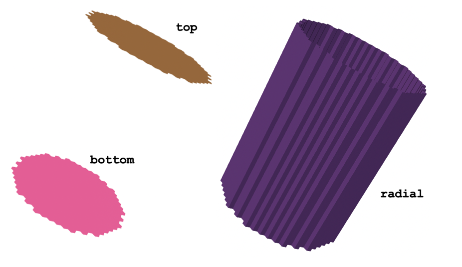
[]Extrude 2D core to 3D
Extrude 2D mesh to 3D (in + direction )
Split into multiple intervals, definite heights and number of layers for each
Set top/bottom boundary IDs to be referenced later
Assign new block IDs to each axial level using "subdomain_swaps"
[Mesh<<<{"href": "../../../../syntax/Mesh/index.html"}>>>]
  [extrude]
    type = AdvancedExtruderGenerator<<<{"description": "Extrudes a 1D mesh into 2D, or a 2D mesh into 3D, and supports a variable height for each elevation, variable number of layers within each elevation, variable growth factors of axial element sizes within each elevation and remap subdomain_ids, boundary_ids and element extra integers within each elevation as well as interface boundaries between neighboring elevation layers, as well as following a 1D curve and modifying the radial (normal to the extrusion axis) extent of the geometry.", "href": "../../../../source/meshgenerators/AdvancedExtruderGenerator.html"}>>>
    input<<<{"description": "The mesh to extrude"}>>> = del_dummy
    heights<<<{"description": "The height of each elevation"}>>> = '50.24 42.32 17.98 16.88 16.88 16.88 16.89 16.88 19.76 65.66 31.14 30.15'
    num_layers<<<{"description": "The number of layers for each elevation - must be num_elevations in length!"}>>> = '3 2 1 1 1 1 1 1 1 4 2 2'
    direction<<<{"description": "A vector that points in the direction to extrude (note, this will be normalized internally - so don't worry about it here)"}>>> = '0 0 1'
    top_boundary<<<{"description": "The boundary name to set on the top boundary. If omitted an ID will be generated."}>>> = 998
    bottom_boundary<<<{"description": "The boundary name to set on the bottom boundary. If omitted an ID will be generated."}>>> = 999

    # This changes the block (subdomain) IDs on each axial layer from the original value (0,1,2,3,4,5,6) to something else
    # There are more than 7 materials in the problem so we introduce new block IDs such as 8,9,10,11,12 to account for different materials.

    # The first row changes the bottom layer block ids 0 1 2 3 4 5 6 to block ids 12 12 12 12 12 11
    subdomain_swaps<<<{"description": "For each row, every two entries are interpreted as a pair of 'from' and 'to' to remap the subdomains for that elevation"}>>> = '0 12 1 12 2 12 3 12 4 12 5 12 6 11;
                       0 9  1 9  2 9  3 8  4 9  5 10 6 11;
                       0 4  1 9  2 9  3 8  4 9  5 10 6 11;
                       0 4  1 1  2 2  3 8  4 3  5 10 6 11;
                       0 4  1 1  2 2  3 8  4 3  5 10 6 11;
                       0 4  1 1  2 2  3 8  4 3  5 10 6 11;
                       0 4  1 1  2 2  3 8  4 3  5 10 6 11;
                       0 5  1 1  2 2  3 8  4 3  5 10 6 11;
                       0 6  1 13 2 13 3 8  4 13 5 10 6 11;
                       0 6  1 14 2 14 3 8  4 14 5 10 6 11;
                       0 7  1 14 2 14 3 8  4 14 5 10 6 11;
                       0 15 1 15 2 15 3 15 4 15 5 15 6 11'
    # The last row changes the block ids on the top layer
  []
[]
Assign Plane-level Reporting IDs
Assign coordinates demarking axial levels in plane_coordinates. These levels should be consistent with how axial levels were defined in AdvancedExtruderGenerator.

[Mesh<<<{"href": "../../../../syntax/Mesh/index.html"}>>>]
  [plane_id]
    type = PlaneIDMeshGenerator<<<{"description": "Adds an extra element integer that identifies planes in a mesh.", "href": "../../../../source/meshgenerators/PlaneIDMeshGenerator.html"}>>>
    input<<<{"description": "The mesh we want to modify"}>>> = extrude
    id_name<<<{"description": "Name of extra integer ID set"}>>> = plane_id # add reporting ids called 'plane_id'
    plane_coordinates<<<{"description": "Coordinates of planes along the axis. The origin are at x/y/z=0 depending on the axis"}>>> = '0.000 50.240 92.560 110.540 127.420
                         144.300 161.180 178.070 194.950
                         214.710 280.370 311.510 341.660' # elements between these coordinates will be labeled with the same plane_id
  []
[]
(Optional) Rename Outer Boundary Sidesets
Griffin requires the outer boundary sidesets to be defined to apply boundary conditions such as vacuum or reflective boundary conditions
[Mesh<<<{"href": "../../../../syntax/Mesh/index.html"}>>>]
  [abtr_mesh]
    type = RenameBoundaryGenerator<<<{"description": "Changes the boundary IDs and/or boundary names for a given set of boundaries defined by either boundary ID or boundary name. The changes are independent of ordering. The merging of boundaries is supported.", "href": "../../../../source/meshgenerators/RenameBoundaryGenerator.html"}>>>
    input<<<{"description": "The mesh we want to modify"}>>> = plane_id
    old_boundary<<<{"description": "Elements with these boundary ID(s)/name(s) will be given the new boundary information specified in 'new_boundary'"}>>> = '999 998' # The old boundary '999' is renamed 'bottom'.
    # The old boundary '998' is renamed 'top'.
    new_boundary<<<{"description": "The new boundary ID(s)/name(s) to be given by the boundary elements defined in 'old_boundary'."}>>> = 'bottom top'
  []
[]
Use of ABTR Mesh in Downstream Physics Code (Griffin)
The Reactor Module creates meshes containing blocks of elements (identified by block ID), groups of elements with similar reporting IDs (identified by different reporting IDs such as pin_id, assembly_id, depletion_id), and groups of curves (2D meshes) or faces (3D meshes) called sidesets (identified by sideset ID). In particular, the blocks and sidesets are used in downstream physics codes to assign materials to mesh elements and to assign boundary conditions.
These assignments are discussed here for Griffin, a MOOSE-based reactor physics code developed under the DOE Nuclear Energy Advanced Modeling and Simulation Program.
Assignment of Material Properties to Blocks
Griffin's MixedNeutronicsMaterial defines the mesh-material mapping explicitly using the subdomain IDs defined on the mesh. Each corresponding material ID defines the cross-section properties for those mesh elements.
The key point is that the block IDs (subdomain_id) in the mesh need to be referenced in the Griffin input file in order to map materials to these blocks. A separate MixedNeutronicsMaterial should be defined in the Griffin input for each unique material ID pertaining to the input mesh.
[Materials<<<{"href": "../../../../syntax/Materials/index.html"}>>>]
  [icore]
    type = MixedNeutronicsMaterial
    material_id = 1
    block = '1'
    isotopes = 'pseudo_ICORE'
  []
[]
Assignment of Boundary Conditions to Sidesets
Griffin requires boundary conditions to be applied to all external boundaries of the mesh (generally the top, bottom, and radial periphery for a typical 3D core). Boundary conditions are set in the TransportSystems block of Griffin. These outer boundary sidesets must be assigned to the appropriate boundary condition type (e.g., VacuumBoundary, ReflectingBoundary, etc.).
[TransportSystems]
  particle = neutron
  G = 33
  VacuumBoundary = 'top bottom radial'
  equation_type = eigenvalue
  [sn]
    scheme = DFEM-SN
    family = L2_LAGRANGE
    order = FIRST
    AQtype = Gauss-Chebyshev
    NPolar = 3
    NAzmthl = 4
    NA = 2
    sweep_type = asynchronous_parallel_sweeper
    using_array_variable = true
    collapse_scattering = true
  []
[]
Generation of CMFD Mesh in Griffin
We briefly touch on mesh generation for the Coarse Mesh Finite Difference (CMFD) acceleration option in Griffin. There are three options:
Option 1: Define "coarse" mesh that is identical to fine mesh
Option 2: Define coarse mesh covering the same geometry as the fine mesh, but with a coarser mesh refinement
Option 3: Define a regular square grid covering the entire mesh domain (and beyond)
This ABTR example uses option 1, where the CMFD acceleration uses the same mesh as the fine mesh, so no additional mesh generation is performed.
So far, the example shown in this section has relied on explicit region ID mappings for the homogeneous core. Section "RGMB Example: Heterogeneous to Homogeneous Conversion for Fast Reactor Core" will explore how the Reactor Geometry Mesh Builder can be used to generate the heterogeneous input mesh and automatically define the homogeneous core mesh from the heterogeneous mesh specifications.
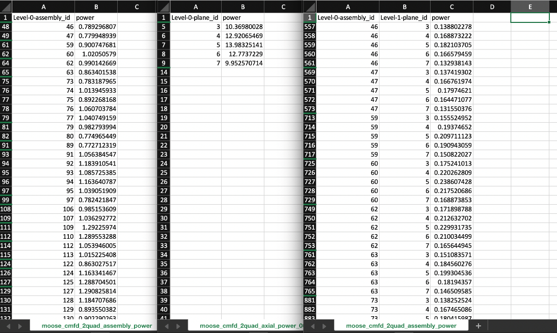
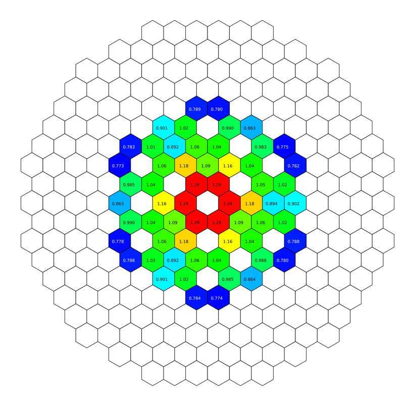
Output Postprocessing
For each ExtraIDIntegralVectorPostprocessor, a separate CSV file is generated to describe the integral variable quantity as a function of each combination of input reporting ID provided. Alternatively, ExtraIDIntegralReporter can output in JSON file format, which is more suitable for additional data parsing using script languages.
[PowerDensity]
  power_density_variable = power
  power = 60.0
[]

[VectorPostprocessors<<<{"href": "../../../../syntax/VectorPostprocessors/index.html"}>>>]
  [assembly_power_2d]
    type = ExtraIDIntegralVectorPostprocessor<<<{"description": "Integrates or averages variables based on extra element IDs", "href": "../../../../source/vectorpostprocessors/ExtraIDIntegralVectorPostprocessor.html"}>>>
    variable<<<{"description": "The names of the variables that this VectorPostprocessor operates on"}>>> = 'power'
    id_name<<<{"description": "List of extra element ID names by which to separate integral(s)."}>>> = 'assembly_id'
  []
  [axial_power]
    type = ExtraIDIntegralVectorPostprocessor<<<{"description": "Integrates or averages variables based on extra element IDs", "href": "../../../../source/vectorpostprocessors/ExtraIDIntegralVectorPostprocessor.html"}>>>
    variable<<<{"description": "The names of the variables that this VectorPostprocessor operates on"}>>> = 'power'
    id_name<<<{"description": "List of extra element ID names by which to separate integral(s)."}>>> = 'plane_id'
  []
  [assembly_power_3d]
    type = ExtraIDIntegralVectorPostprocessor<<<{"description": "Integrates or averages variables based on extra element IDs", "href": "../../../../source/vectorpostprocessors/ExtraIDIntegralVectorPostprocessor.html"}>>>
    variable<<<{"description": "The names of the variables that this VectorPostprocessor operates on"}>>> = 'power'
    id_name<<<{"description": "List of extra element ID names by which to separate integral(s)."}>>> = 'assembly_id plane_id'
  []
[]
Output Postprocessing
For each ExtraIDIntegralVectorPostprocessor, a separate CSV file is generated to describe the integral variable quantity as a function of each combination of input reporting ID provided. Alternatively, ExtraIDIntegralReporter can output in JSON file format, which is more suitable for additional data parsing using script languages.
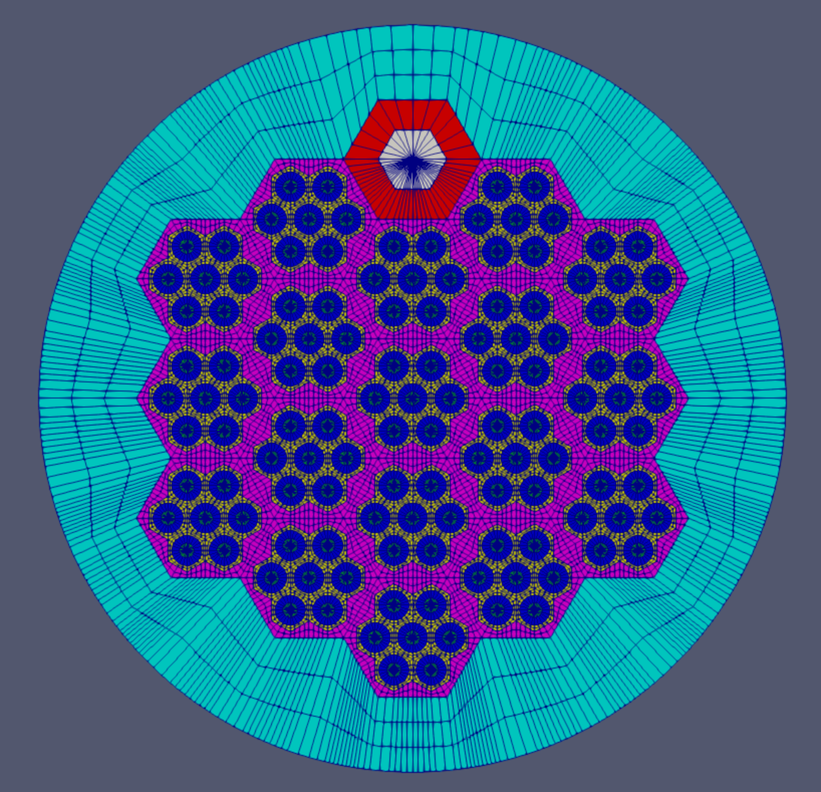
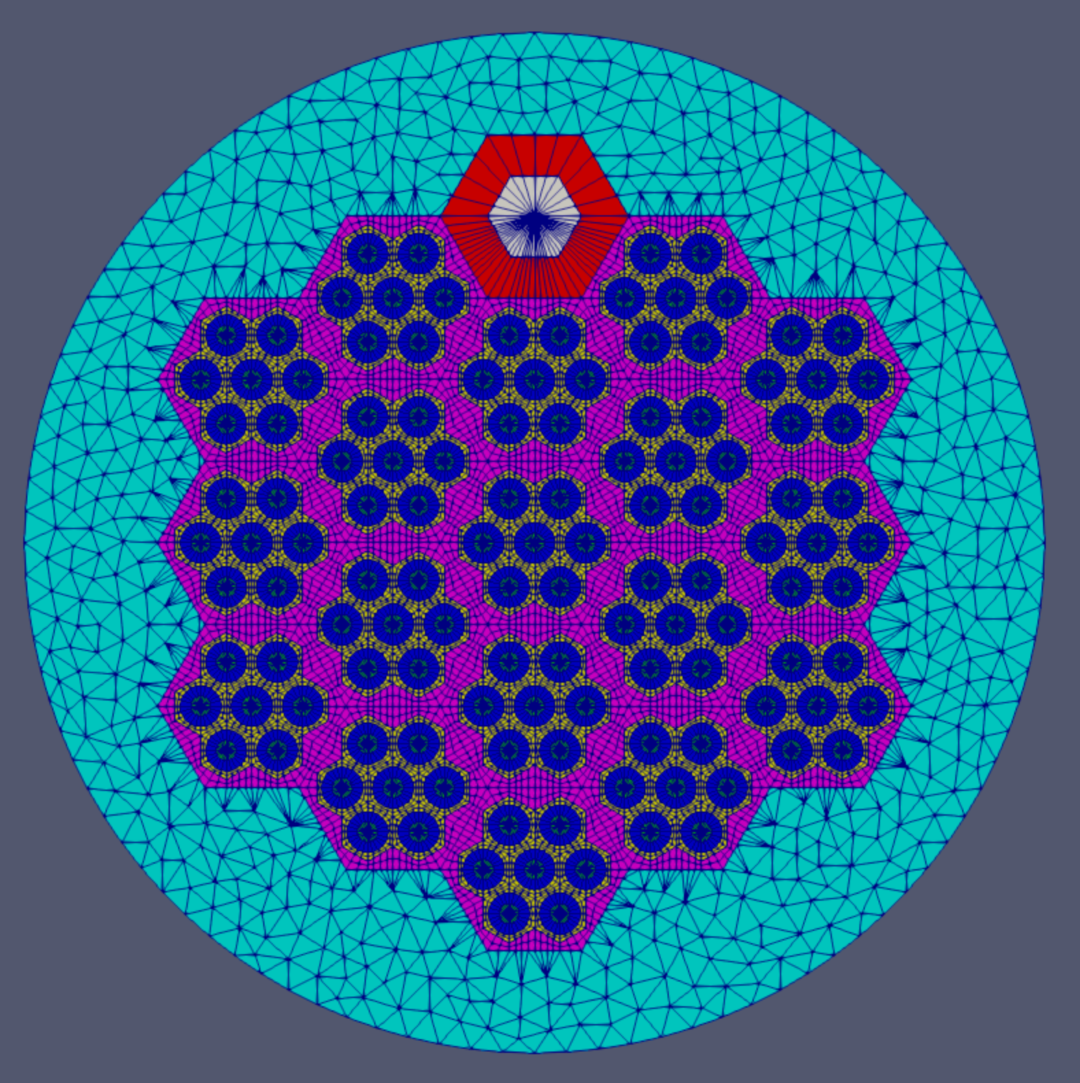
Example: Heat Pipe-Cooled Micro Reactor (HP-MR)
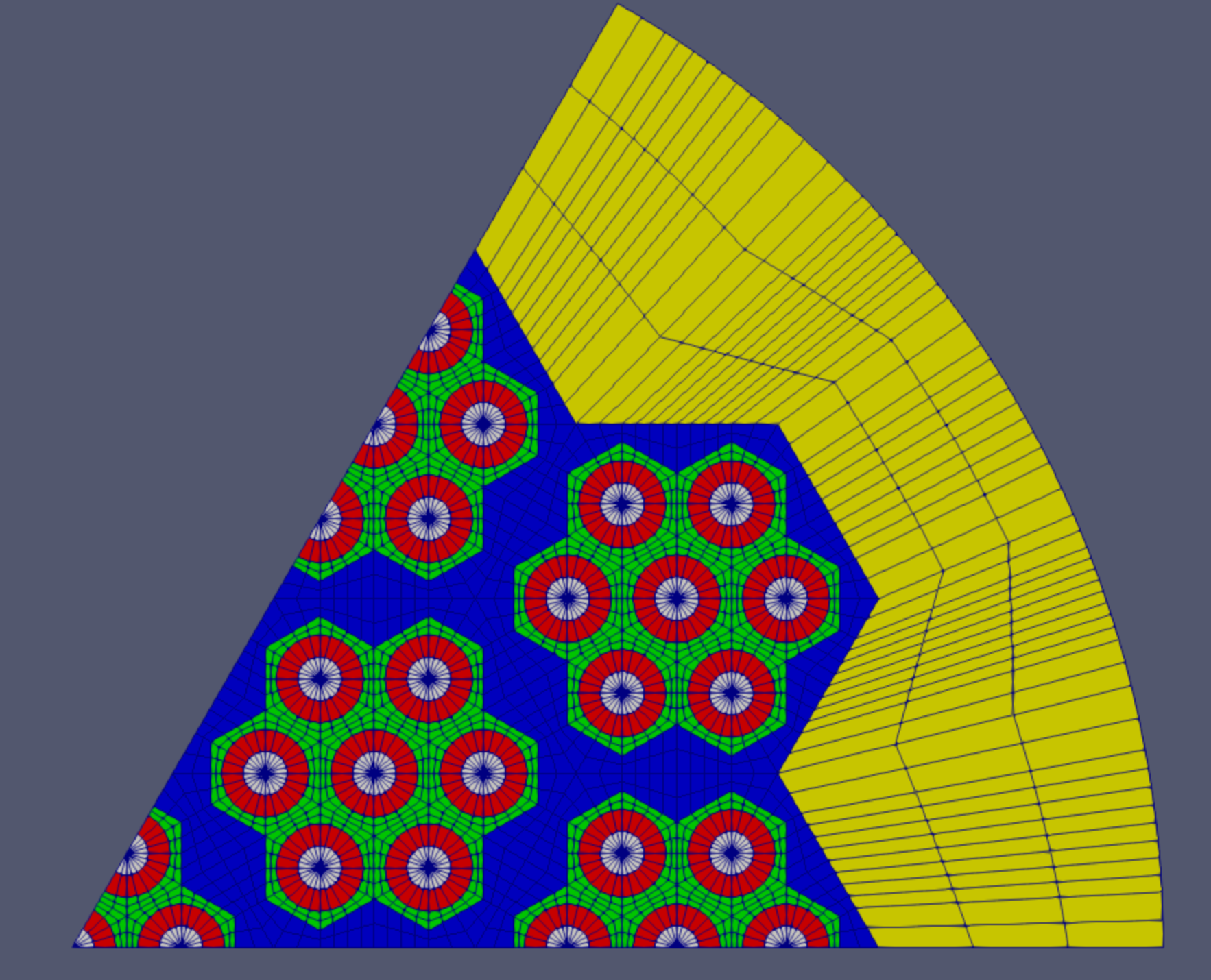
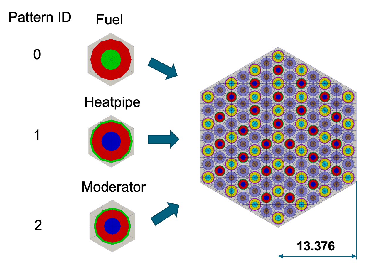
Heat Pipe-Cooled Micro Reactor (HP-MR)
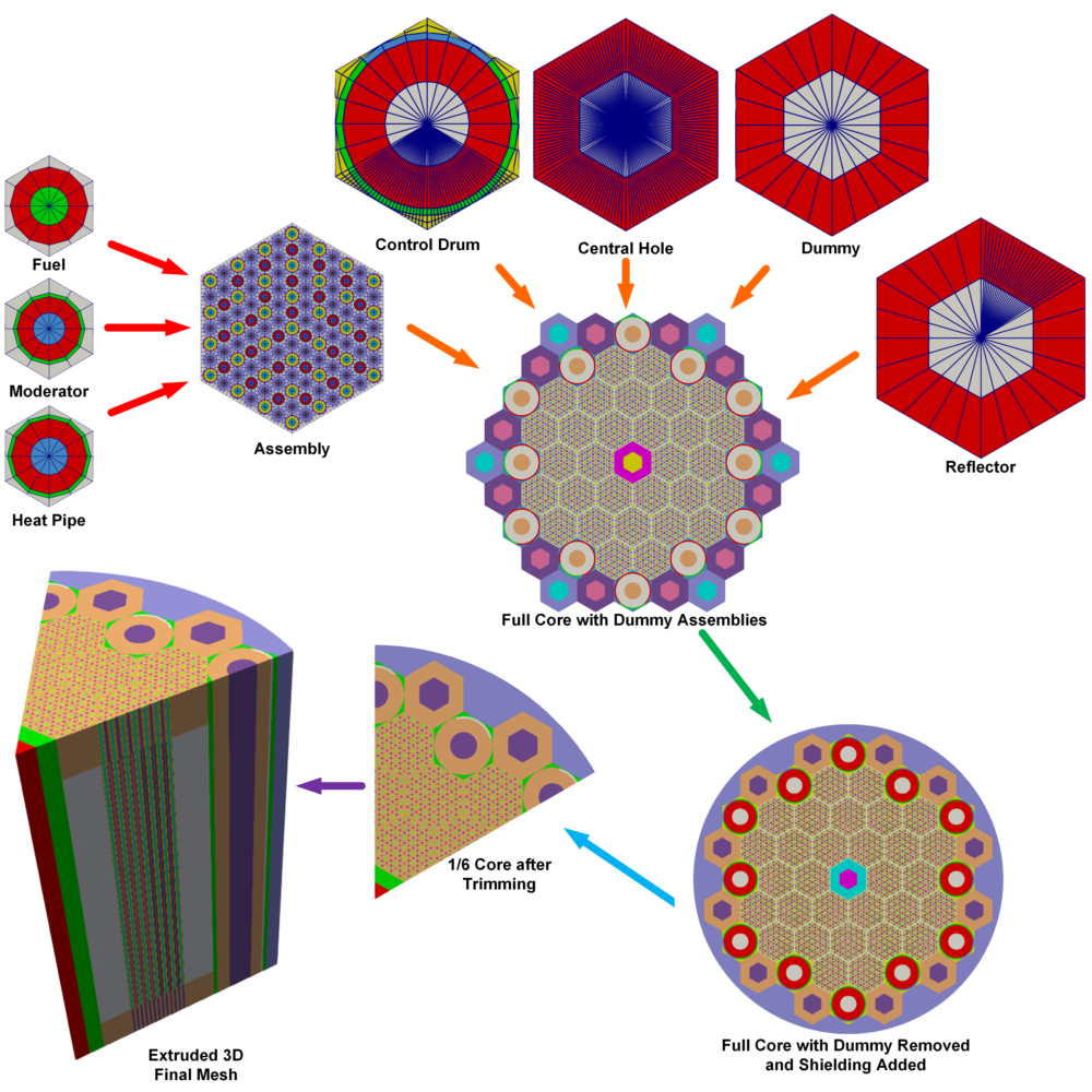
This section covers the creation of a detailed 1/6 core Heat-Pipe Micro Reactor mesh using the following key steps:
Create fuel/moderator/heat-pipe pin cells
Combine pins into a fuel assembly
Create control drum assembly
Create additional assemblies (reflector, central hole, dummies)
Combine assemblies into a full core
Delete dummy assemblies
Add a core periphery region
Slice full core to 1/6 core
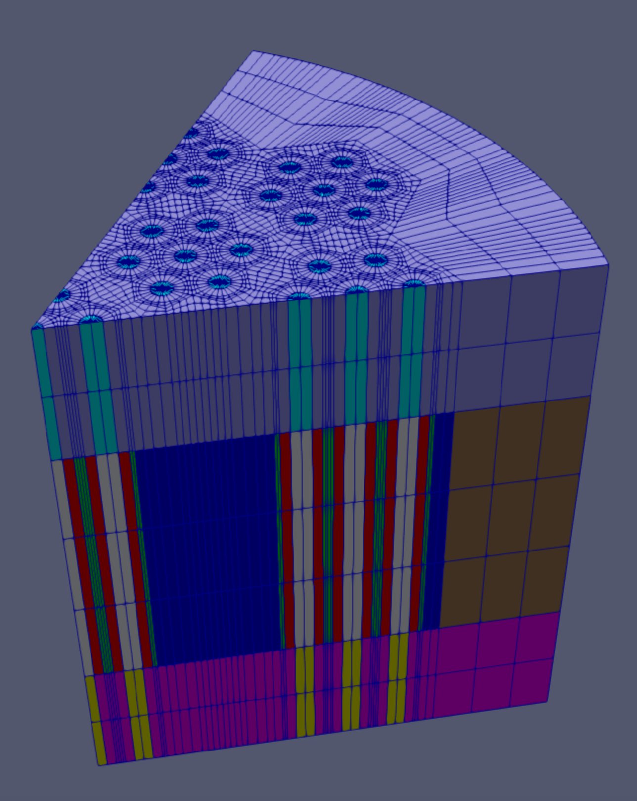
Extrude 2D mesh to 3D
Hands-on package MOOSE input file: tutorials/tutorial04_meshing/doc/listings/reactor_examples/hpmr/hpmr.i
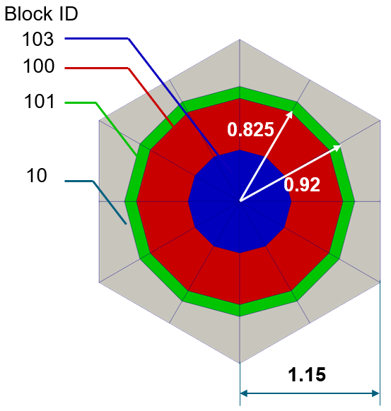
Create Pin Unit Cell
Center, outer ring, background region
Volumes preserved ("preserve_volumes"=
True)TRI center elements ("quad_center_elements"=
False)Center of pin unit cell can be meshed by triangular or quadratic elements
Duct regions can also be added to the outer periphery (not used in this example)
Block IDs are assigned for each radial layer
[Mesh<<<{"href": "../../../../syntax/Mesh/index.html"}>>>]
  [moderator_pincell]
    type = PolygonConcentricCircleMeshGenerator<<<{"description": "This PolygonConcentricCircleMeshGenerator object is designed to mesh a polygon geometry with optional rings centered inside.", "href": "../../../../source/meshgenerators/PolygonConcentricCircleMeshGenerator.html"}>>>
    num_sides<<<{"description": "Number of sides of the polygon."}>>> = 6 # must be six to use hex pattern
    num_sectors_per_side<<<{"description": "Number of azimuthal sectors per polygon side (rotating counterclockwise from top right face)."}>>> = '2 2 2 2 2 2 '
    background_intervals<<<{"description": "Number of radial meshing intervals in background region (area between rings and ducts) excluding the background's boundary layers."}>>> = 1
    background_block_ids<<<{"description": "Optional customized block id for the background block."}>>> = '10'
    polygon_size<<<{"description": "Size of the polygon to be generated (given as either apothem or radius depending on polygon_size_style)."}>>> = 1.15
    polygon_size_style<<<{"description": "Style in which polygon size is given (default: apothem)."}>>> = 'apothem'
    ring_radii<<<{"description": "Radii of major concentric circles (rings)."}>>> = '0.825 0.92'
    ring_intervals<<<{"description": "Number of radial mesh intervals within each major concentric circle excluding their boundary layers."}>>> = '2 1'
    ring_block_ids<<<{"description": "Optional customized block ids for each ring geometry block."}>>> = '103 100 101' # 103 is tri mesh
    preserve_volumes<<<{"description": "Volume of concentric circles can be preserved using this function."}>>> = on
    quad_center_elements<<<{"description": "Whether the center elements are quad or triangular."}>>> = false
  []
[]
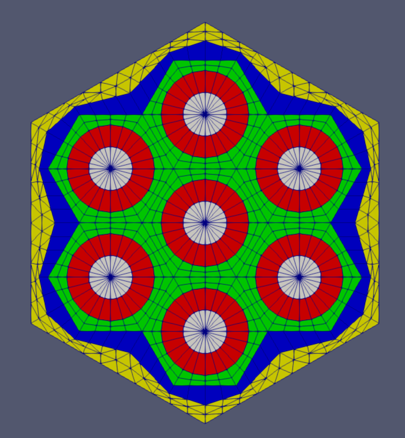
Create Patterned Hexagonal Fuel Assembly
Hexagonal grid (13.376 units apothem )
3 input pin types (fuel, heatpipe, moderator)
Background region out to hexagonal boundary
Pattern references input mesh list in order (0-indexed)
[Mesh<<<{"href": "../../../../syntax/Mesh/index.html"}>>>]
  [fuel_assembly]
    type = PatternedHexMeshGenerator<<<{"description": "This PatternedHexMeshGenerator source code assembles hexagonal meshes into a hexagonal grid and optionally forces the outer boundary to be hexagonal and/or adds a duct.", "href": "../../../../source/meshgenerators/PatternedHexMeshGenerator.html"}>>>
    inputs<<<{"description": "The input MeshGenerators."}>>> = 'fuel_pincell heatpipe_pincell moderator_pincell'
    hexagon_size<<<{"description": "Size of the outmost hexagon boundary to be generated; this is required only when pattern type is 'hexagon'."}>>> = 13.376
    background_block_id<<<{"description": "Optional customized block id for the background block in 'assembly' mode; must be provided along with 'duct_block_ids' if 'duct_sizes' is provided."}>>> = 10
    background_intervals<<<{"description": "Radial intervals in the assembly peripheral region."}>>> = 1
    pattern<<<{"description": "A double-indexed hexagonal-shaped array starting with the upper-left corner."}>>> = '1 0 1 0 1 0 1;
              0 2 0 2 0 2 0 0;
             1 0 1 0 1 0 1 2 1;
            0 2 0 2 0 2 0 0 0 0;
           1 0 1 0 1 0 1 2 1 2 1;
          0 2 0 2 0 2 0 0 0 0 0 0;
         1 0 1 0 1 0 1 2 1 2 1 2 1;
          0 2 0 2 0 2 0 0 0 0 0 0;
           1 0 1 0 1 0 1 2 1 2 1;
            0 2 0 2 0 2 0 0 0 0;
             1 0 1 0 1 0 1 2 1;
              0 2 0 2 0 2 0 0;
               1 0 1 0 1 0 1'
  []
[]
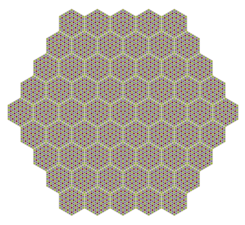
Fuel-Only Core
61 assembly core
Whole core rotated 60 degrees
[Mesh<<<{"href": "../../../../syntax/Mesh/index.html"}>>>]
  [fuel_core]
    type = PatternedHexMeshGenerator<<<{"description": "This PatternedHexMeshGenerator source code assembles hexagonal meshes into a hexagonal grid and optionally forces the outer boundary to be hexagonal and/or adds a duct.", "href": "../../../../source/meshgenerators/PatternedHexMeshGenerator.html"}>>>
    inputs<<<{"description": "The input MeshGenerators."}>>> = 'fuel_assembly'
    # Pattern ID  0
    pattern_boundary<<<{"description": "The boundary shape of the patterned mesh."}>>> = none
    generate_core_metadata<<<{"description": "A Boolean parameter that controls whether the core related metadata is generated for other MOOSE objects such as 'MultiControlDrumFunction' or not."}>>> = true
    pattern<<<{"description": "A double-indexed hexagonal-shaped array starting with the upper-left corner."}>>> = '0 0 0 0 0;
              0 0 0 0 0 0;
             0 0 0 0 0 0 0;
            0 0 0 0 0 0 0 0;
           0 0 0 0 0 0 0 0 0;
            0 0 0 0 0 0 0 0;
             0 0 0 0 0 0 0;
              0 0 0 0 0 0;
               0 0 0 0 0'
    rotate_angle<<<{"description": "Rotate the entire patterned mesh by a certain degrees that is defined here."}>>> = 60
  []
[]
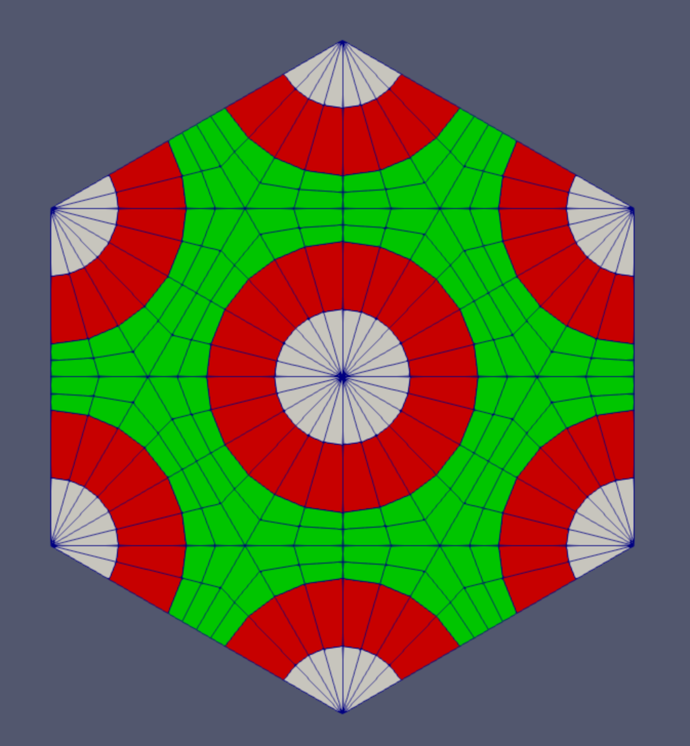
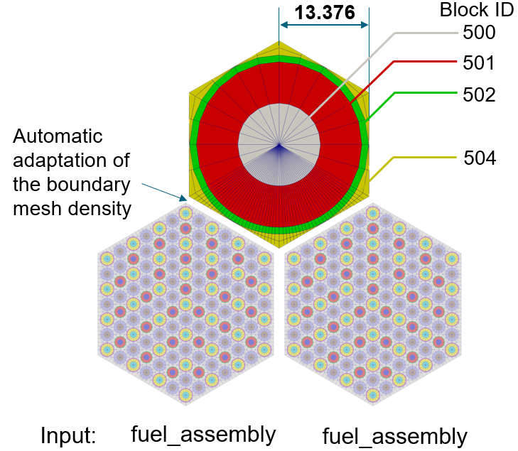
Control Drum Assembly
Define control drum mesh with HexagonConcentricCircleAdaptiveBoundaryMeshGenerator
Split outer ring into 2 separate block IDs using AzimuthalBlockSplitGenerator to account for control material zone
Setup
3 regions (Center region, Absorber Ring, Hexagonal background)
Circular volumes preserved regardless of meshing fidelity ("preserve_volumes"=
true)Side node adaptation performed for instances with neighboring fuel assemblies
HexagonConcentricCircleAdaptiveBoundaryMeshGenerator is used in this case to create a "single pin" hexagonal assembly with sides matching another mesh
Control Drum Assembly
[Mesh<<<{"href": "../../../../syntax/Mesh/index.html"}>>>]
  [cd1_step1]
    type = HexagonConcentricCircleAdaptiveBoundaryMeshGenerator<<<{"description": "This HexagonConcentricCircleAdaptiveBoundaryMeshGenerator object is designed to generate hexagonal meshes with adaptive boundary to facilitate stitching.", "href": "../../../../source/meshgenerators/HexagonConcentricCircleAdaptiveBoundaryMeshGenerator.html"}>>>
    meshes_to_adapt_to<<<{"description": "The name list of the input meshes to adapt to."}>>> = 'fuel_assembly fuel_assembly'
    sides_to_adapt<<<{"description": "List of the hexagon reference side indices that correspond to the sides that need adaptive meshing. The meshes to adapt these sides to are provided in 'inputs'."}>>> = '3 4'
    num_sectors_per_side<<<{"description": "Number of azimuthal sectors per polygon side (rotating counterclockwise from top right face)."}>>> = '4 4 4 4 4 4'
    hexagon_size<<<{"description": "Size of the hexagon to be generated."}>>> = 13.376
    background_intervals<<<{"description": "Number of radial meshing intervals in background region (area between rings and ducts) excluding the background's boundary layers."}>>> = 2
    background_block_ids<<<{"description": "Optional customized block id for the background block."}>>> = 504
    ring_radii<<<{"description": "Radii of major concentric circles (rings)."}>>> = '12.25 13.25'
    ring_intervals<<<{"description": "Number of radial mesh intervals within each major concentric circle excluding their boundary layers."}>>> = '2 1'
    ring_block_ids<<<{"description": "Optional customized block ids for each ring geometry block."}>>> = '500 501 502'
    preserve_volumes<<<{"description": "Volume of concentric circles can be preserved using this function."}>>> = true
    is_control_drum<<<{"description": "Whether this mesh is for a control drum. The value can be set as 'false' if the user wants to use this object for other components."}>>> = true
  []
[]
[Mesh<<<{"href": "../../../../syntax/Mesh/index.html"}>>>]
  [cd1]
    type = AzimuthalBlockSplitGenerator<<<{"description": "This AzimuthalBlockSplitGenerator object takes in a polygon/hexagon concentric circle mesh and renames blocks on a user-defined azimuthal segment / wedge of the mesh.", "href": "../../../../source/meshgenerators/AzimuthalBlockSplitGenerator.html"}>>>
    input<<<{"description": "The input mesh to be modified."}>>> = cd1_step1
    start_angle<<<{"description": "Starting azimuthal angle of the new block."}>>> = 45
    angle_range<<<{"description": "Azimuthal angle range of the new block."}>>> = 90
    old_blocks<<<{"description": "The list of blocks in the input mesh that need to be modified."}>>> = 502
    new_block_ids<<<{"description": "The block IDs to be used for the new selected azimuthal angle blocks."}>>> = 503
  []
[]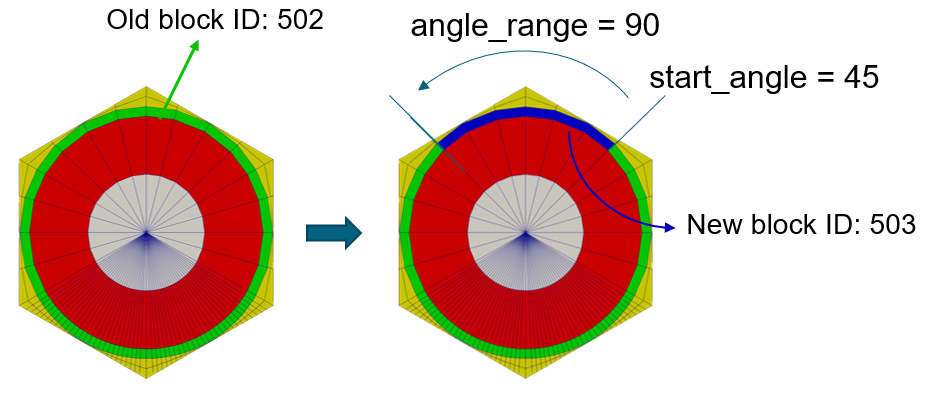
Create Additional Assemblies (Reflector, Air, Dummy)
Same size as fuel assemblies
Side node adaptation for case with neighboring fuel assemblies
Single central air hole assembly
Multiple "Dummy" assemblies needed for patterning (to be deleted later)
Boundary nodes on two neighboring assemblies need to match up in order for the assemblies to be stitched together
Assemblies that neighbor several different assembly types (control drums, reflectors) are generally created last so that the boundaries can be specified based on the meshes these need to match.
[Mesh<<<{"href": "../../../../syntax/Mesh/index.html"}>>>]
  [refl1]
    type = HexagonConcentricCircleAdaptiveBoundaryMeshGenerator<<<{"description": "This HexagonConcentricCircleAdaptiveBoundaryMeshGenerator object is designed to generate hexagonal meshes with adaptive boundary to facilitate stitching.", "href": "../../../../source/meshgenerators/HexagonConcentricCircleAdaptiveBoundaryMeshGenerator.html"}>>>
    meshes_to_adapt_to<<<{"description": "The name list of the input meshes to adapt to."}>>> = 'fuel_assembly'
    sides_to_adapt<<<{"description": "List of the hexagon reference side indices that correspond to the sides that need adaptive meshing. The meshes to adapt these sides to are provided in 'inputs'."}>>> = '4'
    num_sectors_per_side<<<{"description": "Number of azimuthal sectors per polygon side (rotating counterclockwise from top right face)."}>>> = '4 4 4 4 4 4'
    hexagon_size<<<{"description": "Size of the hexagon to be generated."}>>> = 13.376
    background_intervals<<<{"description": "Number of radial meshing intervals in background region (area between rings and ducts) excluding the background's boundary layers."}>>> = 2
    background_block_ids<<<{"description": "Optional customized block id for the background block."}>>> = '400 401'
  []
[]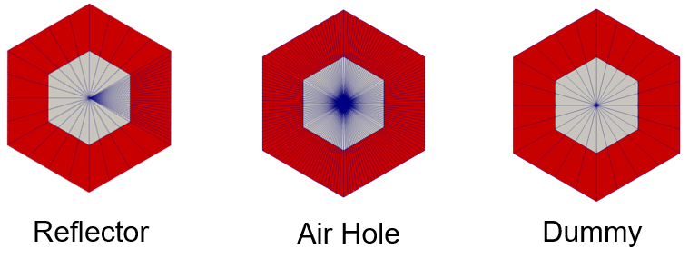
Create Patterned Full Core
Whole core rotated 60 degrees
5 Input geometry types
Fuel assemblies
"Other" Assemblies - Control drum (12 meshes), Reflector (6 meshes), Air hole center
Dummy assemblies
"Empty" spots should be defined with dummy assemblies and later deleted.
[Mesh<<<{"href": "../../../../syntax/Mesh/index.html"}>>>]
  [core]
    type = PatternedHexMeshGenerator<<<{"description": "This PatternedHexMeshGenerator source code assembles hexagonal meshes into a hexagonal grid and optionally forces the outer boundary to be hexagonal and/or adds a duct.", "href": "../../../../source/meshgenerators/PatternedHexMeshGenerator.html"}>>>
    inputs<<<{"description": "The input MeshGenerators."}>>> = 'fuel_assembly cd1 cd2 cd3 cd4 cd5 cd6 cd7 cd8 cd9 cd10 cd11 cd12 refl1 refl2 refl3 refl4 refl5 refl6 dummy air_center'
    # Pattern ID  0           1   2   3   4   5   6   7   8   9   10   11   12    13    14    15    16    17    18   19  20
    pattern_boundary<<<{"description": "The boundary shape of the patterned mesh."}>>> = none
    generate_core_metadata<<<{"description": "A Boolean parameter that controls whether the core related metadata is generated for other MOOSE objects such as 'MultiControlDrumFunction' or not."}>>> = true
    pattern<<<{"description": "A double-indexed hexagonal-shaped array starting with the upper-left corner."}>>> = '19 13 1  18 19;
             13 12  0  0  2 18;
           11  0  0  0  0  0  3;
          14 0  0   0  0  0  0 17;
        19 10  0  0  20  0  0  4 19;
          14 0  0   0  0  0  0 17;
            9  0  0  0  0  0  5;
             15  8  0  0  6 16;
               19 15  7 16 19'
    rotate_angle<<<{"description": "Rotate the entire patterned mesh by a certain degrees that is defined here."}>>> = 60
  []
[]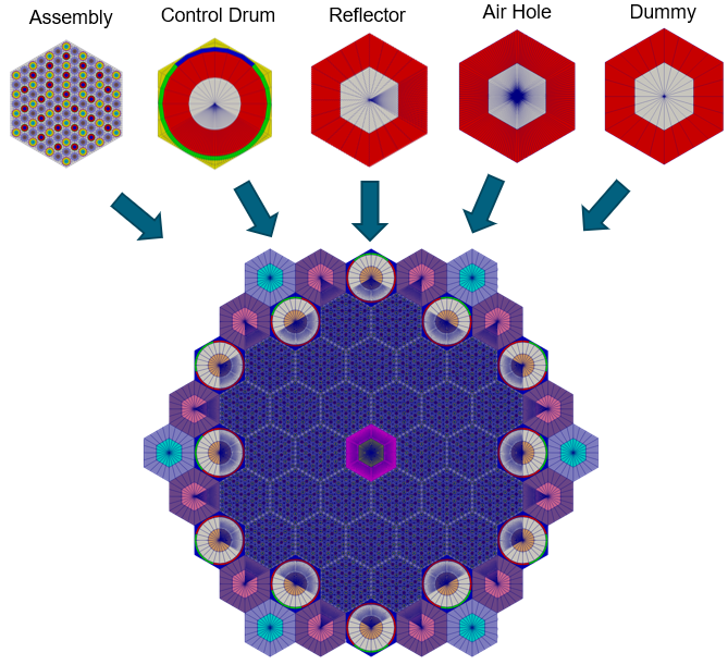
Delete Dummy Assemblies
Remove "dummy" assemblies which were added only for core hex patterning
The blocks IDs of the dummy assembly were defined by the user in the definition of the dummy assembly
Set the new outer boundaries that result from the deleted assemblies to have the same sideset ID as the existing outer boundary
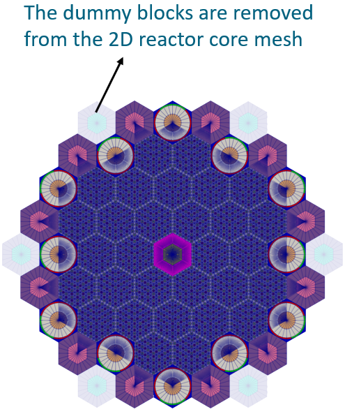
[Mesh<<<{"href": "../../../../syntax/Mesh/index.html"}>>>]
  [del_dummy]
    type = BlockDeletionGenerator<<<{"description": "Mesh generator which removes elements from the specified subdomains", "href": "../../../../source/meshgenerators/BlockDeletionGenerator.html"}>>>
    block<<<{"description": "The list of blocks to be processed (deleted or kept)"}>>> = '700 701'
    input<<<{"description": "The mesh we want to modify"}>>> = core
    new_boundary<<<{"description": "optional boundary name to assign to the cut surface"}>>> = 10000
  []
[]
Add Core Periphery
115.0 units vessel radius
Use existing core outer boundary ID as input boundary which describes which boundary the peripheral ring should start from
[Mesh<<<{"href": "../../../../syntax/Mesh/index.html"}>>>]
  [outer_shield]
    type = PeripheralRingMeshGenerator<<<{"description": "This PeripheralRingMeshGenerator object adds a circular peripheral region to the input mesh.", "href": "../../../../source/meshgenerators/PeripheralRingMeshGenerator.html"}>>>
    input<<<{"description": "The input mesh to be modified."}>>> = del_dummy
    peripheral_layer_num<<<{"description": "The radial layers of the peripheral ring to be added."}>>> = 1
    peripheral_ring_radius<<<{"description": "Radius of the peripheral ring to be added."}>>> = 115.0
    input_mesh_external_boundary<<<{"description": "The external boundary of the input mesh."}>>> = 10000
    peripheral_ring_block_id<<<{"description": "The block id assigned to the created peripheral layer."}>>> = 250
    peripheral_ring_block_name<<<{"description": "The block name assigned to the created peripheral layer."}>>> = outer_shield
  []
[]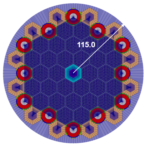
Slice to 1/6 Core
Trimming plane defined by a point and a normal vector
Elements whose centroids lie "above" (in the direction of the normal vector) the plane will be deleted
Set new outer boundary ID on sliced lines to be referenced later
To slice the full core in half:
Point = , normal =
To slice the half core into 1/3:
Point = , normal =
Advanced trimming options are available (see HexagonMeshTrimmer). Trimming should only be performed along lines of symmetry.
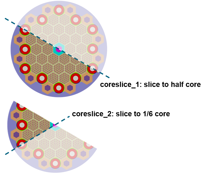
[Mesh<<<{"href": "../../../../syntax/Mesh/index.html"}>>>]
  [coreslice_1]
    type = PlaneDeletionGenerator<<<{"description": "Removes elements lying 'above' the plane (in the direction of the normal).", "href": "../../../../source/meshgenerators/PlaneDeletionGenerator.html"}>>>
    point<<<{"description": "The point that defines the plane"}>>> = '0 0 0'
    normal<<<{"description": "The normal that defines the plane"}>>> = '10 17.32 0'
    input<<<{"description": "The mesh we want to modify"}>>> = outer_shield
    new_boundary<<<{"description": "optional boundary name to assign to the cut surface"}>>> = 147
  []
[]
[Mesh<<<{"href": "../../../../syntax/Mesh/index.html"}>>>]
[coreslice_2]
type = PlaneDeletionGenerator<<<{"description": "Removes elements lying 'above' the plane (in the direction of the normal).", "href": "../../../../source/meshgenerators/PlaneDeletionGenerator.html"}>>>
point<<<{"description": "The point that defines the plane"}>>> = '0 0 0'
normal<<<{"description": "The normal that defines the plane"}>>> = '10 -17.32 0'
input<<<{"description": "The mesh we want to modify"}>>> = coreslice_1
new_boundary<<<{"description": "optional boundary name to assign to the cut surface"}>>> = 147
[]
[]Extrude to 3D
Extrude the 2D mesh in + direction
Split into 3 axial intervals
Heights for each interval: 20 units, 160 units, 20 units
Number of layers in each interval: 1, 8, 1
Set top/bottom boundary IDs to be referenced later
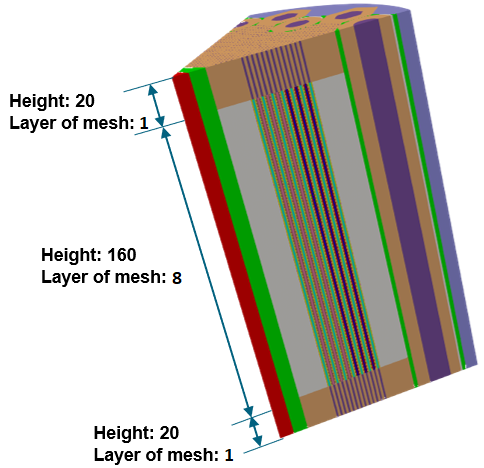
[Mesh<<<{"href": "../../../../syntax/Mesh/index.html"}>>>]
  [extrude]
    type = AdvancedExtruderGenerator<<<{"description": "Extrudes a 1D mesh into 2D, or a 2D mesh into 3D, and supports a variable height for each elevation, variable number of layers within each elevation, variable growth factors of axial element sizes within each elevation and remap subdomain_ids, boundary_ids and element extra integers within each elevation as well as interface boundaries between neighboring elevation layers, as well as following a 1D curve and modifying the radial (normal to the extrusion axis) extent of the geometry.", "href": "../../../../source/meshgenerators/AdvancedExtruderGenerator.html"}>>>
    input<<<{"description": "The mesh to extrude"}>>> = coreslice_2
    heights<<<{"description": "The height of each elevation"}>>> = '20 160 20'
    num_layers<<<{"description": "The number of layers for each elevation - must be num_elevations in length!"}>>> = '1 8 1'
    direction<<<{"description": "A vector that points in the direction to extrude (note, this will be normalized internally - so don't worry about it here)"}>>> = '0 0 1'
    subdomain_swaps<<<{"description": "For each row, every two entries are interpreted as a pair of 'from' and 'to' to remap the subdomains for that elevation"}>>> = '10 1000 100 1000 101 1000 103 1003 200 1000 201 1000 203 1003 301 1000 303 1003;
                        10 10   100 100  101 101  103 103  200 200  201 201  203 203  301 301  303 303;
                        10 1000 100 1000 101 1000 103 1003 200 200  201 201  203 203  301 1000 303 1003'
    top_boundary<<<{"description": "The boundary name to set on the top boundary. If omitted an ID will be generated."}>>> = 2000
    bottom_boundary<<<{"description": "The boundary name to set on the bottom boundary. If omitted an ID will be generated."}>>> = 3000
  []
[]
Using the Mesh in Downstream Physics Applications (Griffin)
We briefly describe some key steps which are required to use the resulting mesh in Griffin. Namely, block IDs (subdomain_id) are referenced in Griffin to assign materials to elements. The external boundary sideset IDs are referenced in Griffin to assign boundary conditions.
Assignment of Material Properties to Blocks
All blocks in the mesh must be assigned to a material in Griffin.
[Materials<<<{"href": "../../../../syntax/Materials/index.html"}>>>]
  [mat1]
    type = CoupledFeedbackNeutronicsMaterial
    block = '250'
    material_id = 1
  []
  [mat2]
    type = CoupledFeedbackNeutronicsMaterial
    block = '600'
    material_id = 2
  []
  # Repeat for all other blocks in mesh
[]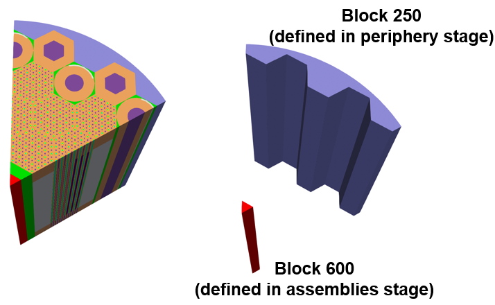
Assignment of Boundary Conditions to Sidesets
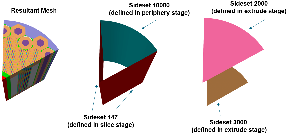
Generation of Coarse Mesh in Griffin
We briefly touch on mesh generation for the Coarse Mesh Finite Difference acceleration option in Griffin. There are three options:
Option 1: Define "coarse" mesh that is identical to fine mesh
Option 2: Define coarse mesh covering the same geometry as the fine mesh but with a coarser mesh refinement
Option 3: Define a regular square grid covering the entire mesh domain (and beyond)
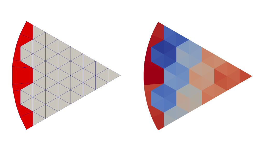
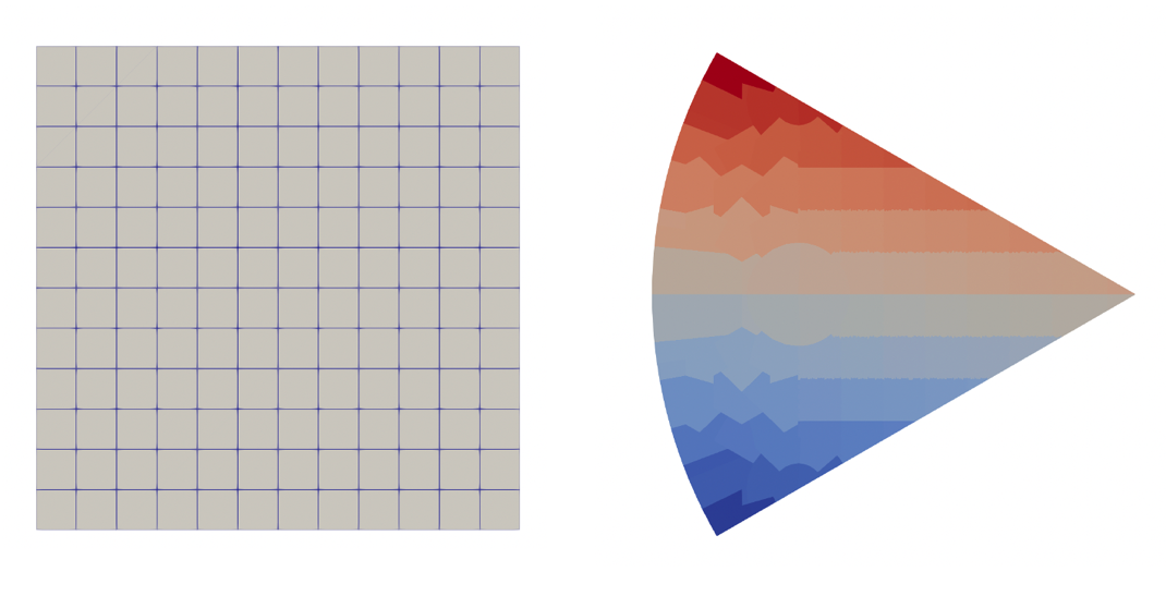
Reactor Geometry Mesh Builder (RGMB): A Contained System for Building Regular Geometries
Reactor Geometry Mesh Builder (RGMB) refers to a subset of specialized mesh generators designed specifically for simplifying the task of building reactor geometries. These mesh generators are intended to be called in a specific order and assume that pin-like structures are built into a Cartesian or hexagonal assembly lattice. These assembly lattices can be combined into a core lattice with a peripheral ring added to the core boundary. RGMB mesh generation is accomplished by calling base Reactor module mesh generators under-the-hood while exposing only the minimum number of parameters needed by the user to define the reactor geometry.
Benefits of RGMB system include:
Simplified user options for generation of reactor meshes
Minimal number of blocks associated with output mesh – one block is allocated to all quadrilateral elements and another block is used for all triangular elements
Automatic assignment of extra element integers:
pin_id,assembly_id,plane_idAssignment of region ids directly on the mesh, avoiding the need to define these map materials to mesh in the MOOSE physics application input file
The RGMB system is useful for regular 2D or extruded 3D Cartesian or hexagonal geometries. Many useful meshing options (e.g., boundary layers) are currently hidden and unavailable to the user through RGMB to keep things simple. If these options are needed for more complex geometries, the individual Reactor Module mesh generators should be used as shown in earlier sections. Additionally, control drum mesh generation support has been added for hexagonal core layouts.
ReactorMeshParams
ReactorMeshParams acts as a container for storing global data about the reactor geometry that needs to be retrieved at different stages of the RGMB mesh generation workflow. In particular, the union axial grid for the extruded geometry is defined here and propagated to the entire mesh upon the extrusion step.
[Mesh<<<{"href": "../../../../syntax/Mesh/index.html"}>>>]
  [rmp]
    type = ReactorMeshParams<<<{"description": "This ReactorMeshParams object acts as storage for persistent information about the reactor geometry.", "href": "../../../../source/meshgenerators/ReactorMeshParams.html"}>>>
    dim<<<{"description": "The dimension of the mesh to be generated"}>>> = 3
    geom<<<{"description": "The geometry type of the reactor mesh"}>>> = "Square"
    assembly_pitch<<<{"description": "Center to center distance of assemblies"}>>> = 2.84126
    axial_regions<<<{"description": "Length of each axial region"}>>> = '1.0'
    axial_mesh_intervals<<<{"description": "Number of elements in the Z direction for each axial region"}>>> = '1'
    top_boundary_id<<<{"description": "The boundary ID to set on top boundary of the extruded mesh"}>>> = 201
    bottom_boundary_id<<<{"description": "The boundary ID to set on bottom boundary of the extruded mesh"}>>> = 202
    radial_boundary_id<<<{"description": "The boundary ID to set on the outer radial boundary of a CoreMeshGenerator object"}>>> = 200
  []
[]
PinMeshGenerator
PinMeshGenerator calls PolygonConcentricCircleMeshGenerator to generate a Cartesian or hexagonal pin-like structure (pin, background, and duct) (mesh colored by subdomain_id (left) and region_id (right))
[Mesh<<<{"href": "../../../../syntax/Mesh/index.html"}>>>]
  [pin1]
    type = PinMeshGenerator<<<{"description": "This PinMeshGenerator object is designed to generate pin-like structures, with IDs, from a reactor geometry. Whether it be a square or hexagonal pin, they are divided into three substructures - the innermost radial pin regions, the single bridging background region, and the square or hexagonal ducts regions.", "href": "../../../../source/meshgenerators/PinMeshGenerator.html"}>>>
    reactor_params<<<{"description": "The ReactorMeshParams MeshGenerator that is the basis for this component conformal mesh."}>>> = rmp
    pin_type<<<{"description": "The integer ID for this pin type definition"}>>> = 1
    pitch<<<{"description": "The pitch for the outermost boundary polygon"}>>> = 1.42063
    num_sectors<<<{"description": "Number of azimuthal sectors in each quadrant"}>>> = 2
    ring_radii<<<{"description": "Radii of major concentric circles of the pin. If unspecified, no pin is present."}>>> = 0.2
    duct_halfpitch<<<{"description": "Apothem of the ducts. If unspecified, no duct is present."}>>> = 0.58
    mesh_intervals<<<{"description": "The number of meshing intervals for each region starting at the center. Parameter should be size:((length(ring_radii) + length(duct_halfpitch) + 1"}>>> = '1 1 1'
    region_ids<<<{"description": "IDs for each radial and axial zone for assignment of region_id extra element id. Inner indexing is radial zones (pin/background/duct), outer indexing is axial"}>>> = '1 2 5'
    quad_center_elements<<<{"description": "Whether the center elements are quad or triangular."}>>> = true
  []
[]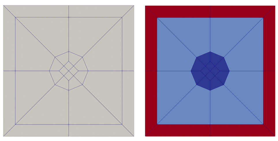
[Mesh<<<{"href": "../../../../syntax/Mesh/index.html"}>>>]
  [pin1]
    type = PinMeshGenerator<<<{"description": "This PinMeshGenerator object is designed to generate pin-like structures, with IDs, from a reactor geometry. Whether it be a square or hexagonal pin, they are divided into three substructures - the innermost radial pin regions, the single bridging background region, and the square or hexagonal ducts regions.", "href": "../../../../source/meshgenerators/PinMeshGenerator.html"}>>>
    reactor_params<<<{"description": "The ReactorMeshParams MeshGenerator that is the basis for this component conformal mesh."}>>> = rmp
    pin_type<<<{"description": "The integer ID for this pin type definition"}>>> = 1
    pitch<<<{"description": "The pitch for the outermost boundary polygon"}>>> = 1.42063
    num_sectors<<<{"description": "Number of azimuthal sectors in each quadrant"}>>> = 2
    ring_radii<<<{"description": "Radii of major concentric circles of the pin. If unspecified, no pin is present."}>>> = 0.2
    duct_halfpitch<<<{"description": "Apothem of the ducts. If unspecified, no duct is present."}>>> = 0.58
    mesh_intervals<<<{"description": "The number of meshing intervals for each region starting at the center. Parameter should be size:((length(ring_radii) + length(duct_halfpitch) + 1"}>>> = '1 1 1'
    region_ids<<<{"description": "IDs for each radial and axial zone for assignment of region_id extra element id. Inner indexing is radial zones (pin/background/duct), outer indexing is axial"}>>> = '1 2 3'
    quad_center_elements<<<{"description": "Whether the center elements are quad or triangular."}>>> = false
  []
[]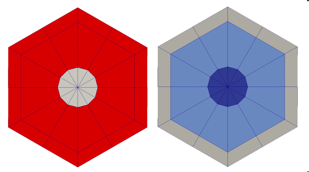
AssemblyMeshGenerator
AssemblyMeshGenerator calls PatternedHexMeshGenerator or PatternedMeshGenerator to generate a Cartesian or hexagonal lattice of pin-like structures. (assembly colored by subdomain_id (left), region_id (middle), and pin_id (right))
[Mesh<<<{"href": "../../../../syntax/Mesh/index.html"}>>>]
  [assembly1]
    type = AssemblyMeshGenerator<<<{"description": "This AssemblyMeshGenerator object is designed to generate assembly-like structures, with IDs, from a reactor geometry. The assembly-like structures must consist of a full pattern of equal sized pins from PinMeshGenerator. A hexagonal assembly will be placed inside of a bounding hexagon consisting of a background region and, optionally, duct regions.", "href": "../../../../source/meshgenerators/AssemblyMeshGenerator.html"}>>>
    assembly_type<<<{"description": "The integer ID for this assembly type definition"}>>> = 2
    inputs<<<{"description": "The PinMeshGenerators that form the components of the assembly."}>>> = 'pin3 pin1 pin2'
    pattern<<<{"description": "A double-indexed array starting with the upper-left corner where the indexrepresents the layout of input pins in the assembly lattice."}>>> = '0 1;
               1 2'
  []
[]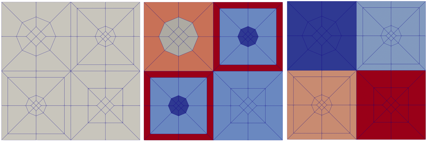
[Mesh<<<{"href": "../../../../syntax/Mesh/index.html"}>>>]
  [assembly1]
    type = AssemblyMeshGenerator<<<{"description": "This AssemblyMeshGenerator object is designed to generate assembly-like structures, with IDs, from a reactor geometry. The assembly-like structures must consist of a full pattern of equal sized pins from PinMeshGenerator. A hexagonal assembly will be placed inside of a bounding hexagon consisting of a background region and, optionally, duct regions.", "href": "../../../../source/meshgenerators/AssemblyMeshGenerator.html"}>>>
    assembly_type<<<{"description": "The integer ID for this assembly type definition"}>>> = 1
    inputs<<<{"description": "The PinMeshGenerators that form the components of the assembly."}>>> = 'pin1 pin2 pin3'
    pattern<<<{"description": "A double-indexed array starting with the upper-left corner where the indexrepresents the layout of input pins in the assembly lattice."}>>> = '1 2;
              2 0 1;
               1 2'
    background_intervals<<<{"description": "Radial intervals in the assembly peripheral region."}>>> = 1
    background_region_id<<<{"description": "The region id for the background area between the pins and the ducts to set region_id extra-element integer"}>>> = 7
    duct_intervals<<<{"description": "Number of meshing intervals in each enclosing duct."}>>> = 1
    duct_halfpitch<<<{"description": "Distance(s) from center to duct(s) inner boundaries."}>>> = 2.2
    duct_region_ids<<<{"description": "The region id for the ducts from innermost to outermost, to set region_id extra-element integer."}>>> = 8
  []
[]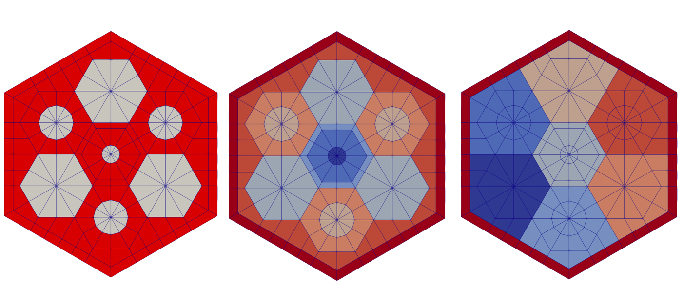
CoreMeshGenerator
CoreMeshGenerator calls PatternedHexMeshGenerator or PatternedMeshGenerator to generate a Cartesian or hexagonal lattice of assembly-like structures. (core colored by subdomain_id (left), region_id (middle), and assembly_id (right))
[Mesh<<<{"href": "../../../../syntax/Mesh/index.html"}>>>]
  [rgmb_core]
    type = CoreMeshGenerator<<<{"description": "This CoreMeshGenerator object is designed to generate a core-like structure, with IDs, from a reactor geometry. The core-like structure consists of a pattern of assembly-like structures generated with AssemblyMeshGenerator and/or ControlDrumMeshGenerator and is permitted to have \"empty\" locations. The size and spacing of the assembly-like structures is defined, and enforced by declaration in the ReactorMeshParams.", "href": "../../../../source/meshgenerators/CoreMeshGenerator.html"}>>>
    inputs<<<{"description": "The AssemblyMeshGenerator and ControlDrumMeshGenerator objects that form the components of the assembly."}>>> = 'assembly1 assembly2'
    pattern<<<{"description": "A double-indexed array starting with the upper-left corner where the indexrepresents the layout of input assemblies in the core lattice."}>>> = '1 0;
               0 1'
    extrude<<<{"description": "Determines if this is the final step in the geometry construction and extrudes the 2D geometry to 3D. If this is true then this mesh cannot be used in further mesh building in the Reactor workflow"}>>> = true
  []
[]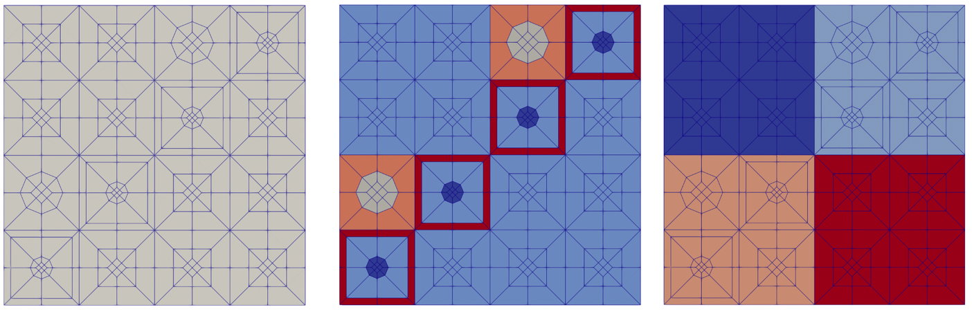
[Mesh<<<{"href": "../../../../syntax/Mesh/index.html"}>>>]
  [rgmb_core]
    type = CoreMeshGenerator<<<{"description": "This CoreMeshGenerator object is designed to generate a core-like structure, with IDs, from a reactor geometry. The core-like structure consists of a pattern of assembly-like structures generated with AssemblyMeshGenerator and/or ControlDrumMeshGenerator and is permitted to have \"empty\" locations. The size and spacing of the assembly-like structures is defined, and enforced by declaration in the ReactorMeshParams.", "href": "../../../../source/meshgenerators/CoreMeshGenerator.html"}>>>
    inputs<<<{"description": "The AssemblyMeshGenerator and ControlDrumMeshGenerator objects that form the components of the assembly."}>>> = 'assembly1 assembly2 empty'
    dummy_assembly_name<<<{"description": "The place holder name in \"inputs\" that indicates an empty position."}>>> = empty
    pattern<<<{"description": "A double-indexed array starting with the upper-left corner where the indexrepresents the layout of input assemblies in the core lattice."}>>> = '2 1;
              1 0 2;
               2 1'
    extrude<<<{"description": "Determines if this is the final step in the geometry construction and extrudes the 2D geometry to 3D. If this is true then this mesh cannot be used in further mesh building in the Reactor workflow"}>>> = true
  []
[]
Flexible Assembly Stitching in RGMB
By default, CoreMeshGenerator does not consider the location of nodes at the boundary of assemblies when stitching the core lattice. For dissimilar assemblies, this can lead to hanging nodes at the assembly interface. The following scenarios can cause hanging nodes in the output core mesh:
1: Two assemblies have the same constituent pin geometry but vary in total number of pins in the pin lattice
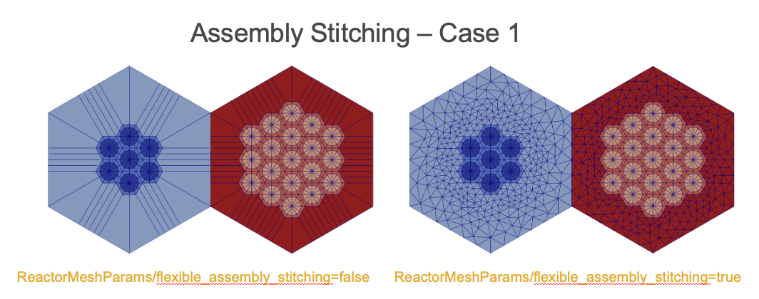
2: Two assemblies have the same pin lattice structure and geometry, but the constituent pins of each assembly are subdivided into a different number of sectors per side.
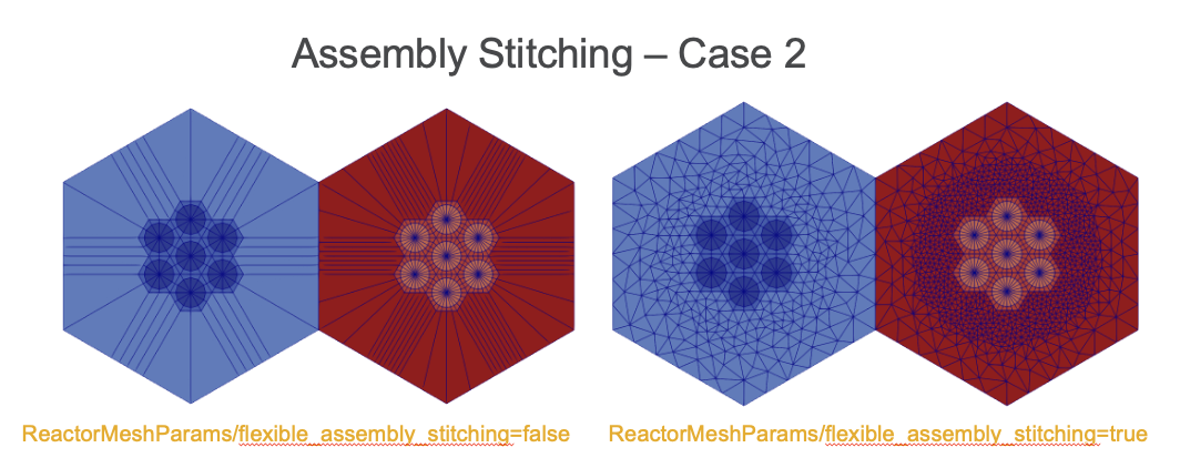
3: One assembly is defined as a heterogeneous mesh (contains one or more pins), and the other assembly is homogenized.
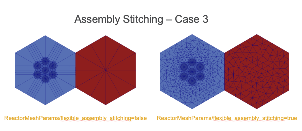
Flexible Assembly Stitching in RGMB (cont'd)
The parameter "flexible_assembly_stitching" in ReactorMeshParams can be set to true to enable flexible assembly stitching, where the outermost radial layer is deleted and re-triangulated in order to ensure the same number of nodes on either side of the assembly interface. The optional parameter "num_sectors_at_flexible_boundary" defines how many sectors should be defined at the assembly interface.
ControlDrumMeshGenerator
ControlDrumMeshGenerator calls AdvancedConcentricCircleGenerator and FlexiblePatternGenerator to generate control drum structures that can be stitched directly into a hexagonal core lattice. This mesh generator supports automatic region ID assignments as well as creation of an explicit drum pad region if desired.
[Mesh<<<{"href": "../../../../syntax/Mesh/index.html"}>>>]
  [drum_nopad]
    type = ControlDrumMeshGenerator<<<{"description": "This ControlDrumMeshGenerator object is designed to generate drum-like structures, with IDs, from a reactor geometry. These structures can be used directly within CoreMeshGenerator to stitchcontrol drums into a core lattice alongside AssemblyMeshGenerator structures", "href": "../../../../source/meshgenerators/ControlDrumMeshGenerator.html"}>>>
    reactor_params<<<{"description": "The ReactorMeshParams MeshGenerator that is the basis for this component mesh."}>>> = rmp
    assembly_type<<<{"description": "The assembly type integer ID to use for this control drum definition. This parameter should be uniquely defined for each ControlDrumMeshGenerator and AssemblyMeshGenerator structure in the RGMB workflow."}>>> = 3
    drum_inner_radius<<<{"description": "Inner radius of drum region"}>>> = 1.0
    drum_outer_radius<<<{"description": "Outer radius of drum region"}>>> = 1.5
    num_azimuthal_sectors<<<{"description": "Number of azimuthal sectors to sub-divide the drum region into"}>>> = 36
    drum_inner_intervals<<<{"description": "Number of radial mesh intervals in region up to inner drum radius"}>>> = 10

    region_ids<<<{"description": "IDs for each radial and axial zone for assignment of region_id extra element id. Inner indexing is radial zones (drum inner/drum/drum outer), outer indexing is axial"}>>> = '6 7 6'
  []
[]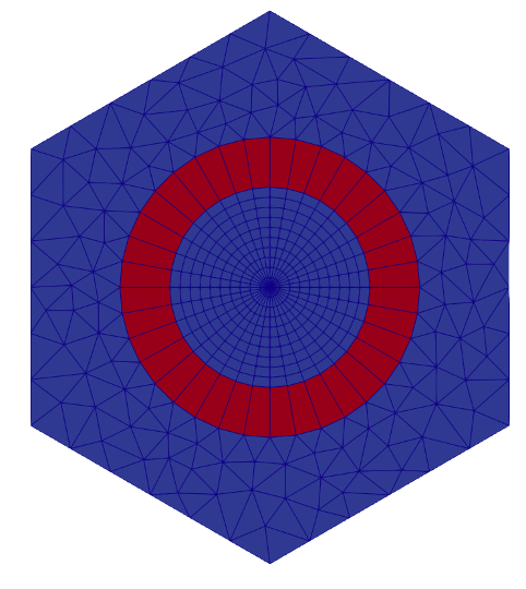
[Mesh<<<{"href": "../../../../syntax/Mesh/index.html"}>>>]
  [drum_pad]
    type = ControlDrumMeshGenerator<<<{"description": "This ControlDrumMeshGenerator object is designed to generate drum-like structures, with IDs, from a reactor geometry. These structures can be used directly within CoreMeshGenerator to stitchcontrol drums into a core lattice alongside AssemblyMeshGenerator structures", "href": "../../../../source/meshgenerators/ControlDrumMeshGenerator.html"}>>>
    reactor_params<<<{"description": "The ReactorMeshParams MeshGenerator that is the basis for this component mesh."}>>> = rmp
    assembly_type<<<{"description": "The assembly type integer ID to use for this control drum definition. This parameter should be uniquely defined for each ControlDrumMeshGenerator and AssemblyMeshGenerator structure in the RGMB workflow."}>>> = 4
    drum_inner_radius<<<{"description": "Inner radius of drum region"}>>> = 1.0
    drum_outer_radius<<<{"description": "Outer radius of drum region"}>>> = 1.5
    num_azimuthal_sectors<<<{"description": "Number of azimuthal sectors to sub-divide the drum region into"}>>> = 36
    drum_inner_intervals<<<{"description": "Number of radial mesh intervals in region up to inner drum radius"}>>> = 10

    pad_start_angle<<<{"description": "Starting angle of drum pad region"}>>> = 90
    pad_end_angle<<<{"description": "Ending angle of drum pad region"}>>> = 180
    region_ids<<<{"description": "IDs for each radial and axial zone for assignment of region_id extra element id. Inner indexing is radial zones (drum inner/drum/drum outer), outer indexing is axial"}>>> = '8 9 10 8'
  []
[]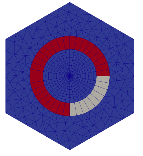
CoreMeshGenerator with ControlDrumMeshGenerator
Use of ControlDrumMeshGenerator allows for drum structures to be stitched directly into the lattice defined in CoreMeshGenerator. Use of flexible assembly stitching ensures that all assembly structures get stitched together without any hanging nodes.
[Mesh<<<{"href": "../../../../syntax/Mesh/index.html"}>>>]
  [rgmb_core]
    type = CoreMeshGenerator<<<{"description": "This CoreMeshGenerator object is designed to generate a core-like structure, with IDs, from a reactor geometry. The core-like structure consists of a pattern of assembly-like structures generated with AssemblyMeshGenerator and/or ControlDrumMeshGenerator and is permitted to have \"empty\" locations. The size and spacing of the assembly-like structures is defined, and enforced by declaration in the ReactorMeshParams.", "href": "../../../../source/meshgenerators/CoreMeshGenerator.html"}>>>
    inputs<<<{"description": "The AssemblyMeshGenerator and ControlDrumMeshGenerator objects that form the components of the assembly."}>>> = 'assembly1 drum_pad drum_nopad'
    dummy_assembly_name<<<{"description": "The place holder name in \"inputs\" that indicates an empty position."}>>> = empty
    pattern<<<{"description": "A double-indexed array starting with the upper-left corner where the indexrepresents the layout of input assemblies in the core lattice."}>>> = '2 1;
              1 0 2;
               2 1'
    extrude<<<{"description": "Determines if this is the final step in the geometry construction and extrudes the 2D geometry to 3D. If this is true then this mesh cannot be used in further mesh building in the Reactor workflow"}>>> = true
  []
[]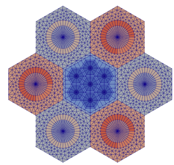
CoreMeshGenerator with Peripheral Ring
A core periphery region can be added utilizing either the PeripheralRingMeshGenerator or the PeripheralTriangleMeshGenerator.
[Mesh<<<{"href": "../../../../syntax/Mesh/index.html"}>>>]
  [rgmb_core]
    type = CoreMeshGenerator<<<{"description": "This CoreMeshGenerator object is designed to generate a core-like structure, with IDs, from a reactor geometry. The core-like structure consists of a pattern of assembly-like structures generated with AssemblyMeshGenerator and/or ControlDrumMeshGenerator and is permitted to have \"empty\" locations. The size and spacing of the assembly-like structures is defined, and enforced by declaration in the ReactorMeshParams.", "href": "../../../../source/meshgenerators/CoreMeshGenerator.html"}>>>
    inputs<<<{"description": "The AssemblyMeshGenerator and ControlDrumMeshGenerator objects that form the components of the assembly."}>>> = 'assembly1 assembly2 empty'
    dummy_assembly_name<<<{"description": "The place holder name in \"inputs\" that indicates an empty position."}>>> = empty
    pattern<<<{"description": "A double-indexed array starting with the upper-left corner where the indexrepresents the layout of input assemblies in the core lattice."}>>> = '2 1;
              1 0 2;
               2 1'
    extrude<<<{"description": "Determines if this is the final step in the geometry construction and extrudes the 2D geometry to 3D. If this is true then this mesh cannot be used in further mesh building in the Reactor workflow"}>>> = false

    mesh_periphery<<<{"description": "Determines if the core periphery should be meshed."}>>> = true
    periphery_generator<<<{"description": "The meshgenerator to use when meshing the core boundary."}>>> = triangle
    periphery_region_id<<<{"description": "ID for periphery zone for assignment of region_id extra element id."}>>> = 100
    outer_circle_radius<<<{"description": "Radius of outer circle boundary."}>>> = 8
    outer_circle_num_segments<<<{"description": "Number of radial segments to subdivide outer circle boundary."}>>> = 100
    desired_area<<<{"description": "Desired (maximum) triangle area, or 0 to skip uniform refinement"}>>> = 0.5
  []
[]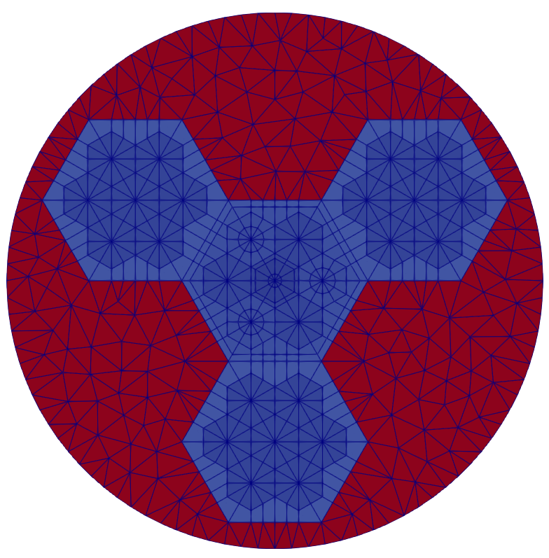
Default Block and External Boundary Names
An RGMB case can terminate at the pin, assembly, or core "level". Pins and assemblies always have a "type" assigned (a numeric integer specified as "pin_type" for pins and "assembly_type" for assemblies), whereas cores do not. The "level" and "type" are used in the naming schemes for the blocks and outer boundary as follows:
The default block names in the final mesh are
RGMB_(level)(type)andRGMB_(level)(type)_TRI(if triangular elements are present). For example,RGMB_PIN1andRMGB_PIN1_TRI, orRGMB_ASSEMBLY1andRGMB_ASSEMBLY1_TRI, orRGMB_COREandRGMB_CORE_TRI, for workflows ending at the pin, assembly or core level, respectively.The default outer boundary names in the radial dimension are
outer_(level)_(type). For example, for workflows ending at the pin, assembly or core level respectively, the outer boundary names areouter_pin_1,outer_assembly_1andouter_core.If the problem is extruded in the axial dimension, the
topandbottomboundaries also exist.For users that require a block name that is linked to the region ID of the element, ReactorMeshParams/"region_id_as_block_name" can be set to true to accomplish this. In this case, the block name will be set as
RGMB_(level)(type)_REG(region_id), where "region_id" refers to the region ID extra element integer the element. For triangular elements, the suffix "_TRI" will also be added.
RGMB Example: Heterogeneous to Homogeneous Conversion for Fast Reactor Core (ABTR)
Conversion of Heterogeneous to Homogeneous Sodium-Cooled Fast Reactor Core Mesh (ABTR)
This example illustrates the use of RGMB mesh generators to define a pin-resolved heterogeneous 3D hexagonal geometry core (ABTR (Shemon et al. (2015)), and using Griffin to convert this mesh to an equivalent homogenized core mesh with automatic geometry construction and region ID assignment. The final mesh constructed will be similar to the one presented earlier in this tutorial using base mesh generators.
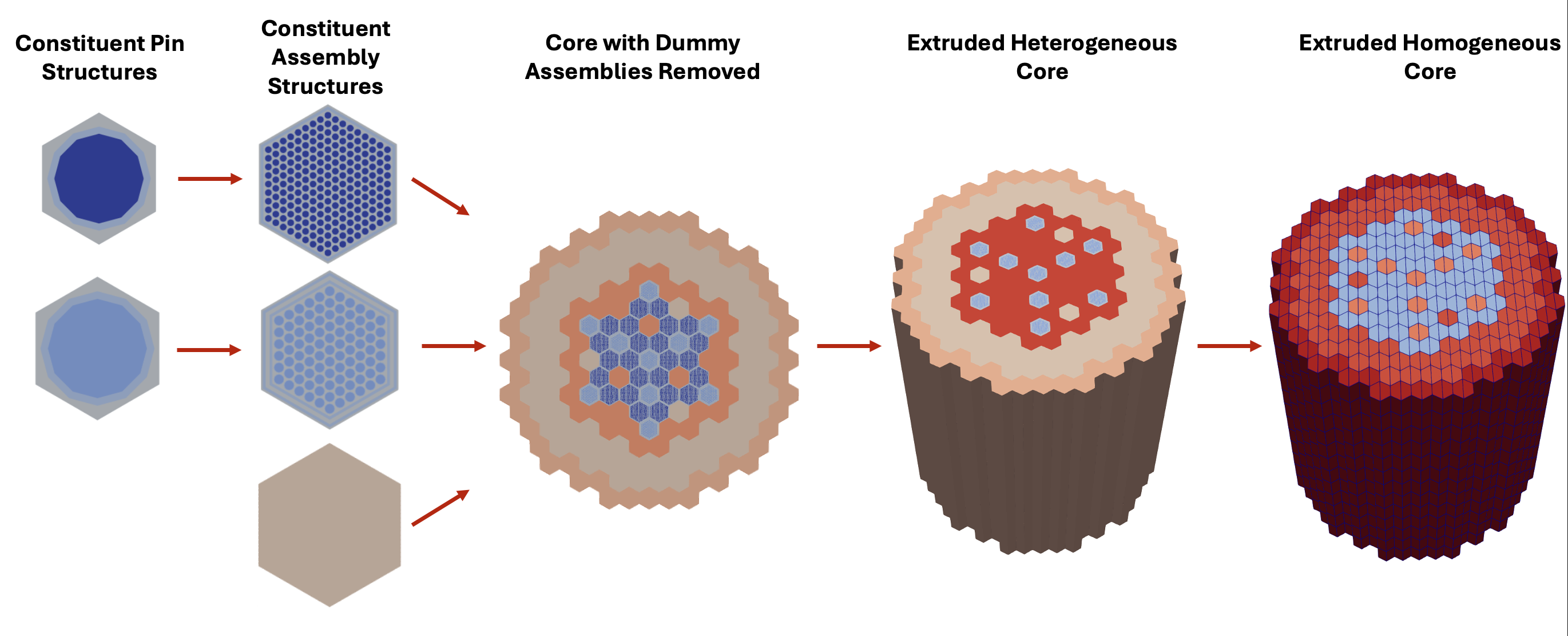
Hands-on package MOOSE input file (Heterogeneous ABTR mesh): input
Hands-on package Griffin input file (Equivalent homogeneous ABTR mesh, requires Griffin executable): input
ReactorMeshParams
ReactorMeshParams contains global mesh/geometry parameters including whether the final mesh is 2D or 3D, Cartesian or hexagonal, assembly pitch, and the axial discretization for the final extruded geometry. This information will be accessible to the other RGMB mesh generators and consistently used. Here we also invoke the option to enable flexible assembly stitching, so that dissimilar assembly structures can be stitched into the reactor core without any hanging nodes
[Mesh<<<{"href": "../../../../syntax/Mesh/index.html"}>>>]
  [rmp]
    type = ReactorMeshParams<<<{"description": "This ReactorMeshParams object acts as storage for persistent information about the reactor geometry.", "href": "../../../../source/meshgenerators/ReactorMeshParams.html"}>>>
    dim<<<{"description": "The dimension of the mesh to be generated"}>>> = 3 # Dimensionality of output mesh (2 or 3)
    geom<<<{"description": "The geometry type of the reactor mesh"}>>> = "Hex" # Geometry type (Hex or Square)
    assembly_pitch<<<{"description": "Center to center distance of assemblies"}>>> = ${assembly_pitch} # # Size of assembly flat-to-flat pitch

    axial_regions<<<{"description": "Length of each axial region"}>>> = '${dz_active_core_lower}
                     ${dz_active_core_upper}
                     ${dz_sodium_gp_upper}
                     ${dz_gp_upper}' # Size of each axial zone
    axial_mesh_intervals<<<{"description": "Number of elements in the Z direction for each axial region"}>>> = '${naxial_active_core_lower}
                            ${naxial_active_core_upper}
                            ${naxial_sodium_gp_upper}
                            ${naxial_gp_upper}' # Number of subintervals per axial zone
    top_boundary_id<<<{"description": "The boundary ID to set on top boundary of the extruded mesh"}>>> = 201 # Boundary ID assigned to top surface
    bottom_boundary_id<<<{"description": "The boundary ID to set on bottom boundary of the extruded mesh"}>>> = 202 # Boundary ID assigned to bottom surface
    radial_boundary_id<<<{"description": "The boundary ID to set on the outer radial boundary of a CoreMeshGenerator object"}>>> = 203 # Boundary ID assigned to radial surface
    flexible_assembly_stitching<<<{"description": "Use FlexiblePatternGenerator for stitching dissimilar assemblies together"}>>> = true # Set to true to stitch dissimilar assembly types together,
    # i.e. homogeneous and heterogeneous assemblies
  []
[]
Pin structures using PinMeshGenerator
PinMeshGenerator defines the constituent pin structures used for stitching into assemblies. The pin pitch, number of azimuthal sectors, and geometry / region ID information about each ring, background, and duct region are specified here.
PinMeshGenerator is called multiple times to define the various pin structures (3 fuel pin types and 1 control pin type).
[Mesh<<<{"href": "../../../../syntax/Mesh/index.html"}>>>]
  [fuel_pin_1]
    type = PinMeshGenerator<<<{"description": "This PinMeshGenerator object is designed to generate pin-like structures, with IDs, from a reactor geometry. Whether it be a square or hexagonal pin, they are divided into three substructures - the innermost radial pin regions, the single bridging background region, and the square or hexagonal ducts regions.", "href": "../../../../source/meshgenerators/PinMeshGenerator.html"}>>>
    reactor_params<<<{"description": "The ReactorMeshParams MeshGenerator that is the basis for this component conformal mesh."}>>> = rmp # Name of ReactorMeshParams object
    pin_type<<<{"description": "The integer ID for this pin type definition"}>>> = 1 # Unique identifier for pin type
    pitch<<<{"description": "The pitch for the outermost boundary polygon"}>>> = ${fuel_pin_pitch} # Pin pitch
    num_sectors<<<{"description": "Number of azimuthal sectors in each quadrant"}>>> = 2 # Number of azimuthal sectors per hexagonal side
    quad_center_elements<<<{"description": "Whether the center elements are quad or triangular."}>>> = false # Whether central mesh elements in inner ring should use
    # quad elements (true) or tri elements (false)
    ring_radii<<<{"description": "Radii of major concentric circles of the pin. If unspecified, no pin is present."}>>> = '${fuel_clad_r_i} ${fuel_clad_r_o}' # Radii for each ring
    mesh_intervals<<<{"description": "The number of meshing intervals for each region starting at the center. Parameter should be size:((length(ring_radii) + length(duct_halfpitch) + 1"}>>> = '1 1 1' # Number of radial intervals for each radial region
    # (inner ring, outer ring, background)
    region_ids<<<{"description": "IDs for each radial and axial zone for assignment of region_id extra element id. Inner indexing is radial zones (pin/background/duct), outer indexing is axial"}>>> = '${mid_lower_refl}     ${mid_lower_refl}     ${mid_lower_refl};
                  ${mid_fuel_1}         ${mid_ht9}            ${mid_sodium};
                  ${mid_upper_na_plen}  ${mid_upper_na_plen}  ${mid_upper_na_plen};
                  ${mid_upper_gas_plen} ${mid_upper_gas_plen} ${mid_upper_gas_plen}' # Region IDs for each radial region (inner ring, outer ring, background),
    # provided for each axial layer from bottom to top
  []
[]
Assembly structures using AssemblyMeshGenerator
AssemblyMeshGenerator takes the pin types previously defined and places them into a regular hexagonal grid. Additionally, coolant and duct regions need to be added around the pins in order to create the assembly geometry.
AssemblyMeshGenerator is called multiple times to define the various heterogeneous assemblies (3 fuel assemblies and 1 control assembly).
[Mesh<<<{"href": "../../../../syntax/Mesh/index.html"}>>>]
  [fuel_assembly_1]
    type = AssemblyMeshGenerator<<<{"description": "This AssemblyMeshGenerator object is designed to generate assembly-like structures, with IDs, from a reactor geometry. The assembly-like structures must consist of a full pattern of equal sized pins from PinMeshGenerator. A hexagonal assembly will be placed inside of a bounding hexagon consisting of a background region and, optionally, duct regions.", "href": "../../../../source/meshgenerators/AssemblyMeshGenerator.html"}>>>
    assembly_type<<<{"description": "The integer ID for this assembly type definition"}>>> = 1 # Unique identifier for pin type

    background_intervals<<<{"description": "Radial intervals in the assembly peripheral region."}>>> = 1 # Number of radial intervals in background region
    background_region_id<<<{"description": "The region id for the background area between the pins and the ducts to set region_id extra-element integer"}>>> = '${mid_lower_refl}
                            ${mid_sodium}
                            ${mid_upper_na_plen}
                            ${mid_upper_gas_plen}' # Region ID corresponding to background region,
    # defined for each axial layer from bottom to top
    duct_halfpitch<<<{"description": "Distance(s) from center to duct(s) inner boundaries."}>>> = '${fparse duct_pitch_inner / 2}
                      ${fparse duct_pitch_outer / 2}' # Halfpitches for assembly inner and outer duct regions
    duct_intervals<<<{"description": "Number of meshing intervals in each enclosing duct."}>>> = '1 1' # Number of radial intervals for each assembly duct region
    duct_region_ids<<<{"description": "The region id for the ducts from innermost to outermost, to set region_id extra-element integer."}>>> = ' ${mid_lower_refl}     ${mid_lower_refl};
                        ${mid_ht9}            ${mid_sodium};
                        ${mid_upper_na_plen}  ${mid_upper_na_plen};
                        ${mid_upper_gas_plen} ${mid_upper_gas_plen}' # Region IDs corresponding to inner and outer duct regions,
    # defined for each axial layer from bottom to top

    inputs<<<{"description": "The PinMeshGenerators that form the components of the assembly."}>>> = 'fuel_pin_1' # Name of contituent pin mesh structures
    pattern<<<{"description": "A double-indexed array starting with the upper-left corner where the indexrepresents the layout of input pins in the assembly lattice."}>>> = '0 0 0 0 0 0 0 0 0;
              0 0 0 0 0 0 0 0 0 0;
             0 0 0 0 0 0 0 0 0 0 0;
            0 0 0 0 0 0 0 0 0 0 0 0;
           0 0 0 0 0 0 0 0 0 0 0 0 0;
          0 0 0 0 0 0 0 0 0 0 0 0 0 0;
         0 0 0 0 0 0 0 0 0 0 0 0 0 0 0;
        0 0 0 0 0 0 0 0 0 0 0 0 0 0 0 0;
       0 0 0 0 0 0 0 0 0 0 0 0 0 0 0 0 0;
        0 0 0 0 0 0 0 0 0 0 0 0 0 0 0 0;
         0 0 0 0 0 0 0 0 0 0 0 0 0 0 0;
          0 0 0 0 0 0 0 0 0 0 0 0 0 0;
           0 0 0 0 0 0 0 0 0 0 0 0 0;
            0 0 0 0 0 0 0 0 0 0 0 0;
             0 0 0 0 0 0 0 0 0 0 0;
              0 0 0 0 0 0 0 0 0 0;
               0 0 0 0 0 0 0 0 0' # Lattice pattern of constituent pins
  []
[]
Homogeneous assembly structures using PinMeshGenerator
In order to define homogeneous assembly structures to stitch into the core, we use PinMeshGenerator once again (AssemblyMeshGenerator is only used for structures that consist of lattices of pins).
To define single assemblies directly with PinMeshGenerators for stitching with CoreMeshGenerator, PinMeshGenerator is used with "use_as_assembly" set to
true.In addition, "homogenized" =
trueis used to indicate that this region is homogenized.
[Mesh<<<{"href": "../../../../syntax/Mesh/index.html"}>>>]
  [reflector_assembly]
    type = PinMeshGenerator<<<{"description": "This PinMeshGenerator object is designed to generate pin-like structures, with IDs, from a reactor geometry. Whether it be a square or hexagonal pin, they are divided into three substructures - the innermost radial pin regions, the single bridging background region, and the square or hexagonal ducts regions.", "href": "../../../../source/meshgenerators/PinMeshGenerator.html"}>>>
    reactor_params<<<{"description": "The ReactorMeshParams MeshGenerator that is the basis for this component conformal mesh."}>>> = rmp # Name of ReactorMeshParams object
    pin_type<<<{"description": "The integer ID for this pin type definition"}>>> = 5 # Unique identiifier for assembly type
    pitch<<<{"description": "The pitch for the outermost boundary polygon"}>>> = ${assembly_pitch} # Assembly pitch
    homogenized<<<{"description": "Determines whether homogenized pin mesh should be generated"}>>> = true # Set to true to define homogenized mesh structure
    use_as_assembly<<<{"description": "Determines whether pin mesh should be used as an assembly mesh"}>>> = true # Set to true to treat output as assembly mesh structure, for stitching
    # directly into core lattice
    region_ids<<<{"description": "IDs for each radial and axial zone for assignment of region_id extra element id. Inner indexing is radial zones (pin/background/duct), outer indexing is axial"}>>> = '${mid_rad_refl};
                  ${mid_rad_refl};
                  ${mid_rad_refl};
                  ${mid_rad_refl}'
  []
[]
Heterogeneous core using CoreMeshGenerator
CoreMeshGenerator takes the input assemblies (heterogeneous and homogeneous) and stitches them into a core.
Since "flexible_assembly_stitching" =
truein ReactorMeshParams, the different assembly types are stitched together without hanging nodes.Dummy assemblies do not need to be defined explicitly and instead can be referenced in the core lattice input by specifying a name in "dummy_assembly_name".
This is the last step you can run if you do not have Griffin executable access.
[Mesh<<<{"href": "../../../../syntax/Mesh/index.html"}>>>]
  [het_core]
    type = CoreMeshGenerator<<<{"description": "This CoreMeshGenerator object is designed to generate a core-like structure, with IDs, from a reactor geometry. The core-like structure consists of a pattern of assembly-like structures generated with AssemblyMeshGenerator and/or ControlDrumMeshGenerator and is permitted to have \"empty\" locations. The size and spacing of the assembly-like structures is defined, and enforced by declaration in the ReactorMeshParams.", "href": "../../../../source/meshgenerators/CoreMeshGenerator.html"}>>>
    inputs<<<{"description": "The AssemblyMeshGenerator and ControlDrumMeshGenerator objects that form the components of the assembly."}>>> = 'fuel_assembly_1 fuel_assembly_2
              fuel_assembly_3 control_assembly
              reflector_assembly shielding_assembly
              dummy' # Name of constituent assemblies
    dummy_assembly_name<<<{"description": "The place holder name in \"inputs\" that indicates an empty position."}>>> = 'dummy' # Name of dummy assembly to
    # remove from core lattice pattern
    pattern<<<{"description": "A double-indexed array starting with the upper-left corner where the indexrepresents the layout of input assemblies in the core lattice."}>>> = '6 6 5 5 5 5 5 6 6;
              6 5 5 4 4 4 4 5 5 6;
             5 5 4 4 4 4 4 4 4 5 5;
            5 4 4 4 4 1 1 4 4 4 4 5;
           5 4 4 4 1 1 3 1 1 4 4 4 5;
          5 4 4 1 1 2 0 0 4 1 1 4 4 5;
         5 4 4 1 3 0 0 2 0 0 3 1 4 4 5;
        6 5 4 4 1 0 3 0 0 3 0 1 4 4 5 6;
       6 5 4 4 1 4 0 0 3 0 0 2 1 4 4 5 6;
        6 5 4 4 1 0 2 0 0 2 0 1 4 4 5 6;
         5 4 4 1 3 0 0 3 0 0 3 1 4 4 5;
          5 4 4 1 1 2 0 0 4 1 1 4 4 5;
           5 4 4 4 1 1 3 1 1 4 4 4 5;
            5 4 4 4 4 1 1 4 4 4 4 5;
             5 5 4 4 4 4 4 4 4 5 5;
              6 5 5 4 4 4 4 5 5 6;
               6 6 5 5 5 5 5 6 6' # Lattice pattern of constituent assemblies
    extrude<<<{"description": "Determines if this is the final step in the geometry construction and extrudes the 2D geometry to 3D. If this is true then this mesh cannot be used in further mesh building in the Reactor workflow"}>>> = true # Extrude core to 3-D
  []
[]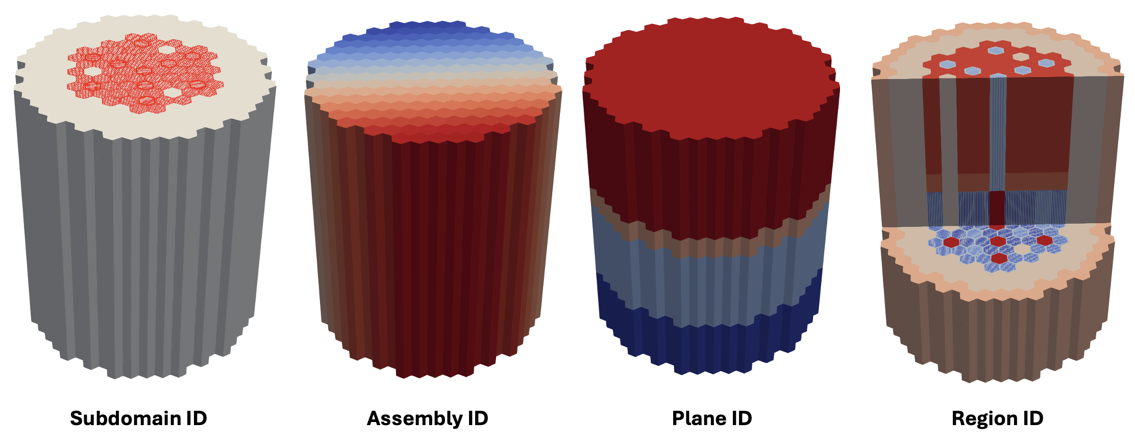
Equivalent homogeneous core using Griffin's EquivalentCoreMeshGenerator
EquivalentCoreMeshGenerator is a mesh generator defined in Griffin that converts an input heterogeneous RGMB mesh into equivalent "duct heterogeneous", "ring heterogeneous", or "fully homogeneous" representations. Each unique subassembly region (radial + axial location) will have its own region ID in the equivalent core mesh. This step requires Griffin executable access.
In this case, EquivalentCoreMeshGenerator will determine uniqueness based on both the geometry AND region ID mapping of each subassembly region in the heterogeneous core.
[Mesh<<<{"href": "../../../../syntax/Mesh/index.html"}>>>]
  [hom_core]
    type = EquivalentCoreMeshGenerator
    input = het_core # Name of input heterogeneous mesh
    target_geometry = full_hom # Target geometry type for
    # equivalent core mesh generation
    # (options are full_hom, duct_het, and ring_het)
    quad_center_elements = true # Whether output homogeneous should
    # be defined using quad elements (true)
    # or tri elements (false)
  []
[]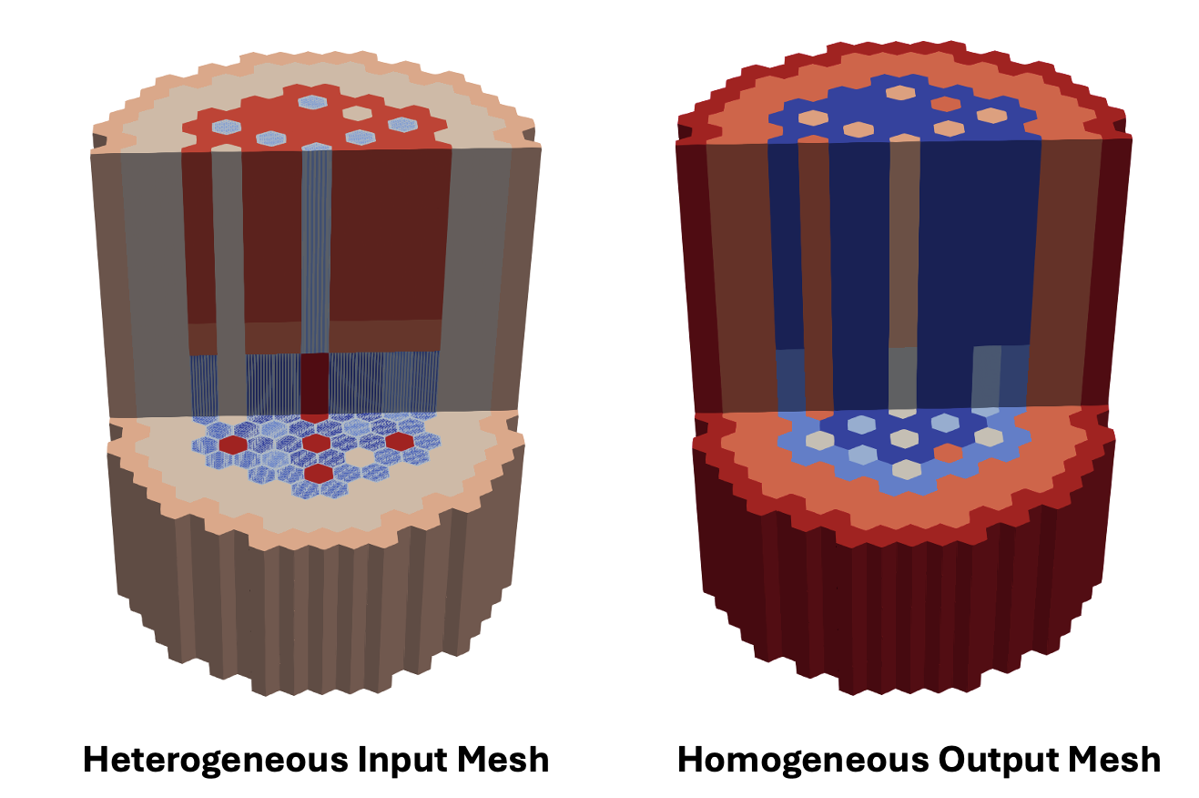
Use of EquivalentCoreMeshGenerator with Griffin
EquivalentCoreMeshGenerator will define the same reporting IDs used by RGMB.
In addition, EquivalentCoreMeshGenerator will automatically copy the "region_id" reporting ID to the "material_id" reporting ID, since Griffin recognizes material ID assignments through the material_id tag.
Material definition in the Griffin input file is then greatly simplified since material_id is defined directly on mesh. No additional mapping is needed.
[Materials<<<{"href": "../../../../syntax/Materials/index.html"}>>>]
  [matid]
    type = MixedMatIDNeutronicsMaterial
    block = 'RGMB_CORE'
    isotopes = 'pseudo'
  []
[]
EquivalentCoreMeshGenerator and RGMB label outer boundary sidesets for core structures with pre-defined names – "top" for top boundary, "bottom" for bottom boundary, and "outer_core" for radial boundary. Boundary conditions are assigned to these sidesets in Griffin.
[TransportSystems]
  particle = neutron
  G = 33
  VacuumBoundary = 'outer_core top bottom'
  equation_type = eigenvalue
  [sn]
    scheme = DFEM-SN
    family = L2_LAGRANGE
    order = FIRST
    AQtype = Gauss-Chebyshev
    NPolar = 2
    NAzmthl = 3
    NA = 1
  []
[]
RGMB Example: 2-D Empire Microreactor Core Mesh with Control Drum Stitching
2-D Empire Microreactor Core with Control Drum Stitching
This example illustrates the use of RGMB mesh generators to define a heterogeneous 2D hexagonal microreactor core with control drum structures for the EMPIRE problem (Matthews et al. (2021)). The primary focus of this tutorial is to familiarize users with ControlDrumMeshGenerator to create control drum structures for stitching into the core lattice.
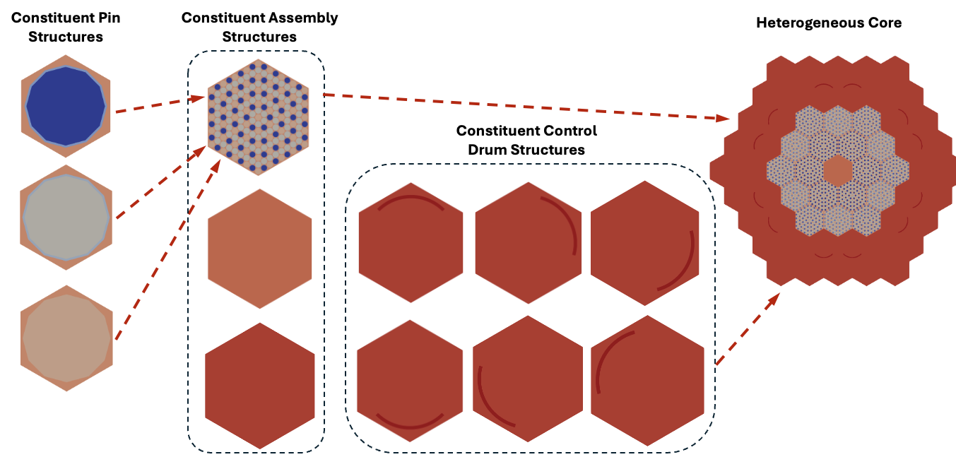
Hands-on package MOOSE input file (Heterogeneous EMPIRE mesh): tutorials/tutorial04_meshing/doc/listings/reactor_examples/rgmb_empire/rgmb_empire.i
ReactorMeshParams
ReactorMeshParams contains global mesh/geometry parameters including whether the final mesh is 2D or 3D, Cartesian or hexagonal, assembly pitch, and the axial discretization for the final extruded geometry. Here we also invoke the option to enable flexible assembly stitching with "flexible_assembly_stitching", so that dissimilar assembly structures can be stitched into the reactor core without any hanging nodes. This parameter needs to be set to true in order to use ControlDrumMeshGenerator.
[Mesh<<<{"href": "../../../../syntax/Mesh/index.html"}>>>]
  [rmp]
    type = ReactorMeshParams<<<{"description": "This ReactorMeshParams object acts as storage for persistent information about the reactor geometry.", "href": "../../../../source/meshgenerators/ReactorMeshParams.html"}>>>
    dim<<<{"description": "The dimension of the mesh to be generated"}>>> = 2 # Dimensionality of output mesh (2 or 3)
    geom<<<{"description": "The geometry type of the reactor mesh"}>>> = "Hex" # Geometry type (Hex or Square)
    assembly_pitch<<<{"description": "Center to center distance of assemblies"}>>> = 32.353 # Size of assembly flat-to-flat pitch
    radial_boundary_id<<<{"description": "The boundary ID to set on the outer radial boundary of a CoreMeshGenerator object"}>>> = 203 # Boundary id assigned to radial surface
    flexible_assembly_stitching<<<{"description": "Use FlexiblePatternGenerator for stitching dissimilar assemblies together"}>>> = true # Set to true to stitch dissimilar assembly types together,
    # i.e. homogeneous, heterogeneous, and control drum assemblies
    region_id_as_block_name<<<{"description": "Set block names based on region id"}>>> = true # Set this to true to assign block name based on the region ID
    # of the region. If quad and tri elements share the same region ID
    # two separate block names will be created
  []
[]
Pin structures using PinMeshGenerator
The EMPIRE core features heterogeneous fuel assemblies, homogeneous air and reflector regions, and control drum structures all stitched into a hexagonal core lattice. We begin with defining the heterogeneous fuel assemblies.
PinMeshGenerator defines the constituent pin structures used for stitching into assemblies. The pin pitch, number of azimuthal sectors, and geometry / region ID information about each ring, background, and duct region are specified here.
PinMeshGenerator is called multiple times to define the various pin structures (3 fuel pin types, 1 heat pipe pintype, and 1 moderator pin type).
[Mesh<<<{"href": "../../../../syntax/Mesh/index.html"}>>>]
  [fuel_pin_1]
    type = PinMeshGenerator<<<{"description": "This PinMeshGenerator object is designed to generate pin-like structures, with IDs, from a reactor geometry. Whether it be a square or hexagonal pin, they are divided into three substructures - the innermost radial pin regions, the single bridging background region, and the square or hexagonal ducts regions.", "href": "../../../../source/meshgenerators/PinMeshGenerator.html"}>>>
    reactor_params<<<{"description": "The ReactorMeshParams MeshGenerator that is the basis for this component conformal mesh."}>>> = rmp # Name of ReactorMeshParams object
    pin_type<<<{"description": "The integer ID for this pin type definition"}>>> = 1 # Unique identifier for pin type
    pitch<<<{"description": "The pitch for the outermost boundary polygon"}>>> = 2.15 # Pin pitch
    num_sectors<<<{"description": "Number of azimuthal sectors in each quadrant"}>>> = 2 # Number of azimuthal sectors per hexagonal side
    quad_center_elements<<<{"description": "Whether the center elements are quad or triangular."}>>> = false # Whether central mesh elements in inner ring should use
    # quad elements (true) or tri elements (false)
    ring_radii<<<{"description": "Radii of major concentric circles of the pin. If unspecified, no pin is present."}>>> = '0.925 0.975' # Radii for each ring
    mesh_intervals<<<{"description": "The number of meshing intervals for each region starting at the center. Parameter should be size:((length(ring_radii) + length(duct_halfpitch) + 1"}>>> = '3 1 1' # Number of radial intervals for each radial region
    # (inner ring, outer ring, background)
    region_ids<<<{"description": "IDs for each radial and axial zone for assignment of region_id extra element id. Inner indexing is radial zones (pin/background/duct), outer indexing is axial"}>>> = '${mid_fuel_1} ${mid_fgap} ${mid_ss}' # Region IDs for each radial region
    # (inner ring, outer ring, background)
  []
[]
Assembly structures using AssemblyMeshGenerator
AssemblyMeshGenerator takes the pin types previously defined and places them into a regular hexagonal grid. Additionally, a stainless steel background region is added around the pins in order to create the assembly geometry.
AssemblyMeshGenerator is called multiple times to define the various heterogeneous assemblies (3 fuel assemblies).
[Mesh<<<{"href": "../../../../syntax/Mesh/index.html"}>>>]
  [fuel_assembly_1]
    type = AssemblyMeshGenerator<<<{"description": "This AssemblyMeshGenerator object is designed to generate assembly-like structures, with IDs, from a reactor geometry. The assembly-like structures must consist of a full pattern of equal sized pins from PinMeshGenerator. A hexagonal assembly will be placed inside of a bounding hexagon consisting of a background region and, optionally, duct regions.", "href": "../../../../source/meshgenerators/AssemblyMeshGenerator.html"}>>>
    assembly_type<<<{"description": "The integer ID for this assembly type definition"}>>> = 1 # Unique identifier for pin type
    background_intervals<<<{"description": "Radial intervals in the assembly peripheral region."}>>> = 1 # Number of radial intervals in background region
    background_region_id<<<{"description": "The region id for the background area between the pins and the ducts to set region_id extra-element integer"}>>> = '${mid_ss}' # Region ID corresponding to background region
    inputs<<<{"description": "The PinMeshGenerators that form the components of the assembly."}>>> = 'fuel_pin_1 hpipe_pin mod_pin' # Name of contituent pin mesh structures
    pattern<<<{"description": "A double-indexed array starting with the upper-left corner where the indexrepresents the layout of input pins in the assembly lattice."}>>> = '1 0 1 0 1 0 1 0 1;
              0 2 2 2 2 2 2 2 2 0;
             1 2 1 0 1 0 1 0 1 2 1;
            0 2 0 2 2 2 2 2 2 0 2 0;
           1 2 1 2 1 0 1 0 1 2 1 2 1;
          0 2 0 2 0 2 2 2 2 0 2 0 2 0;
         1 2 1 2 1 2 1 0 1 2 1 2 1 2 1;
        0 2 0 2 0 2 0 2 2 0 2 0 2 0 2 0;
       1 2 1 2 1 2 1 2 1 2 1 2 1 2 1 2 1;
        0 2 0 2 0 2 0 2 2 0 2 0 2 0 2 0;
         1 2 1 2 1 2 1 0 1 2 1 2 1 2 1;
          0 2 0 2 0 2 2 2 2 0 2 0 2 0;
           1 2 1 2 1 0 1 0 1 2 1 2 1;
            0 2 0 2 2 2 2 2 2 0 2 0;
             1 2 1 0 1 0 1 0 1 2 1;
              0 2 2 2 2 2 2 2 2 0;
               1 0 1 0 1 0 1 0 1' # Lattice pattern of constituent pins
  []
[]
Homogeneous assembly structures using PinMeshGenerator
In order to define homogeneous assembly structures to stitch into the core, we use PinMeshGenerator once again (AssemblyMeshGenerator is only used for structures that consist of lattices of pins).
To define single assemblies directly with PinMeshGenerators for stitching with CoreMeshGenerator, PinMeshGenerator is used with "use_as_assembly" set to
true. In addition, "homogenized" =trueis used to indicate that this region is homogenized.
[Mesh<<<{"href": "../../../../syntax/Mesh/index.html"}>>>]
  [refl_assembly]
    type = PinMeshGenerator<<<{"description": "This PinMeshGenerator object is designed to generate pin-like structures, with IDs, from a reactor geometry. Whether it be a square or hexagonal pin, they are divided into three substructures - the innermost radial pin regions, the single bridging background region, and the square or hexagonal ducts regions.", "href": "../../../../source/meshgenerators/PinMeshGenerator.html"}>>>
    reactor_params<<<{"description": "The ReactorMeshParams MeshGenerator that is the basis for this component conformal mesh."}>>> = rmp
    pin_type<<<{"description": "The integer ID for this pin type definition"}>>> = 5
    pitch<<<{"description": "The pitch for the outermost boundary polygon"}>>> = 32.353
    region_ids<<<{"description": "IDs for each radial and axial zone for assignment of region_id extra element id. Inner indexing is radial zones (pin/background/duct), outer indexing is axial"}>>> = '${mid_reflector}'
    homogenized<<<{"description": "Determines whether homogenized pin mesh should be generated"}>>> = true
    use_as_assembly<<<{"description": "Determines whether pin mesh should be used as an assembly mesh"}>>> = true
  []
[]
Control drum structures using ControlDrumMeshGenerator
In order to define control drum structures to stitch into the core, we use ControlDrumMeshGenerator. This process is repeated for each of the 6 unique drum orientations that are part of the core lattice.
"drum_inner_radius" and "drum_outer_radius" control the inner and outer radius of the drum region, while "drum_inner_intervals" and "drum_intervals" control the radial mesh density of the drum inner and drum regions respectively.
"num_azimuthal_sectors" controls the azimuthal mesh density of the control drum structure.
Additional parameters are provided to ControlDrumMeshGenerator to create explicit drum pad regions. "pad_start_angle" and "pad_end_angle" set the start and end angles of the drum pad region.
The "region_ids" parameter takes four values per axial layer, representing the four radial regions of the control drum structure (drum inner, drum pad, drum ex-pad, background)
[Mesh<<<{"href": "../../../../syntax/Mesh/index.html"}>>>]
  [cd_ne]
    type = ControlDrumMeshGenerator<<<{"description": "This ControlDrumMeshGenerator object is designed to generate drum-like structures, with IDs, from a reactor geometry. These structures can be used directly within CoreMeshGenerator to stitchcontrol drums into a core lattice alongside AssemblyMeshGenerator structures", "href": "../../../../source/meshgenerators/ControlDrumMeshGenerator.html"}>>>
    assembly_type<<<{"description": "The assembly type integer ID to use for this control drum definition. This parameter should be uniquely defined for each ControlDrumMeshGenerator and AssemblyMeshGenerator structure in the RGMB workflow."}>>> = 6 # Unique identifier for assembly type
    reactor_params<<<{"description": "The ReactorMeshParams MeshGenerator that is the basis for this component mesh."}>>> = rmp # Name of ReactorMeshParams object
    drum_inner_radius<<<{"description": "Inner radius of drum region"}>>> = 13.8 # Inner radius of drum region
    drum_outer_radius<<<{"description": "Outer radius of drum region"}>>> = 14.8 # Outer radius of drum region
    num_azimuthal_sectors<<<{"description": "Number of azimuthal sectors to sub-divide the drum region into"}>>> = 72 # Number of azimuthal sectors for
    drum_inner_intervals<<<{"description": "Number of radial mesh intervals in region up to inner drum radius"}>>> = 15 # Number of radial intervals in drum inner region
    drum_intervals<<<{"description": "Number of radial mesh intervals in drum region"}>>> = 3 # Number of radial intervals in drum region
    pad_start_angle<<<{"description": "Starting angle of drum pad region"}>>> = 15 # Starting angle of drum pad region
    pad_end_angle<<<{"description": "Ending angle of drum pad region"}>>> = 105 # Ending angle of drum pad region
    region_ids<<<{"description": "IDs for each radial and axial zone for assignment of region_id extra element id. Inner indexing is radial zones (drum inner/drum/drum outer), outer indexing is axial"}>>> = '${mid_reflector} ${mid_drum_pad}
                  ${mid_reflector} ${mid_reflector}' # Region IDs of control drum region
    # (drum inner, drum pad, drum ex-pad, background)
  []
[]
Heterogeneous core using CoreMeshGenerator
CoreMeshGenerator takes the input assemblies (heterogeneous and homogeneous) and drum structures and stitches them into a core.
Since "flexible_assembly_stitching" =
truein ReactorMeshParams, the different assembly types are stitched together without hanging nodes.
[Mesh<<<{"href": "../../../../syntax/Mesh/index.html"}>>>]
  [core]
    type = CoreMeshGenerator<<<{"description": "This CoreMeshGenerator object is designed to generate a core-like structure, with IDs, from a reactor geometry. The core-like structure consists of a pattern of assembly-like structures generated with AssemblyMeshGenerator and/or ControlDrumMeshGenerator and is permitted to have \"empty\" locations. The size and spacing of the assembly-like structures is defined, and enforced by declaration in the ReactorMeshParams.", "href": "../../../../source/meshgenerators/CoreMeshGenerator.html"}>>>
    inputs<<<{"description": "The AssemblyMeshGenerator and ControlDrumMeshGenerator objects that form the components of the assembly."}>>> = 'fuel_assembly_1 fuel_assembly_2
              fuel_assembly_3 airhole_assembly
              refl_assembly cd_ne cd_se cd_s cd_sw
              cd_nw cd_n' # Name of constituent assemblies
    pattern<<<{"description": "A double-indexed array starting with the upper-left corner where the indexrepresents the layout of input assemblies in the core lattice."}>>> = '4  4  4  4  4;
              4  4 10 10  4  4;
             4  9  1  2  1  5  4;
            4  9  2  0  0  2  5  4;
           4  4  1  0  3  0  1  4  4;
            4  8  2  0  0  2  6  4;
             4  8  1  2  1  6  4;
              4  4  7  7  4  4;
               4  4  4  4  4' # Lattice pattern of constituent assemblies

    # Define depletion IDs for each unique (pin, region_id) pair
    generate_depletion_id<<<{"description": "Determine wheter the depletion ID is assigned."}>>> = true
    depletion_id_type<<<{"description": "Determine level of details in depletion ID assignment."}>>> = pin
  []
[]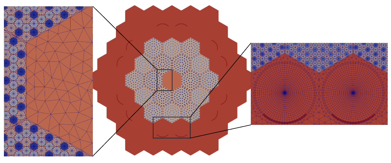
Use of RGMB Mesh with Griffin
Griffin recognizes material ID assignments through the material_id tag. Therefore, the region_id tags need to be renamed to material_id. This is done using ExtraElementIDCopyGenerator.
[Mesh<<<{"href": "../../../../syntax/Mesh/index.html"}>>>]
  [empire_mesh]
    type = ExtraElementIDCopyGenerator<<<{"description": "Copy an extra element ID to other extra element IDs.", "href": "../../../../source/meshgenerators/ExtraElementIDCopyGenerator.html"}>>>
    input<<<{"description": "The mesh we want to modify"}>>> = core
    source_extra_element_id<<<{"description": "The extra element ID to be copied"}>>> = region_id
    target_extra_element_ids<<<{"description": "The target extra element IDs"}>>> = 'material_id'
  []
[]
Material definition in the Griffin input file is then greatly simplified since material_id is defined directly on mesh. No additional mapping is needed.
[Materials<<<{"href": "../../../../syntax/Materials/index.html"}>>>]
  [matid]
    type = MixedMatIDNeutronicsMaterial
    block = 'RGMB_CORE RGMB_CORE_TRI'
    isotopes = 'pseudo'
  []
[]
RGMB labels outer boundary sidesets with pre-defined names – "top" for top boundary, "bottom" for bottom boundary, and "outer_core" for radial boundary. Boundary conditions are assigned to these sidesets in Griffin. Since this is a 2-D mesh, only the "outer_core" boundary sideset is created by RGMB.
[TransportSystems]
  particle = neutron
  G = 6
  VacuumBoundary = 'outer_core'
  equation_type = eigenvalue
  [sn]
    scheme = DFEM-SN
    family = L2_LAGRANGE
    order = FIRST
    AQtype = Gauss-Chebyshev
    NPolar = 2
    NAzmthl = 3
    NA = 1
  []
[]
Advanced Meshing Tools
Quadratic Element Capabilities
Quadratic elements meshing is available for all MOOSE Reactor Module meshing tools commonly used for reactor meshing. The quadratic element options can be selected by setting tri_element_type as TRI6 or TRI7, and quad_element_type as QUAD8 or QUAD9 in the 2D mesh generators. The 2D-to-3D mesh generators such as AdvancedExtruderGenerator detect 2D quadratic elements and create 3D quadratic elements accordingly.
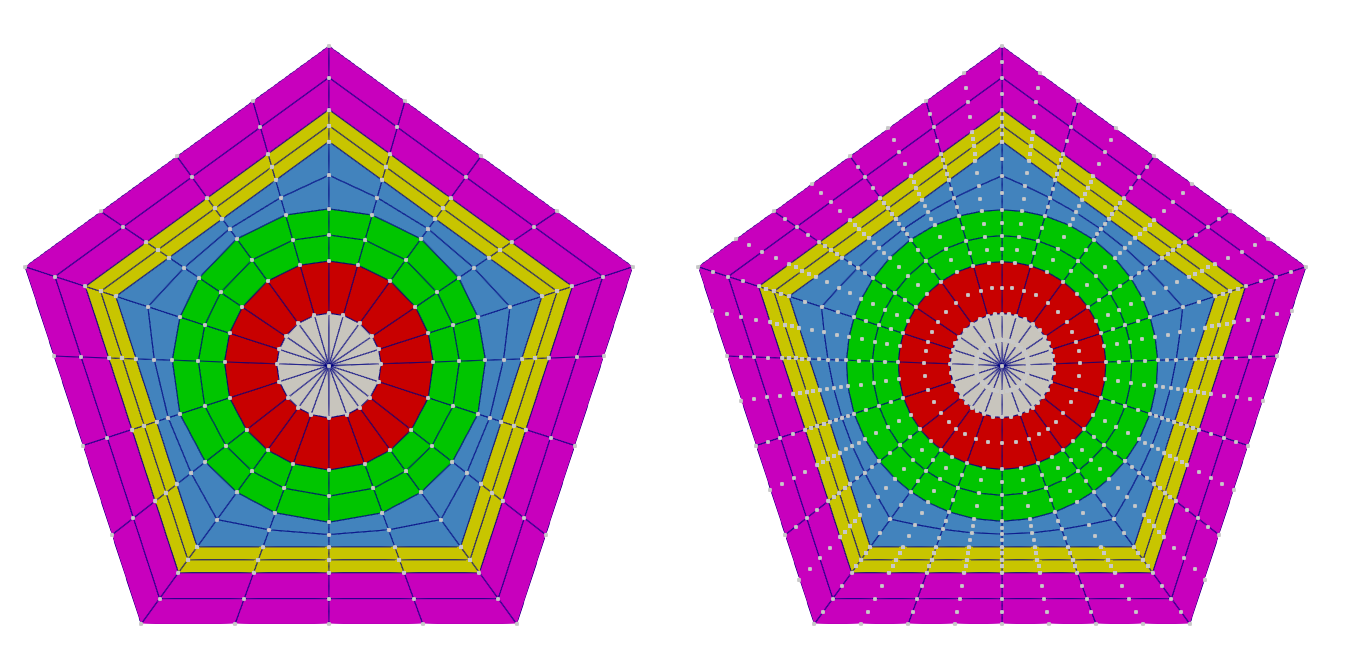
ParsedCurveGenerator
The ParsedCurveGenerator object generates a 3D curve mesh composed of EDGE2 elements which connect the series of points given by , , . This is useful when the user wants to construct a non-standard boundary and mesh inside of it.
[Mesh<<<{"href": "../../../../syntax/Mesh/index.html"}>>>]
  [pcg]
    type = ParsedCurveGenerator<<<{"description": "This ParsedCurveGenerator object is designed to generate a mesh of a curve that consists of EDGE2, EDGE3, or EDGE4 elements.", "href": "../../../../source/meshgenerators/ParsedCurveGenerator.html"}>>>
    x_formula<<<{"description": "Function expression of x(t)"}>>> = 'cos(t)'
    y_formula<<<{"description": "Function expression of y(t)"}>>> = 'sin(t)'
    z_formula<<<{"description": "Function expression of z(t)"}>>> = 't'
    section_bounding_t_values<<<{"description": "The 't' values that bound the sections of the curve. Start and end points must be included. The number of entries in 'nums_segments' should be equal to one less than the number of entries in this parameter."}>>> = '0 ${fparse 4*pi}'
    nums_segments<<<{"description": "Numbers of segments (EDGE elements) of each section of the curve to be generated. The number of entries in this parameter should be equal to one less than the number of entries in 'section_bounding_t_values'"}>>> = 24
  []
[]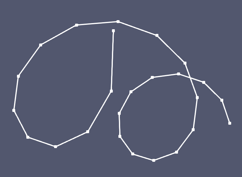
FillBetweenCurvesGenerator, FillBetweenPointVectorsGenerator, and FillBetweenSidesetsGenerator
Several mesh generators are available to the user to generate a "transition layer" between two curves using linear triangle elements (TRI3). Behind the scenes, these mesh generators use MOOSE's FillBetweenPointVectorsTools capability to generate a "transition layer" between two given curves (in the form of two vectors of points).
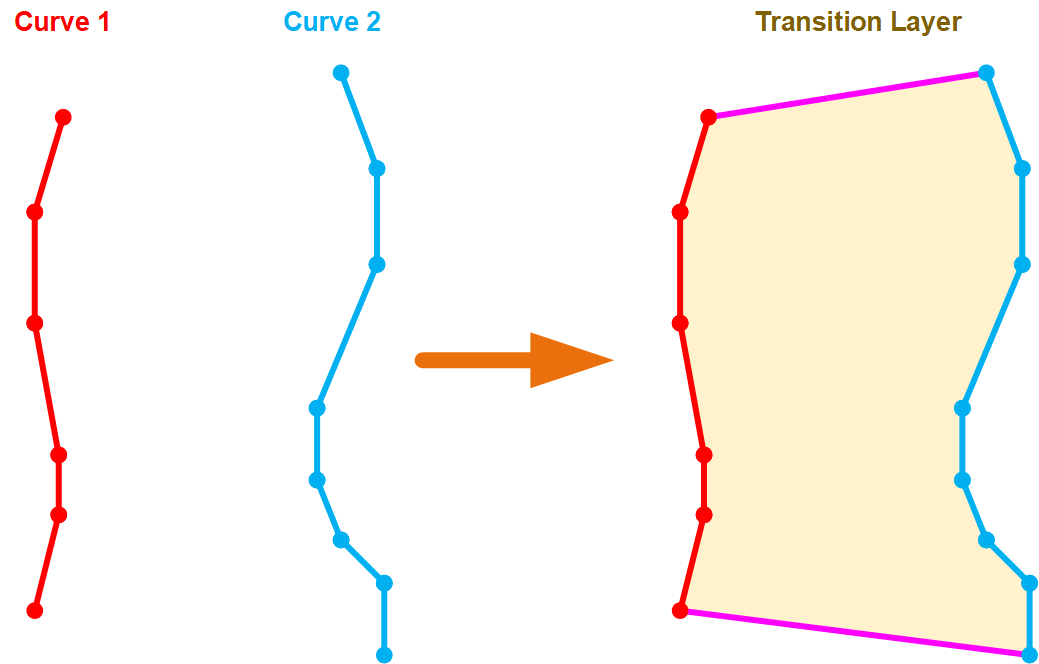
FillBetweenCurvesGenerator
The FillBetweenCurvesGenerator object is designed to generate a transition layer to connect two boundaries of two input meshes. The user provides two 1D meshes (curves) which should be connected to each other with transition layers.
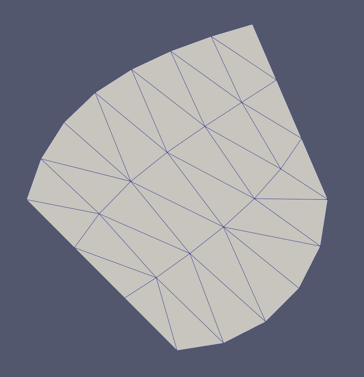
FillBetweenSidesetsGenerator
The FillBetweenSidesetsGenerator object is designed to generate a transition layer to connect two boundaries of two input meshes. The user provides two 2D input meshes with sidesets. These sidesets specify which boundaries of each mesh should be connected to the other mesh with a transitional layer.
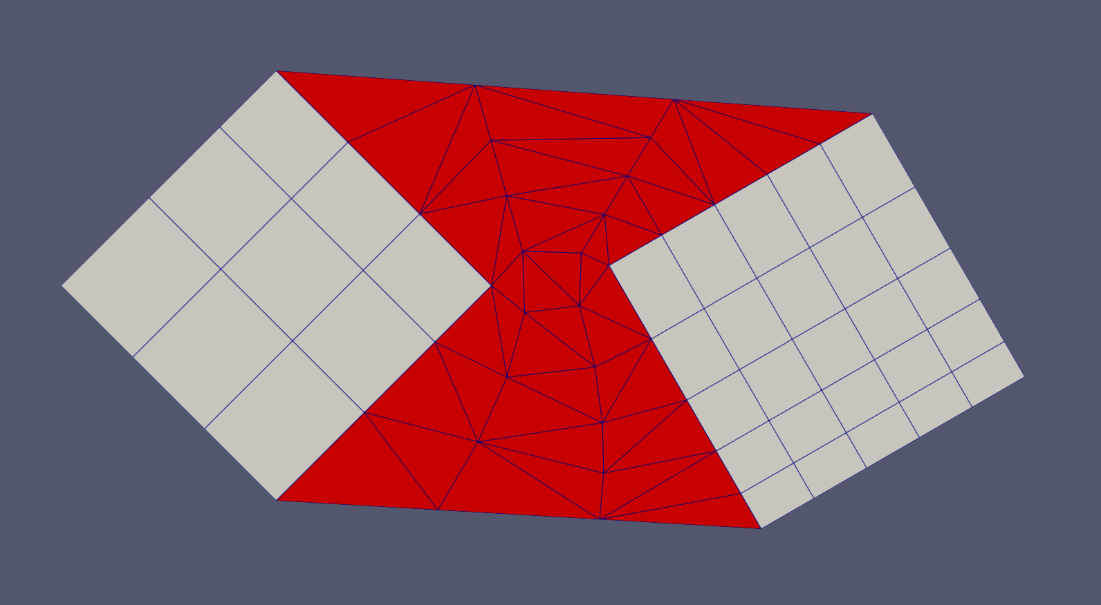
FillBetweenPointVectorsGenerator
This FillBetweenPointVectorsGenerator object generates a transition layer between two point vectors with different numbers of nodes. The user should provide two vectors of points as well as the number of layers of elements to create between the two vectors.
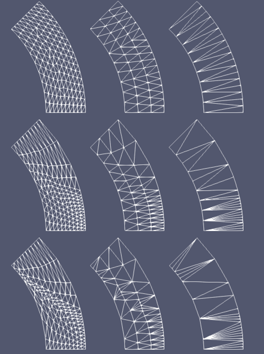
XYDelaunayGenerator
XYDelaunayGenerator creates an unstructured mesh consisting of TRI3 elements based on a given external boundary and, optionally, a series of internal hole meshes.
XYDelaunayGenerator is extremely powerful when combined with ParsedCurveGenerator and other Reactor module objects already described, as it can mesh very irregularly shaped regions.
[Mesh<<<{"href": "../../../../syntax/Mesh/index.html"}>>>]
  [outer_bdy]
    type = PolyLineMeshGenerator<<<{"description": "Generates meshes from edges connecting a list of points.", "href": "../../../../source/meshgenerators/PolyLineMeshGenerator.html"}>>>
    points<<<{"description": "The points defining the polyline, in order"}>>> = '-1.0 0.0 0.0
              0.0 -1.0 0.0
              1.0 0.0 0.0
              0.0 2.0 0.0'
    loop<<<{"description": "Whether edges should form a closed loop"}>>> = true
  []
  [hole_1]
    type = PolyLineMeshGenerator<<<{"description": "Generates meshes from edges connecting a list of points.", "href": "../../../../source/meshgenerators/PolyLineMeshGenerator.html"}>>>
    points<<<{"description": "The points defining the polyline, in order"}>>> = '-0.5 -0.1 0.0
              -0.3 -0.1 0.0
              -0.3 0.1 0.0
              -0.5 0.1 0.0'
    loop<<<{"description": "Whether edges should form a closed loop"}>>> = true
  []
  [hole_2]
    type = PolyLineMeshGenerator<<<{"description": "Generates meshes from edges connecting a list of points.", "href": "../../../../source/meshgenerators/PolyLineMeshGenerator.html"}>>>
    points<<<{"description": "The points defining the polyline, in order"}>>> = '0.3 -0.1 0.0
              0.5 -0.1 0.0
              0.5 0.1 0.0
              0.3 0.1 0.0'
    loop<<<{"description": "Whether edges should form a closed loop"}>>> = true
  []
  [triang]
    type = XYDelaunayGenerator<<<{"description": "Triangulates meshes within boundaries defined by input meshes.", "href": "../../../../source/meshgenerators/XYDelaunayGenerator.html"}>>>
    boundary<<<{"description": "The input MeshGenerator defining the output outer boundary and required Steiner points."}>>> = 'outer_bdy'
    holes<<<{"description": "The MeshGenerators that define mesh holes."}>>> = 'hole_1
             hole_2'
    add_nodes_per_boundary_segment<<<{"description": "How many more nodes to add in each outer boundary segment."}>>> = 3
    refine_boundary<<<{"description": "Whether to allow automatically refining the outer boundary."}>>> = false
    desired_area<<<{"description": "Desired (maximum) triangle area, or 0 to skip uniform refinement"}>>> = 0.05
  []
[]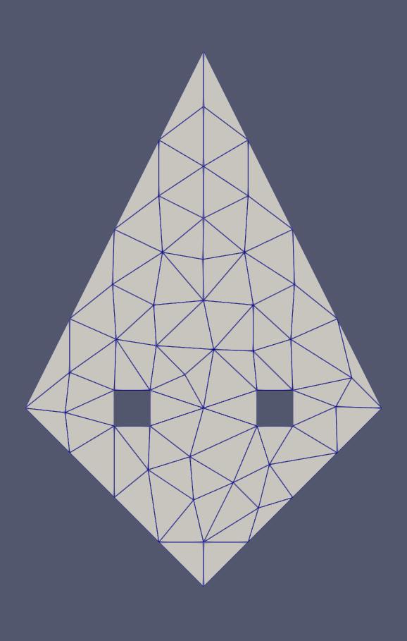
FlexiblePatternGenerator
FlexiblePatternGenerator is designed to generate a mesh with a background region containing dispersed unit meshes that are distributed based on a series of flexible patterns. It enhances the capabilities provided in PatternedHexMeshGenerator/PatternedCartesianMeshGenerator. It can be used for irregular background shapes and/or patterning.
[Mesh<<<{"href": "../../../../syntax/Mesh/index.html"}>>>]
  [fpg]
    type = FlexiblePatternGenerator<<<{"description": "This FlexiblePatternGenerator object is designed to generate a mesh with a background region with dispersed unit meshes in it and distributed based on a series of flexible patterns.", "href": "../../../../source/meshgenerators/FlexiblePatternGenerator.html"}>>>
    inputs<<<{"description": "The input MeshGenerators."}>>> = 'accg reduced_accg'
    boundary_type<<<{"description": "what type of boundary is used as background for patterning."}>>> = HEXAGON
    boundary_size<<<{"description": "The pitch size of the HEXAGON or CARTESIAN boundary mesh; or the diameter of the CIRCLE boundary mesh."}>>> = '${fparse 12.0*sqrt(3.0)}'
    boundary_sectors<<<{"description": "The number of sectors on each side of the HEXAGON or CARTESIAN boundary mesh or on the circular boundary of the CIRCLE boundary mesh."}>>> = 10
    hex_patterns<<<{"description": "Hexagonal patterns set."}>>> = '0 0;
                   0 2 0;
                    0 0'
    hex_pitches<<<{"description": "pitch sizes used to generate the hexagonal patterns."}>>> = 7
    rect_pitches_x<<<{"description": "pitch sizes in x direction used to generate the rectangular patterns."}>>> = 3
    rect_pitches_y<<<{"description": "pitch sizes in y direction used to generate the rectangular patterns."}>>> = 5
    rect_patterns<<<{"description": "Rectangular patterns set."}>>> = '1 1;
                     1 1'
    extra_positions<<<{"description": "The extra non-patterned positions to set the input MeshGenerators."}>>> = '0.0 10.0 0.0
                       0.0 -10.0 0.0'
    extra_positions_mg_indices<<<{"description": "the indices of the input mesh generators for the extra position."}>>> = '1 1'
    desired_area<<<{"description": "Desired are for the background area meshing."}>>> = 1.0
  []
[]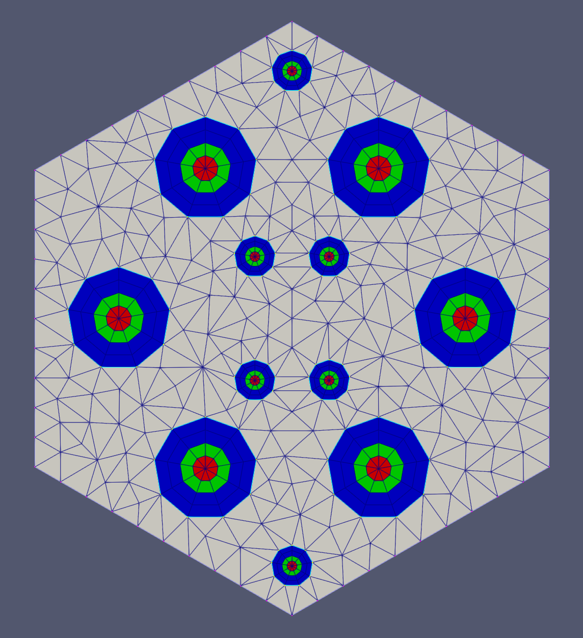
RevolveGenerator
RevolveGenerator provides an alternative tool for increasing the dimensionality of a lower dimension mesh (1D or 2D) in addition to MeshExtruderGenerator/AdvancedExtruderGenerator. Each element is converted to one or more copies of its corresponding higher dimensional element along an open or closed specific circular curve.
[Mesh<<<{"href": "../../../../syntax/Mesh/index.html"}>>>]
  [shg]
    type = SimpleHexagonGenerator<<<{"description": "This SimpleHexagonGenerator object is designed to generate a simple hexagonal mesh that only contains six simple azimuthal triangular elements, two quadrilateral elements, or six central azimuthal triangular elements plus a several layers of quadrilateral elements.", "href": "../../../../source/meshgenerators/SimpleHexagonGenerator.html"}>>>
    hexagon_size<<<{"description": "Size of the hexagon to be generated."}>>> = 1.0
    block_id<<<{"description": "Optional customized block id; two ids are needed for HYBRID 'element_type'."}>>> = '100 105'
    block_name<<<{"description": "Optional customized block name; two names are needed for HYBRID 'element_type'."}>>> = 'hex_tri hex'
    element_type<<<{"description": "Whether the simple hexagon mesh is made of TRI or QUAD elements."}>>> = HYBRID
    radial_intervals<<<{"description": "Number of pin radial meshing rings (only applicable when 'element_type' is 'HYBRID')."}>>> = 2
  []
  [rg]
    type = RevolveGenerator<<<{"description": "This RevolveGenerator object is designed to revolve a 1D mesh into 2D, or a 2D mesh into 3D based on an axis.", "href": "../../../../source/meshgenerators/RevolveGenerator.html"}>>>
    input<<<{"description": "The mesh to revolve"}>>> = shg
    axis_point<<<{"description": "A point on the axis of revolution"}>>> = '5.0 0.0 0.0'
    axis_direction<<<{"description": "The direction of the axis of revolution"}>>> = '0.0 1.0 0.0'
    nums_azimuthal_intervals<<<{"description": "List of the numbers of azimuthal interval discretization for each azimuthal section"}>>> = '4 8 16 32'
    revolving_angles<<<{"description": "The angles delineating each azimuthal section of revolution around the axis in degrees"}>>> = '20 40 60 80'
    subdomain_swaps<<<{"description": "For each row, every two entries are interpreted as a pair of 'from' and 'to' to remap the subdomains for that azimuthal section"}>>> = ' ;
                       100 200 105 205;
                       100 300 105 305;
                       100 110'
  []
[]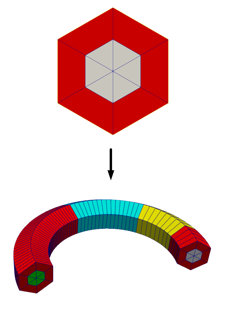
Advanced Meshing Examples
Possible Advanced Reactor Geometries
This tutorial covers the generation of mostly standard geometries, but many reactor designs involve features which were not covered previously. Using the tools covered in this section, MOOSE can generate quite complex geometries illustrated here. The key mesh generators required are listed briefly.
Molten Salt Reactor Experiment (MSRE) 2D lattice
PolygonConcentricCircleMeshGenerator is utilized for producing circular and triangular-shaped regions within the lattice
FillBetweenSidesetsGenerator is employed for generating mesh to fill in the regions between the regions generated by PolygonConcentricCircleMeshGenerator
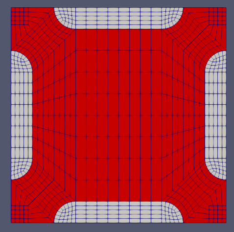
KRUSTY heat-pipe cooled microreactor 2D core
ParsedCurveGenerator is used for creating the outline of complex shapes before mesh generation.
XYDelaunayGenerator is employed for meshing the irregular areas.
PeripheralTriangleMeshGenerator is utilized to add layers of triangular mesh onto an existing circular mesh.
CircularBoundaryCorrectionGenerator is used to adjust a discretized circle to match the true circle's volume.
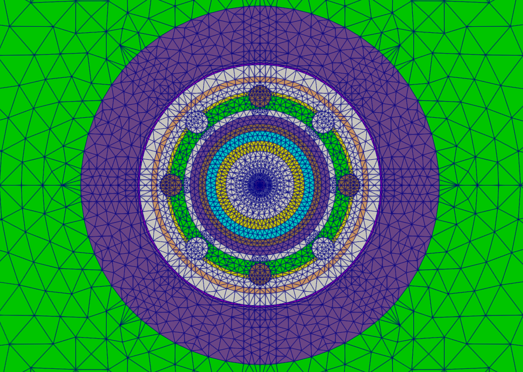
Modular High Temperature Gas Cooled Reactor (MHTGR)
PolygonConcentricCircleMeshGenerator and PatternedHexMeshGenerator generate pins and assemblies
XYDelaunayGenerator generates control rod holes and reflector assemblies
StitchMeshGenerator merges control rod holes with fuel and reflector assemblies
HexagonConcentricCircleAdaptiveBoundaryMeshGenerator generates ducts for reflector assembly that can be stitched with other assembles.
PatternedHexMeshGenerator generates a lattice of fuel and reflector assemblies into the core
PeripheralRingMeshGenerator adds a circular boundary surrounding the core
AdvancedExtruderGenerator performs 2D to 3D extrusion for the core
DepletionIDGenerator sets up assembly-wise depletion zones
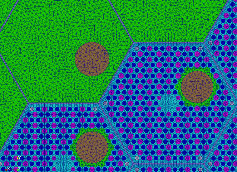
2D Pebble Bed Reactor with Streamlines
FillBetweenPointVectorsGenerator generates pebble bed streamlines
CartesianMeshGenerator and FillBetweenSidesetsGenerator generates rectangular meshes and trapezoid meshes
StitchMeshGenerator merges core components
CombinerGenerator combines outer walls of core barrel and RPV
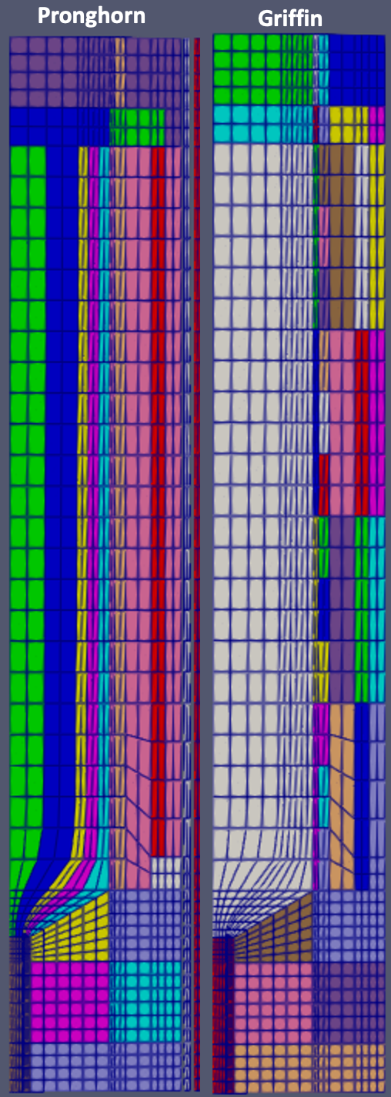
Boundary Layers and Biasing
During the mesh refinement process, it is common to require finer discretizations in one region and coarser discretizations in another region. The boundary layer and biasing features available in the Reactor Module allow the user to refine the mesh in areas of interest for the physics problem at hand.
Mesh Biasing
Mesh biasing applies non-uniform meshing subintervals within a specific region. For example, a fuel pin may generally require an axial meshing size of 5 cm, but at the very top and bottom of the active fuel zone where the power shape has a larger gradient, the user may require finer grids. This is possible using mesh biasing parameters available in AdvancedExtruderGenerator.
[Mesh<<<{"href": "../../../../syntax/Mesh/index.html"}>>>]
  [gmg]
    type = GeneratedMeshGenerator<<<{"description": "Create a line, square, or cube mesh with uniformly spaced or biased elements.", "href": "../../../../source/meshgenerators/GeneratedMeshGenerator.html"}>>>
    dim<<<{"description": "The dimension of the mesh to be generated"}>>> = 2
    nx<<<{"description": "Number of elements in the X direction"}>>> = 6
    ny<<<{"description": "Number of elements in the Y direction"}>>> = 6
    nz<<<{"description": "Number of elements in the Z direction"}>>> = 0
    zmin<<<{"description": "Lower Z Coordinate of the generated mesh"}>>> = 0
    zmax<<<{"description": "Upper Z Coordinate of the generated mesh"}>>> = 0
    elem_type<<<{"description": "The type of element from libMesh to generate (default: linear element for requested dimension)"}>>> = QUAD4
  []

  [extrude]
    type = AdvancedExtruderGenerator<<<{"description": "Extrudes a 1D mesh into 2D, or a 2D mesh into 3D, and supports a variable height for each elevation, variable number of layers within each elevation, variable growth factors of axial element sizes within each elevation and remap subdomain_ids, boundary_ids and element extra integers within each elevation as well as interface boundaries between neighboring elevation layers, as well as following a 1D curve and modifying the radial (normal to the extrusion axis) extent of the geometry.", "href": "../../../../source/meshgenerators/AdvancedExtruderGenerator.html"}>>>
    input<<<{"description": "The mesh to extrude"}>>> = gmg
    heights<<<{"description": "The height of each elevation"}>>> = '2 1 2'
    num_layers<<<{"description": "The number of layers for each elevation - must be num_elevations in length!"}>>> = '5 3 5'
    biases<<<{"description": "The axial growth factor used for mesh biasing for each elevation."}>>> = '1.6 1.0 0.625'
    direction<<<{"description": "A vector that points in the direction to extrude (note, this will be normalized internally - so don't worry about it here)"}>>> = '0 0 1'
    bottom_boundary<<<{"description": "The boundary name to set on the bottom boundary. If omitted an ID will be generated."}>>> = 4
    top_boundary<<<{"description": "The boundary name to set on the top boundary. If omitted an ID will be generated."}>>> = 5
    subdomain_swaps<<<{"description": "For each row, every two entries are interpreted as a pair of 'from' and 'to' to remap the subdomains for that elevation"}>>> = '0 1;
                         0 2;
                         0 3'
  []
[]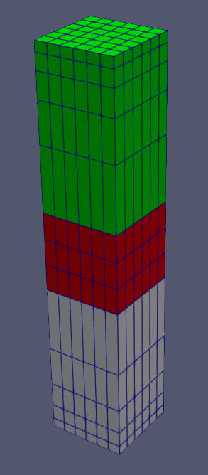
Radial Mesh Biasing
Similarly, the user may want to radially bias the mesh where solution gradients are known to be high, for example at the edge of a fuel pin or control rod. This is possible using mesh biasing parameters in PolygonConcentricCircleMeshGenerator as well as PeripheralRingMeshGenerator.
[Mesh<<<{"href": "../../../../syntax/Mesh/index.html"}>>>]
  [hex_1]
    type = PolygonConcentricCircleMeshGenerator<<<{"description": "This PolygonConcentricCircleMeshGenerator object is designed to mesh a polygon geometry with optional rings centered inside.", "href": "../../../../source/meshgenerators/PolygonConcentricCircleMeshGenerator.html"}>>>
    num_sides<<<{"description": "Number of sides of the polygon."}>>> = 6
    num_sectors_per_side<<<{"description": "Number of azimuthal sectors per polygon side (rotating counterclockwise from top right face)."}>>> = '4 4 4 4 4 4'
    background_intervals<<<{"description": "Number of radial meshing intervals in background region (area between rings and ducts) excluding the background's boundary layers."}>>> = 4
    ring_radii<<<{"description": "Radii of major concentric circles (rings)."}>>> = '2.0 4.0'
    ring_intervals<<<{"description": "Number of radial mesh intervals within each major concentric circle excluding their boundary layers."}>>> = '5 5'
    ring_block_ids<<<{"description": "Optional customized block ids for each ring geometry block."}>>> = '10 11 15'
    ring_block_names<<<{"description": "Optional customized block names for each ring geometry block."}>>> = 'center_tri center mid'
    background_block_ids<<<{"description": "Optional customized block id for the background block."}>>> = 20
    background_block_names<<<{"description": "Optional customized block names for the background block."}>>> = background
    polygon_size<<<{"description": "Size of the polygon to be generated (given as either apothem or radius depending on polygon_size_style)."}>>> = 5.0
    preserve_volumes<<<{"description": "Volume of concentric circles can be preserved using this function."}>>> = on
    ring_radial_biases<<<{"description": "Values used to create biasing in radial meshing for ring regions."}>>> = '1.0 1.6'
    background_radial_bias<<<{"description": "Value used to create biasing in radial meshing for background region."}>>> = 0.625
  []
[]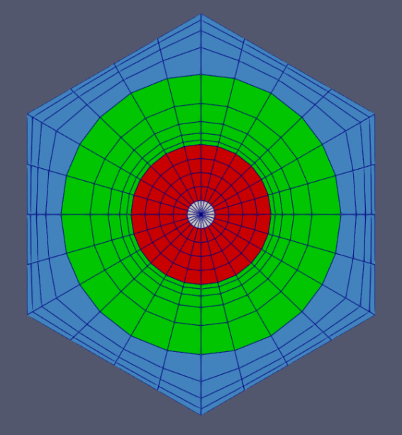
Radial Mesh Biasing in Core Periphery
[Mesh<<<{"href": "../../../../syntax/Mesh/index.html"}>>>]
  [hex_1]
    type = PolygonConcentricCircleMeshGenerator<<<{"description": "This PolygonConcentricCircleMeshGenerator object is designed to mesh a polygon geometry with optional rings centered inside.", "href": "../../../../source/meshgenerators/PolygonConcentricCircleMeshGenerator.html"}>>>
    num_sides<<<{"description": "Number of sides of the polygon."}>>> = 6
    num_sectors_per_side<<<{"description": "Number of azimuthal sectors per polygon side (rotating counterclockwise from top right face)."}>>> = '4 4 4 4 4 4'
    background_intervals<<<{"description": "Number of radial meshing intervals in background region (area between rings and ducts) excluding the background's boundary layers."}>>> = 2
    ring_radii<<<{"description": "Radii of major concentric circles (rings)."}>>> = '4.0'
    ring_intervals<<<{"description": "Number of radial mesh intervals within each major concentric circle excluding their boundary layers."}>>> = '2'
    ring_block_ids<<<{"description": "Optional customized block ids for each ring geometry block."}>>> = '10 15'
    ring_block_names<<<{"description": "Optional customized block names for each ring geometry block."}>>> = 'center_tri center'
    background_block_ids<<<{"description": "Optional customized block id for the background block."}>>> = 20
    background_block_names<<<{"description": "Optional customized block names for the background block."}>>> = background
    polygon_size<<<{"description": "Size of the polygon to be generated (given as either apothem or radius depending on polygon_size_style)."}>>> = 5.0
    preserve_volumes<<<{"description": "Volume of concentric circles can be preserved using this function."}>>> = on
    background_radial_bias<<<{"description": "Value used to create biasing in radial meshing for background region."}>>> = 0.625
  []
  [peripheral_ring]
    type = PeripheralRingMeshGenerator<<<{"description": "This PeripheralRingMeshGenerator object adds a circular peripheral region to the input mesh.", "href": "../../../../source/meshgenerators/PeripheralRingMeshGenerator.html"}>>>
    input<<<{"description": "The input mesh to be modified."}>>> = hex_1
    peripheral_ring_block_id<<<{"description": "The block id assigned to the created peripheral layer."}>>> = 200
    peripheral_layer_num<<<{"description": "The radial layers of the peripheral ring to be added."}>>> = 5
    input_mesh_external_boundary<<<{"description": "The external boundary of the input mesh."}>>> = 10000
    peripheral_ring_radius<<<{"description": "Radius of the peripheral ring to be added."}>>> = 8
    peripheral_radial_bias<<<{"description": "Value used to create biasing in radial meshing for peripheral ring region."}>>> = 0.625
  []
[]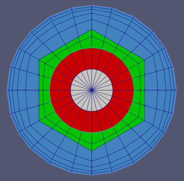
Mesh Boundary Layers
Boundary layers are commonly needed in thermal-hydraulic applications, where the thickness of the mesh near a wall must be a certain size, uniformly, regardless of the width of the meshed region. Boundary layers are possible using PolygonConcentricCircleMeshGenerator and PeripheralRingMeshGenerator.
[Mesh<<<{"href": "../../../../syntax/Mesh/index.html"}>>>]
  [hex_1]
    type = PolygonConcentricCircleMeshGenerator<<<{"description": "This PolygonConcentricCircleMeshGenerator object is designed to mesh a polygon geometry with optional rings centered inside.", "href": "../../../../source/meshgenerators/PolygonConcentricCircleMeshGenerator.html"}>>>
    num_sides<<<{"description": "Number of sides of the polygon."}>>> = 6
    num_sectors_per_side<<<{"description": "Number of azimuthal sectors per polygon side (rotating counterclockwise from top right face)."}>>> = '4 4 4 4 4 4'
    background_intervals<<<{"description": "Number of radial meshing intervals in background region (area between rings and ducts) excluding the background's boundary layers."}>>> = 2
    ring_radii<<<{"description": "Radii of major concentric circles (rings)."}>>> = '2.0 4.0'
    ring_intervals<<<{"description": "Number of radial mesh intervals within each major concentric circle excluding their boundary layers."}>>> = '2 2'
    ring_block_ids<<<{"description": "Optional customized block ids for each ring geometry block."}>>> = '10 11 15'
    ring_block_names<<<{"description": "Optional customized block names for each ring geometry block."}>>> = 'center_tri center mid'
    background_block_ids<<<{"description": "Optional customized block id for the background block."}>>> = 20
    background_block_names<<<{"description": "Optional customized block names for the background block."}>>> = background
    polygon_size<<<{"description": "Size of the polygon to be generated (given as either apothem or radius depending on polygon_size_style)."}>>> = 5.0
    preserve_volumes<<<{"description": "Volume of concentric circles can be preserved using this function."}>>> = on
    ## Background boundary layer setting
    background_inner_boundary_layer_bias<<<{"description": "Growth factor used for mesh biasing of the background inner boundary layer."}>>> = 1.6
    background_inner_boundary_layer_intervals<<<{"description": "Number of radial intervals of the background inner boundary layer"}>>> = 3
    background_inner_boundary_layer_width<<<{"description": "Width of background region that is assigned to be the inner boundary layer."}>>> = 0.4
    ## Ring boundary layer setting
    ring_outer_boundary_layer_biases<<<{"description": "Growth factors used for mesh biasing of the rings' outer boundary layers."}>>> = '1.0 0.625'
    ring_outer_boundary_layer_intervals<<<{"description": "Number of radial intervals of the rings' outer boundary layers"}>>> = '0 3'
    ring_outer_boundary_layer_widths<<<{"description": "Widths of each ring regions that are assigned to be each ring's outer boundary layers."}>>> = '0.0 0.5'
  []
[]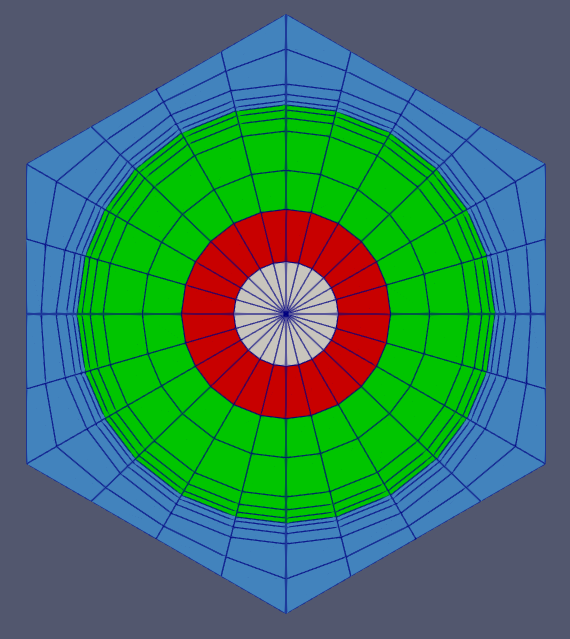
Stitching Assemblies with Different Pin Numbers
Typical reactor cores are comprised of many different assembly types, each with different numbers of pins. It is difficult to find a reasonably low azimuthal discretization for each assembly such that all assemblies have the same number of nodes on their boundaries.
The best approach for this situation is to use PatternedHexPeripheralModifier to strip the outermost layer off each assembly and replace it with a transition layer with a set number of nodes on the outermost boundary.
[Mesh<<<{"href": "../../../../syntax/Mesh/index.html"}>>>]
  [hex_1]
    type = PolygonConcentricCircleMeshGenerator<<<{"description": "This PolygonConcentricCircleMeshGenerator object is designed to mesh a polygon geometry with optional rings centered inside.", "href": "../../../../source/meshgenerators/PolygonConcentricCircleMeshGenerator.html"}>>>
    num_sides<<<{"description": "Number of sides of the polygon."}>>> = 6
    num_sectors_per_side<<<{"description": "Number of azimuthal sectors per polygon side (rotating counterclockwise from top right face)."}>>> = '2 2 2 2 2 2'
    background_intervals<<<{"description": "Number of radial meshing intervals in background region (area between rings and ducts) excluding the background's boundary layers."}>>> = 1
    ring_radii<<<{"description": "Radii of major concentric circles (rings)."}>>> = 4.0
    ring_intervals<<<{"description": "Number of radial mesh intervals within each major concentric circle excluding their boundary layers."}>>> = 1
    ring_block_ids<<<{"description": "Optional customized block ids for each ring geometry block."}>>> = '10'
    ring_block_names<<<{"description": "Optional customized block names for each ring geometry block."}>>> = 'center_1'
    background_block_ids<<<{"description": "Optional customized block id for the background block."}>>> = 20
    background_block_names<<<{"description": "Optional customized block names for the background block."}>>> = background_1
    polygon_size<<<{"description": "Size of the polygon to be generated (given as either apothem or radius depending on polygon_size_style)."}>>> = 5.0
    preserve_volumes<<<{"description": "Volume of concentric circles can be preserved using this function."}>>> = on
    quad_center_elements<<<{"description": "Whether the center elements are quad or triangular."}>>> = true
  []
  [pattern_1]
    type = PatternedHexMeshGenerator<<<{"description": "This PatternedHexMeshGenerator source code assembles hexagonal meshes into a hexagonal grid and optionally forces the outer boundary to be hexagonal and/or adds a duct.", "href": "../../../../source/meshgenerators/PatternedHexMeshGenerator.html"}>>>
    inputs<<<{"description": "The input MeshGenerators."}>>> = 'hex_1'
    pattern<<<{"description": "A double-indexed hexagonal-shaped array starting with the upper-left corner."}>>> = '0 0;
              0 0 0;
               0 0'
    background_intervals<<<{"description": "Radial intervals in the assembly peripheral region."}>>> = 1
    hexagon_size<<<{"description": "Size of the outmost hexagon boundary to be generated; this is required only when pattern type is 'hexagon'."}>>> = 17
    #duct_sizes = '15 15.5'
    #duct_intervals = '1 2'
  []
  [pmg_1]
    type = PatternedHexPeripheralModifier<<<{"description": "PatternedPolygonPeripheralModifierBase is the base class for PatternedCartPeripheralModifier and PatternedHexPeripheralModifier.", "href": "../../../../source/meshgenerators/PatternedHexPeripheralModifier.html"}>>>
    input<<<{"description": "The input mesh to be modified. Note that this generator only works with PatternedHex/CartesianMeshGenerator and its derived classes such as HexIDPatternedMeshGenerator."}>>> = pattern_1
    input_mesh_external_boundary<<<{"description": "The external boundary of the input mesh."}>>> = 10000
    new_num_sector<<<{"description": "Number of sectors of each side for the new mesh."}>>> = ${new_num_sector}
    num_layers<<<{"description": "Layers of elements for transition."}>>> = ${num_layer}
  []
  [hex_2]
    type = PolygonConcentricCircleMeshGenerator<<<{"description": "This PolygonConcentricCircleMeshGenerator object is designed to mesh a polygon geometry with optional rings centered inside.", "href": "../../../../source/meshgenerators/PolygonConcentricCircleMeshGenerator.html"}>>>
    num_sides<<<{"description": "Number of sides of the polygon."}>>> = 6
    num_sectors_per_side<<<{"description": "Number of azimuthal sectors per polygon side (rotating counterclockwise from top right face)."}>>> = '2 2 2 2 2 2'
    background_intervals<<<{"description": "Number of radial meshing intervals in background region (area between rings and ducts) excluding the background's boundary layers."}>>> = 1
    ring_radii<<<{"description": "Radii of major concentric circles (rings)."}>>> = 2.5
    ring_intervals<<<{"description": "Number of radial mesh intervals within each major concentric circle excluding their boundary layers."}>>> = 1
    ring_block_ids<<<{"description": "Optional customized block ids for each ring geometry block."}>>> = '30'
    ring_block_names<<<{"description": "Optional customized block names for each ring geometry block."}>>> = 'center_2'
    background_block_ids<<<{"description": "Optional customized block id for the background block."}>>> = 40
    background_block_names<<<{"description": "Optional customized block names for the background block."}>>> = background_2
    polygon_size<<<{"description": "Size of the polygon to be generated (given as either apothem or radius depending on polygon_size_style)."}>>> = 3.0
    preserve_volumes<<<{"description": "Volume of concentric circles can be preserved using this function."}>>> = on
    quad_center_elements<<<{"description": "Whether the center elements are quad or triangular."}>>> = true
  []
  [pattern_2]
    type = PatternedHexMeshGenerator<<<{"description": "This PatternedHexMeshGenerator source code assembles hexagonal meshes into a hexagonal grid and optionally forces the outer boundary to be hexagonal and/or adds a duct.", "href": "../../../../source/meshgenerators/PatternedHexMeshGenerator.html"}>>>
    inputs<<<{"description": "The input MeshGenerators."}>>> = 'hex_2'
    pattern<<<{"description": "A double-indexed hexagonal-shaped array starting with the upper-left corner."}>>> = '0 0 0;
              0 0 0 0;
             0 0 0 0 0;
              0 0 0 0;
               0 0 0'
    background_intervals<<<{"description": "Radial intervals in the assembly peripheral region."}>>> = 1
    hexagon_size<<<{"description": "Size of the outmost hexagon boundary to be generated; this is required only when pattern type is 'hexagon'."}>>> = 17
    #duct_sizes = '15 15.5'
    #duct_intervals = '1 2'
  []
  [pmg_2]
    type = PatternedHexPeripheralModifier<<<{"description": "PatternedPolygonPeripheralModifierBase is the base class for PatternedCartPeripheralModifier and PatternedHexPeripheralModifier.", "href": "../../../../source/meshgenerators/PatternedHexPeripheralModifier.html"}>>>
    input<<<{"description": "The input mesh to be modified. Note that this generator only works with PatternedHex/CartesianMeshGenerator and its derived classes such as HexIDPatternedMeshGenerator."}>>> = pattern_2
    input_mesh_external_boundary<<<{"description": "The external boundary of the input mesh."}>>> = 10000
    new_num_sector<<<{"description": "Number of sectors of each side for the new mesh."}>>> = ${new_num_sector}
    num_layers<<<{"description": "Layers of elements for transition."}>>> = ${num_layer}
  []
  [hex_3]
    type = PolygonConcentricCircleMeshGenerator<<<{"description": "This PolygonConcentricCircleMeshGenerator object is designed to mesh a polygon geometry with optional rings centered inside.", "href": "../../../../source/meshgenerators/PolygonConcentricCircleMeshGenerator.html"}>>>
    num_sides<<<{"description": "Number of sides of the polygon."}>>> = 6
    num_sectors_per_side<<<{"description": "Number of azimuthal sectors per polygon side (rotating counterclockwise from top right face)."}>>> = '2 2 2 2 2 2'
    background_intervals<<<{"description": "Number of radial meshing intervals in background region (area between rings and ducts) excluding the background's boundary layers."}>>> = 1
    ring_radii<<<{"description": "Radii of major concentric circles (rings)."}>>> = 1.5
    ring_intervals<<<{"description": "Number of radial mesh intervals within each major concentric circle excluding their boundary layers."}>>> = 1
    ring_block_ids<<<{"description": "Optional customized block ids for each ring geometry block."}>>> = '50'
    ring_block_names<<<{"description": "Optional customized block names for each ring geometry block."}>>> = 'center_3'
    background_block_ids<<<{"description": "Optional customized block id for the background block."}>>> = 60
    background_block_names<<<{"description": "Optional customized block names for the background block."}>>> = background_3
    polygon_size<<<{"description": "Size of the polygon to be generated (given as either apothem or radius depending on polygon_size_style)."}>>> = 2.3
    preserve_volumes<<<{"description": "Volume of concentric circles can be preserved using this function."}>>> = on
    quad_center_elements<<<{"description": "Whether the center elements are quad or triangular."}>>> = true
  []
  [pattern_3]
    type = PatternedHexMeshGenerator<<<{"description": "This PatternedHexMeshGenerator source code assembles hexagonal meshes into a hexagonal grid and optionally forces the outer boundary to be hexagonal and/or adds a duct.", "href": "../../../../source/meshgenerators/PatternedHexMeshGenerator.html"}>>>
    inputs<<<{"description": "The input MeshGenerators."}>>> = 'hex_3'
    pattern<<<{"description": "A double-indexed hexagonal-shaped array starting with the upper-left corner."}>>> = '0 0 0 0;
              0 0 0 0 0;
             0 0 0 0 0 0;
            0 0 0 0 0 0 0;
             0 0 0 0 0 0;
              0 0 0 0 0;
               0 0 0 0'
    background_intervals<<<{"description": "Radial intervals in the assembly peripheral region."}>>> = 1
    hexagon_size<<<{"description": "Size of the outmost hexagon boundary to be generated; this is required only when pattern type is 'hexagon'."}>>> = 17
    #duct_sizes = '15 15.5'
    #duct_intervals = '1 2'
  []
  [pmg_3]
    type = PatternedHexPeripheralModifier<<<{"description": "PatternedPolygonPeripheralModifierBase is the base class for PatternedCartPeripheralModifier and PatternedHexPeripheralModifier.", "href": "../../../../source/meshgenerators/PatternedHexPeripheralModifier.html"}>>>
    input<<<{"description": "The input mesh to be modified. Note that this generator only works with PatternedHex/CartesianMeshGenerator and its derived classes such as HexIDPatternedMeshGenerator."}>>> = pattern_3
    input_mesh_external_boundary<<<{"description": "The external boundary of the input mesh."}>>> = 10000
    new_num_sector<<<{"description": "Number of sectors of each side for the new mesh."}>>> = ${new_num_sector}
    num_layers<<<{"description": "Layers of elements for transition."}>>> = ${num_layer}
  []
  [hex_4]
    type = PolygonConcentricCircleMeshGenerator<<<{"description": "This PolygonConcentricCircleMeshGenerator object is designed to mesh a polygon geometry with optional rings centered inside.", "href": "../../../../source/meshgenerators/PolygonConcentricCircleMeshGenerator.html"}>>>
    num_sides<<<{"description": "Number of sides of the polygon."}>>> = 6
    num_sectors_per_side<<<{"description": "Number of azimuthal sectors per polygon side (rotating counterclockwise from top right face)."}>>> = '2 2 2 2 2 2'
    background_intervals<<<{"description": "Number of radial meshing intervals in background region (area between rings and ducts) excluding the background's boundary layers."}>>> = 1
    ring_radii<<<{"description": "Radii of major concentric circles (rings)."}>>> = 1.4
    ring_intervals<<<{"description": "Number of radial mesh intervals within each major concentric circle excluding their boundary layers."}>>> = 1
    ring_block_ids<<<{"description": "Optional customized block ids for each ring geometry block."}>>> = '70'
    ring_block_names<<<{"description": "Optional customized block names for each ring geometry block."}>>> = 'center_4'
    background_block_ids<<<{"description": "Optional customized block id for the background block."}>>> = 80
    background_block_names<<<{"description": "Optional customized block names for the background block."}>>> = background_4
    polygon_size<<<{"description": "Size of the polygon to be generated (given as either apothem or radius depending on polygon_size_style)."}>>> = 1.8
    preserve_volumes<<<{"description": "Volume of concentric circles can be preserved using this function."}>>> = on
    quad_center_elements<<<{"description": "Whether the center elements are quad or triangular."}>>> = true
  []
  [pattern_4]
    type = PatternedHexMeshGenerator<<<{"description": "This PatternedHexMeshGenerator source code assembles hexagonal meshes into a hexagonal grid and optionally forces the outer boundary to be hexagonal and/or adds a duct.", "href": "../../../../source/meshgenerators/PatternedHexMeshGenerator.html"}>>>
    inputs<<<{"description": "The input MeshGenerators."}>>> = 'hex_4'
    pattern<<<{"description": "A double-indexed hexagonal-shaped array starting with the upper-left corner."}>>> = '0 0 0 0 0;
              0 0 0 0 0 0;
             0 0 0 0 0 0 0;
            0 0 0 0 0 0 0 0;
           0 0 0 0 0 0 0 0 0;
            0 0 0 0 0 0 0 0;
             0 0 0 0 0 0 0;
              0 0 0 0 0 0;
               0 0 0 0 0'
    background_intervals<<<{"description": "Radial intervals in the assembly peripheral region."}>>> = 1
    hexagon_size<<<{"description": "Size of the outmost hexagon boundary to be generated; this is required only when pattern type is 'hexagon'."}>>> = 17
    #duct_sizes = '15 15.5'
    #duct_intervals = '1 2'
  []
  [pmg_4]
    type = PatternedHexPeripheralModifier<<<{"description": "PatternedPolygonPeripheralModifierBase is the base class for PatternedCartPeripheralModifier and PatternedHexPeripheralModifier.", "href": "../../../../source/meshgenerators/PatternedHexPeripheralModifier.html"}>>>
    input<<<{"description": "The input mesh to be modified. Note that this generator only works with PatternedHex/CartesianMeshGenerator and its derived classes such as HexIDPatternedMeshGenerator."}>>> = pattern_4
    input_mesh_external_boundary<<<{"description": "The external boundary of the input mesh."}>>> = 10000
    new_num_sector<<<{"description": "Number of sectors of each side for the new mesh."}>>> = ${new_num_sector}
    num_layers<<<{"description": "Layers of elements for transition."}>>> = ${num_layer}
  []
  [pattern_sum]
    type = PatternedHexMeshGenerator<<<{"description": "This PatternedHexMeshGenerator source code assembles hexagonal meshes into a hexagonal grid and optionally forces the outer boundary to be hexagonal and/or adds a duct.", "href": "../../../../source/meshgenerators/PatternedHexMeshGenerator.html"}>>>
    inputs<<<{"description": "The input MeshGenerators."}>>> = 'pmg_1 pmg_2 pmg_3 pmg_4'
    pattern<<<{"description": "A double-indexed hexagonal-shaped array starting with the upper-left corner."}>>> = '2 3;
              1 0 1;
               3 2'
    pattern_boundary<<<{"description": "The boundary shape of the patterned mesh."}>>> = none
    generate_core_metadata<<<{"description": "A Boolean parameter that controls whether the core related metadata is generated for other MOOSE objects such as 'MultiControlDrumFunction' or not."}>>> = true
  []
[]
Oversized Pin
Some assemblies contain one or multiple oversized pins which intrude on neighboring unit pin cells. Meshing of such oversized pins has become straightforward with FlexiblePatternGenerator
As long as pins are not overlapped, FlexiblePatternGenerator can handle any oversized pin scenarios.
[Mesh<<<{"href": "../../../../syntax/Mesh/index.html"}>>>]
  [pin_regular]
    type = AdvancedConcentricCircleGenerator<<<{"description": "This AdvancedConcentricCircleGenerator object is designed to mesh a concentric circular geometry.", "href": "../../../../source/meshgenerators/AdvancedConcentricCircleGenerator.html"}>>>
    num_sectors<<<{"description": "Number of azimuthal sectors of the circular mesh to be generated."}>>> = 12
    ring_radii<<<{"description": "Radii of major concentric circles (rings)."}>>> = '1 2'
    ring_intervals<<<{"description": "Number of radial mesh intervals within each major concentric circle excluding their boundary layers."}>>> = '2 2'
    ring_block_ids<<<{"description": "Optional customized block ids for each ring geometry block."}>>> = '10 15 20'
    ring_block_names<<<{"description": "Optional customized block names for each ring geometry block."}>>> = 'inner_tri inner outer'
    external_boundary_id<<<{"description": "Optional customized external boundary id."}>>> = 100
    external_boundary_name<<<{"description": "Optional customized external boundary name."}>>> = 'ext'
    create_outward_interface_boundaries<<<{"description": "Whether the outward interface boundaries are created."}>>> = false
  []
  [pin_oversize]
    type = AdvancedConcentricCircleGenerator<<<{"description": "This AdvancedConcentricCircleGenerator object is designed to mesh a concentric circular geometry.", "href": "../../../../source/meshgenerators/AdvancedConcentricCircleGenerator.html"}>>>
    num_sectors<<<{"description": "Number of azimuthal sectors of the circular mesh to be generated."}>>> = 12
    ring_radii<<<{"description": "Radii of major concentric circles (rings)."}>>> = '2 3'
    ring_intervals<<<{"description": "Number of radial mesh intervals within each major concentric circle excluding their boundary layers."}>>> = '2 2'
    ring_block_ids<<<{"description": "Optional customized block ids for each ring geometry block."}>>> = '30 35 40'
    ring_block_names<<<{"description": "Optional customized block names for each ring geometry block."}>>> = 'inner_os_tri inner_os outer_os'
    external_boundary_id<<<{"description": "Optional customized external boundary id."}>>> = 100
    external_boundary_name<<<{"description": "Optional customized external boundary name."}>>> = 'ext'
    create_outward_interface_boundaries<<<{"description": "Whether the outward interface boundaries are created."}>>> = false
  []
  [fpg]
    type = FlexiblePatternGenerator<<<{"description": "This FlexiblePatternGenerator object is designed to generate a mesh with a background region with dispersed unit meshes in it and distributed based on a series of flexible patterns.", "href": "../../../../source/meshgenerators/FlexiblePatternGenerator.html"}>>>
    inputs<<<{"description": "The input MeshGenerators."}>>> = 'pin_regular pin_oversize'
    boundary_type<<<{"description": "what type of boundary is used as background for patterning."}>>> = HEXAGON
    boundary_sectors<<<{"description": "The number of sectors on each side of the HEXAGON or CARTESIAN boundary mesh or on the circular boundary of the CIRCLE boundary mesh."}>>> = 10
    boundary_size<<<{"description": "The pitch size of the HEXAGON or CARTESIAN boundary mesh; or the diameter of the CIRCLE boundary mesh."}>>> = '${fparse 22.0*sqrt(3.0)}'
    hex_patterns<<<{"description": "Hexagonal patterns set."}>>> = '0 0 0 0;
                   0 1 0 1 0;
                  0 0 0 0 0 0;
                 0 0 0 1 0 0 0;
                  0 0 0 0 0 0;
                   0 1 0 1 0;
                    0 0 0 0'
    hex_pitches<<<{"description": "pitch sizes used to generate the hexagonal patterns."}>>> = '5.5'
    hex_origins<<<{"description": "the origin positions of the hexagonal patterns,"}>>> = '0.0 0.0 0.0'
    use_auto_area_func<<<{"description": "Use the automatic area function for triangle-meshing in the background."}>>> = true
  []
[]
Filling Between Curves using "FillBetweenSidesetsGenerator"
The MSRE 2D lattice case was constructed using the FillBetweenSidesetsGenerator to connect "quarter" circular pins. First, ConcentricCircleMeshGenerator (a predecessor of PolygonConcentricCircleMeshGenerator which has a different set of input options and works only for square pin cells) was used to create two quarter pins.
[Mesh<<<{"href": "../../../../syntax/Mesh/index.html"}>>>]
  [connect_two_circles]
    type = FillBetweenSidesetsGenerator<<<{"description": "This FillBetweenSidesetsGenerator object is designed to generate a transition layer to connect two boundaries of two input meshes.", "href": "../../../../source/meshgenerators/FillBetweenSidesetsGenerator.html"}>>>
    input_mesh_1<<<{"description": "The input mesh that contains boundary_1"}>>> = 'Corner_bottom_left_2'
    input_mesh_2<<<{"description": "The input mesh that contains boundary_2"}>>> = 'Corner_top_right_3'
    boundary_1<<<{"description": "the first boundary that needs to be connected."}>>> = 'curve_1'
    boundary_2<<<{"description": "the second boundary that needs to be connected."}>>> = 'curve_2'
    num_layers<<<{"description": "Number of layers of elements created between the boundaries."}>>> = 8
    keep_inputs<<<{"description": "Whether to output the input meshes stitched with the transition layer connector."}>>> = true
    use_quad_elements<<<{"description": "Whether QUAD4 instead of TRI3 elements are used to construct the transition layer."}>>> = true
    block_id<<<{"description": "ID to be assigned to the transition layer."}>>> = 200
  []
[]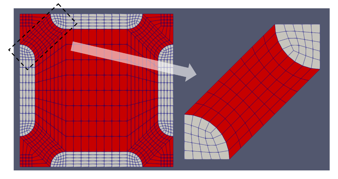
Triangulation of Odd-Shaped Regions Using "ParsedCurveGenerator" and "XYDelaunayGenerator"
This example demonstrates how to place a control drum object in an arbitrary position in a core that may overlap subdomain boundaries.
First, the center assembly is created using regular pins and procedures.
[Mesh<<<{"href": "../../../../syntax/Mesh/index.html"}>>>]
  [hex_1]
    type = PolygonConcentricCircleMeshGenerator<<<{"description": "This PolygonConcentricCircleMeshGenerator object is designed to mesh a polygon geometry with optional rings centered inside.", "href": "../../../../source/meshgenerators/PolygonConcentricCircleMeshGenerator.html"}>>>
    num_sides<<<{"description": "Number of sides of the polygon."}>>> = 6
    num_sectors_per_side<<<{"description": "Number of azimuthal sectors per polygon side (rotating counterclockwise from top right face)."}>>> = '2 2 2 2 2 2'
    background_intervals<<<{"description": "Number of radial meshing intervals in background region (area between rings and ducts) excluding the background's boundary layers."}>>> = 2
    ring_radii<<<{"description": "Radii of major concentric circles (rings)."}>>> = 4.0
    ring_intervals<<<{"description": "Number of radial mesh intervals within each major concentric circle excluding their boundary layers."}>>> = 2
    ring_block_ids<<<{"description": "Optional customized block ids for each ring geometry block."}>>> = '10 15'
    ring_block_names<<<{"description": "Optional customized block names for each ring geometry block."}>>> = 'pin_tri pin_quad'
    background_block_ids<<<{"description": "Optional customized block id for the background block."}>>> = 20
    background_block_names<<<{"description": "Optional customized block names for the background block."}>>> = pin_background
    polygon_size<<<{"description": "Size of the polygon to be generated (given as either apothem or radius depending on polygon_size_style)."}>>> = 5.0
    preserve_volumes<<<{"description": "Volume of concentric circles can be preserved using this function."}>>> = on
  []

  [pattern]
    type = PatternedHexMeshGenerator<<<{"description": "This PatternedHexMeshGenerator source code assembles hexagonal meshes into a hexagonal grid and optionally forces the outer boundary to be hexagonal and/or adds a duct.", "href": "../../../../source/meshgenerators/PatternedHexMeshGenerator.html"}>>>
    inputs<<<{"description": "The input MeshGenerators."}>>> = 'hex_1'
    hexagon_size<<<{"description": "Size of the outmost hexagon boundary to be generated; this is required only when pattern type is 'hexagon'."}>>> = 25
    background_block_id<<<{"description": "Optional customized block id for the background block in 'assembly' mode; must be provided along with 'duct_block_ids' if 'duct_sizes' is provided."}>>> = 30
    background_block_name<<<{"description": "Optional customized block name for the background block in 'assembly' mode; must be provided along with 'duct_block_names' if 'duct_sizes' is provided."}>>> = assembly_background
    pattern<<<{"description": "A double-indexed hexagonal-shaped array starting with the upper-left corner."}>>> = '0 0 0;
                0 0 0 0;
               0 0 0 0 0;
                0 0 0 0;
                 0 0 0'
  []
[]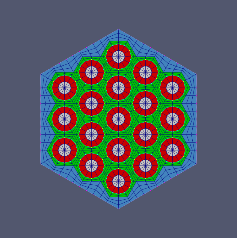
Triangulation of Odd-Shaped Regions (cont.)
Next, two circular peripheral regions are added using PeripheralTriangleMeshGenerator (yellow, purple zones).
[Mesh<<<{"href": "../../../../syntax/Mesh/index.html"}>>>]
  [tmg1]
    type = PeripheralTriangleMeshGenerator<<<{"description": "This PeripheralTriangleMeshGenerator object is designed to generate a triangulated mesh between a generated outer circle boundary and a provided inner mesh.", "href": "../../../../source/meshgenerators/PeripheralTriangleMeshGenerator.html"}>>>
    input<<<{"description": "The input mesh to be modified."}>>> = pattern
    peripheral_ring_radius<<<{"description": "Radius of the peripheral ring to be added."}>>> = 35
    peripheral_ring_num_segments<<<{"description": "Number of segments of the peripheral ring."}>>> = 50
    peripheral_ring_block_name<<<{"description": "The block name assigned to the created peripheral layer."}>>> = peripheral_1
    desired_area<<<{"description": "Desired (maximum) triangle area, or 0 to skip uniform refinement"}>>> = 8
  []

  [tmg2]
    type = PeripheralTriangleMeshGenerator<<<{"description": "This PeripheralTriangleMeshGenerator object is designed to generate a triangulated mesh between a generated outer circle boundary and a provided inner mesh.", "href": "../../../../source/meshgenerators/PeripheralTriangleMeshGenerator.html"}>>>
    input<<<{"description": "The input mesh to be modified."}>>> = tmg1
    peripheral_ring_radius<<<{"description": "Radius of the peripheral ring to be added."}>>> = 38
    peripheral_ring_num_segments<<<{"description": "Number of segments of the peripheral ring."}>>> = 80
    peripheral_ring_block_name<<<{"description": "The block name assigned to the created peripheral layer."}>>> = peripheral_2
    desired_area<<<{"description": "Desired (maximum) triangle area, or 0 to skip uniform refinement"}>>> = 6
  []
[]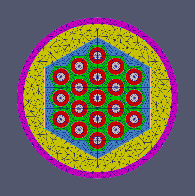
Triangulation of Odd-Shaped Regions (cont.)
Next, the complex boundary shape which is the outer edge of the light blue zone is defined using ParsedCurveGenerator and analytic piecewise functions. The interior of this boundary is then filled in, including the center assembly, using XYDelaunayGenerator.
[Mesh<<<{"href": "../../../../syntax/Mesh/index.html"}>>>]
  [pcg1]
    type = ParsedCurveGenerator<<<{"description": "This ParsedCurveGenerator object is designed to generate a mesh of a curve that consists of EDGE2, EDGE3, or EDGE4 elements.", "href": "../../../../source/meshgenerators/ParsedCurveGenerator.html"}>>>
    x_formula<<<{"description": "Function expression of x(t)"}>>> = 't1:=t;
                     t2:=t-1;
                     t3:=t-2;
                     t4:=t-3;
                     x1:=r*cos(t1*(th1-th0)+th0);
                     x2_0:=r*cos(th1);
                     x2_1:=x2_0-Lx;
                     x2:=x2_0+(x2_1-x2_0)*t2;
                     rs:=abs(r*sin(th1));
                     rth0:=1.5*pi;
                     rth1:=0.5*pi;
                     x3:=x2_1+rs*cos(rth0+(rth1-rth0)*t3);
                     x4_1:=r*cos(th1);
                     x4_0:=x4_1-Lx;
                     x4:=x4_0+(x4_1-x4_0)*t4;
                     if(t<1,x1,if(t<2,x2,if(t<3,x3,x4)))'
    y_formula<<<{"description": "Function expression of y(t)"}>>> = 't1:=t;
                     t2:=t-1;
                     t3:=t-2;
                     t4:=t-3;
                     y1:=r*sin(t1*(th1-th0)+th0);
                     y2:=r*sin(th1);
                     rs:=abs(r*sin(th1));
                     rth0:=1.5*pi;
                     rth1:=0.5*pi;
                     y3:=rs*sin(rth0+(rth1-rth0)*t3);
                     y4:=r*sin(th0);
                     if(t<1,y1,if(t<2,y2,if(t<3,y3,y4)))'
    section_bounding_t_values<<<{"description": "The 't' values that bound the sections of the curve. Start and end points must be included. The number of entries in 'nums_segments' should be equal to one less than the number of entries in this parameter."}>>> = '0 1 2 3 4'
    constant_names<<<{"description": "Vector of constants used in the parsed function (use this for kB etc.)"}>>> = 'pi           r    th0               th1                    Lx'
    constant_expressions<<<{"description": "Vector of values for the constants in constant_names (can be an FParser expression)"}>>> = '${fparse pi} 100.0 ${fparse pi/9.0} ${fparse pi/9.0*17.0} 10.0'
    nums_segments<<<{"description": "Numbers of segments (EDGE elements) of each section of the curve to be generated. The number of entries in this parameter should be equal to one less than the number of entries in 'section_bounding_t_values'"}>>> = '50 3 15 3'
    is_closed_loop<<<{"description": "Whether the curve is closed or not."}>>> = true
  []

  [xydg1]
    type = XYDelaunayGenerator<<<{"description": "Triangulates meshes within boundaries defined by input meshes.", "href": "../../../../source/meshgenerators/XYDelaunayGenerator.html"}>>>
    boundary<<<{"description": "The input MeshGenerator defining the output outer boundary and required Steiner points."}>>> = 'pcg1'
    holes<<<{"description": "The MeshGenerators that define mesh holes."}>>> = 'tmg2'
    add_nodes_per_boundary_segment<<<{"description": "How many more nodes to add in each outer boundary segment."}>>> = 0
    refine_boundary<<<{"description": "Whether to allow automatically refining the outer boundary."}>>> = false
    desired_area<<<{"description": "Desired (maximum) triangle area, or 0 to skip uniform refinement"}>>> = 30
    output_subdomain_name<<<{"description": "Subdomain name to set on new triangles."}>>> = xy_layer_1
    stitch_holes<<<{"description": "Whether to stitch to the mesh defining each hole."}>>> = 'true'
    refine_holes<<<{"description": "Whether to allow automatically refining each hole boundary."}>>> = 'false'
  []
[]
Triangulation of Odd-Shaped Regions (cont.)
The control drum object is defined including the absorber arc using PolygonConcentricCircleMeshGenerator and AzimuthalBlockSplitGenerator, then the background region of the control drum is deleted to leave only the circular part. This mesh is then translated into the desired position of the final mesh using TransformGenerator. The small red pin is defined similarly (not requiring AzimuthalBlockSplitGenerator).
[Mesh<<<{"href": "../../../../syntax/Mesh/index.html"}>>>]
  [cd]
    type = PolygonConcentricCircleMeshGenerator<<<{"description": "This PolygonConcentricCircleMeshGenerator object is designed to mesh a polygon geometry with optional rings centered inside.", "href": "../../../../source/meshgenerators/PolygonConcentricCircleMeshGenerator.html"}>>>
    num_sides<<<{"description": "Number of sides of the polygon."}>>> = 6
    num_sectors_per_side<<<{"description": "Number of azimuthal sectors per polygon side (rotating counterclockwise from top right face)."}>>> = '6 6 6 6 6 6'
    background_intervals<<<{"description": "Number of radial meshing intervals in background region (area between rings and ducts) excluding the background's boundary layers."}>>> = 2
    ring_radii<<<{"description": "Radii of major concentric circles (rings)."}>>> = '27 30 32'
    ring_intervals<<<{"description": "Number of radial mesh intervals within each major concentric circle excluding their boundary layers."}>>> = '2 2 2'
    ring_block_ids<<<{"description": "Optional customized block ids for each ring geometry block."}>>> = '110 115 120 125'
    ring_block_names<<<{"description": "Optional customized block names for each ring geometry block."}>>> = 'cd_1_tri cd_1_quad cd_2 cd_3'
    background_block_ids<<<{"description": "Optional customized block id for the background block."}>>> = 130
    background_block_names<<<{"description": "Optional customized block names for the background block."}>>> = cd_background
    polygon_size<<<{"description": "Size of the polygon to be generated (given as either apothem or radius depending on polygon_size_style)."}>>> = 40
    preserve_volumes<<<{"description": "Volume of concentric circles can be preserved using this function."}>>> = on
  []

  [cd_azi_define]
    type = AzimuthalBlockSplitGenerator<<<{"description": "This AzimuthalBlockSplitGenerator object takes in a polygon/hexagon concentric circle mesh and renames blocks on a user-defined azimuthal segment / wedge of the mesh.", "href": "../../../../source/meshgenerators/AzimuthalBlockSplitGenerator.html"}>>>
    input<<<{"description": "The input mesh to be modified."}>>> = cd
    start_angle<<<{"description": "Starting azimuthal angle of the new block."}>>> = 300
    angle_range<<<{"description": "Azimuthal angle range of the new block."}>>> = 120
    old_blocks<<<{"description": "The list of blocks in the input mesh that need to be modified."}>>> = '120'
    new_block_ids<<<{"description": "The block IDs to be used for the new selected azimuthal angle blocks."}>>> = '121'
    new_block_names<<<{"description": "The optional block names to be used for the new selected azimulathal angle blocks."}>>> = 'absorber'
    preserve_volumes<<<{"description": "Volume of concentric circles can be preserved using this function."}>>> = true
  []

  [cd_bd]
    type = BlockDeletionGenerator<<<{"description": "Mesh generator which removes elements from the specified subdomains", "href": "../../../../source/meshgenerators/BlockDeletionGenerator.html"}>>>
    input<<<{"description": "The mesh we want to modify"}>>> = cd_azi_define
    block<<<{"description": "The list of blocks to be processed (deleted or kept)"}>>> = cd_background
  []

  [cd_translate]
    type = TransformGenerator<<<{"description": "Applies a linear transform to the entire mesh.", "href": "../../../../source/meshgenerators/TransformGenerator.html"}>>>
    input<<<{"description": "The mesh we want to modify"}>>> = cd_bd
    transform<<<{"description": "The type of transformation to perform (TRANSLATE, TRANSLATE_CENTER_ORIGIN, TRANSLATE_MIN_ORIGIN, ROTATE, SCALE, ROTATE_WITH_MATRIX, ROTATE_EXT)"}>>> = translate
    vector_value<<<{"description": "The value to use for the transformation. When using TRANSLATE or SCALE, the xyz coordinates are applied in each direction respectively. When using ROTATE, the values are interpreted as the Euler angles phi, theta and psi given in degrees. For ROTATE_EXT, an extrinsic rotation is carried out using prescribed Euler angles alpha, beta, and gamma in degrees."}>>> = '${fparse 100.0*cos(pi/9.0)-10.0} 0 0'
  []

  [outer_pin]
    type = PolygonConcentricCircleMeshGenerator<<<{"description": "This PolygonConcentricCircleMeshGenerator object is designed to mesh a polygon geometry with optional rings centered inside.", "href": "../../../../source/meshgenerators/PolygonConcentricCircleMeshGenerator.html"}>>>
    num_sides<<<{"description": "Number of sides of the polygon."}>>> = 6
    num_sectors_per_side<<<{"description": "Number of azimuthal sectors per polygon side (rotating counterclockwise from top right face)."}>>> = '2 2 2 2 2 2'
    background_intervals<<<{"description": "Number of radial meshing intervals in background region (area between rings and ducts) excluding the background's boundary layers."}>>> = 2
    ring_radii<<<{"description": "Radii of major concentric circles (rings)."}>>> = '10 12'
    ring_intervals<<<{"description": "Number of radial mesh intervals within each major concentric circle excluding their boundary layers."}>>> = '2 2'
    ring_block_ids<<<{"description": "Optional customized block ids for each ring geometry block."}>>> = '210 215 220'
    ring_block_names<<<{"description": "Optional customized block names for each ring geometry block."}>>> = 'op_1_tri op_1_quad op_2'
    background_block_ids<<<{"description": "Optional customized block id for the background block."}>>> = 230
    background_block_names<<<{"description": "Optional customized block names for the background block."}>>> = op_background
    polygon_size<<<{"description": "Size of the polygon to be generated (given as either apothem or radius depending on polygon_size_style)."}>>> = 15
    preserve_volumes<<<{"description": "Volume of concentric circles can be preserved using this function."}>>> = on
  []

  [op_bd]
    type = BlockDeletionGenerator<<<{"description": "Mesh generator which removes elements from the specified subdomains", "href": "../../../../source/meshgenerators/BlockDeletionGenerator.html"}>>>
    input<<<{"description": "The mesh we want to modify"}>>> = outer_pin
    block<<<{"description": "The list of blocks to be processed (deleted or kept)"}>>> = op_background
  []

  [op_translate]
    type = TransformGenerator<<<{"description": "Applies a linear transform to the entire mesh.", "href": "../../../../source/meshgenerators/TransformGenerator.html"}>>>
    input<<<{"description": "The mesh we want to modify"}>>> = op_bd
    transform<<<{"description": "The type of transformation to perform (TRANSLATE, TRANSLATE_CENTER_ORIGIN, TRANSLATE_MIN_ORIGIN, ROTATE, SCALE, ROTATE_WITH_MATRIX, ROTATE_EXT)"}>>> = translate
    vector_value<<<{"description": "The value to use for the transformation. When using TRANSLATE or SCALE, the xyz coordinates are applied in each direction respectively. When using ROTATE, the values are interpreted as the Euler angles phi, theta and psi given in degrees. For ROTATE_EXT, an extrinsic rotation is carried out using prescribed Euler angles alpha, beta, and gamma in degrees."}>>> = '${fparse 120/sqrt(2)} ${fparse 120/sqrt(2)} 0'
  []
[]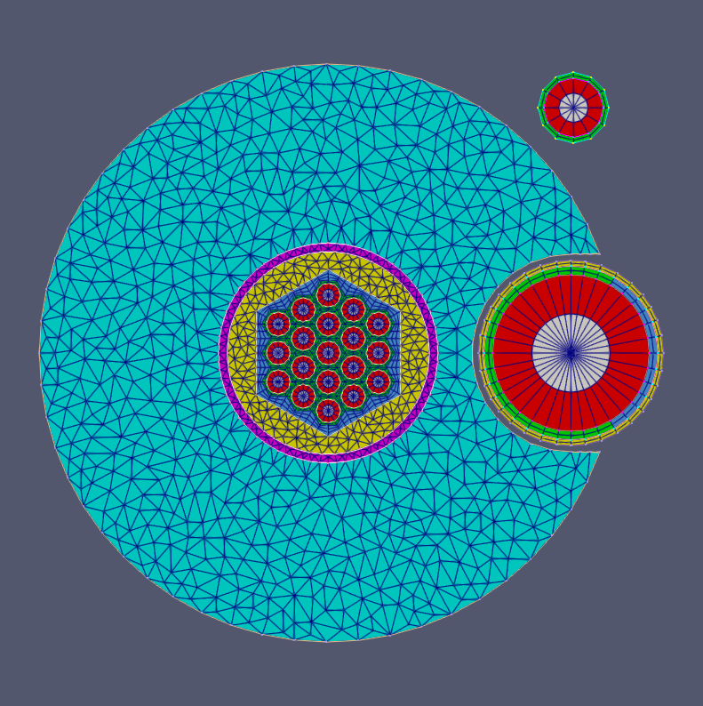
Triangulation of Odd-Shaped Regions (cont.)
The outer boundary of the dark blue zone is then generated using ParsedCurveGenerator and analytical functions. XYDelaunayGenerator is again used to fill the dark blue regions, keeping the light blue region and assembly, control drum, and small pin.
[Mesh<<<{"href": "../../../../syntax/Mesh/index.html"}>>>]
  [pcg2]
    type = ParsedCurveGenerator<<<{"description": "This ParsedCurveGenerator object is designed to generate a mesh of a curve that consists of EDGE2, EDGE3, or EDGE4 elements.", "href": "../../../../source/meshgenerators/ParsedCurveGenerator.html"}>>>
    x_formula<<<{"description": "Function expression of x(t)"}>>> = 'r*cos(t)'
    y_formula<<<{"description": "Function expression of y(t)"}>>> = 'r*sin(t)'
    section_bounding_t_values<<<{"description": "The 't' values that bound the sections of the curve. Start and end points must be included. The number of entries in 'nums_segments' should be equal to one less than the number of entries in this parameter."}>>> = '0 ${fparse 2*pi}'
    constant_names<<<{"description": "Vector of constants used in the parsed function (use this for kB etc.)"}>>> = 'pi           r'
    constant_expressions<<<{"description": "Vector of values for the constants in constant_names (can be an FParser expression)"}>>> = '${fparse pi} 140.0'
    nums_segments<<<{"description": "Numbers of segments (EDGE elements) of each section of the curve to be generated. The number of entries in this parameter should be equal to one less than the number of entries in 'section_bounding_t_values'"}>>> = '100'
    is_closed_loop<<<{"description": "Whether the curve is closed or not."}>>> = true
  []

  [xydg2]
    type = XYDelaunayGenerator<<<{"description": "Triangulates meshes within boundaries defined by input meshes.", "href": "../../../../source/meshgenerators/XYDelaunayGenerator.html"}>>>
    boundary<<<{"description": "The input MeshGenerator defining the output outer boundary and required Steiner points."}>>> = 'pcg2'
    holes<<<{"description": "The MeshGenerators that define mesh holes."}>>> = 'xydg1 cd_translate op_translate'
    add_nodes_per_boundary_segment<<<{"description": "How many more nodes to add in each outer boundary segment."}>>> = 0
    refine_boundary<<<{"description": "Whether to allow automatically refining the outer boundary."}>>> = false
    desired_area<<<{"description": "Desired (maximum) triangle area, or 0 to skip uniform refinement"}>>> = 30
    output_subdomain_name<<<{"description": "Subdomain name to set on new triangles."}>>> = xy_layer_2
    stitch_holes<<<{"description": "Whether to stitch to the mesh defining each hole."}>>> = 'true true true'
    refine_holes<<<{"description": "Whether to allow automatically refining each hole boundary."}>>> = 'false false false'
  []
[]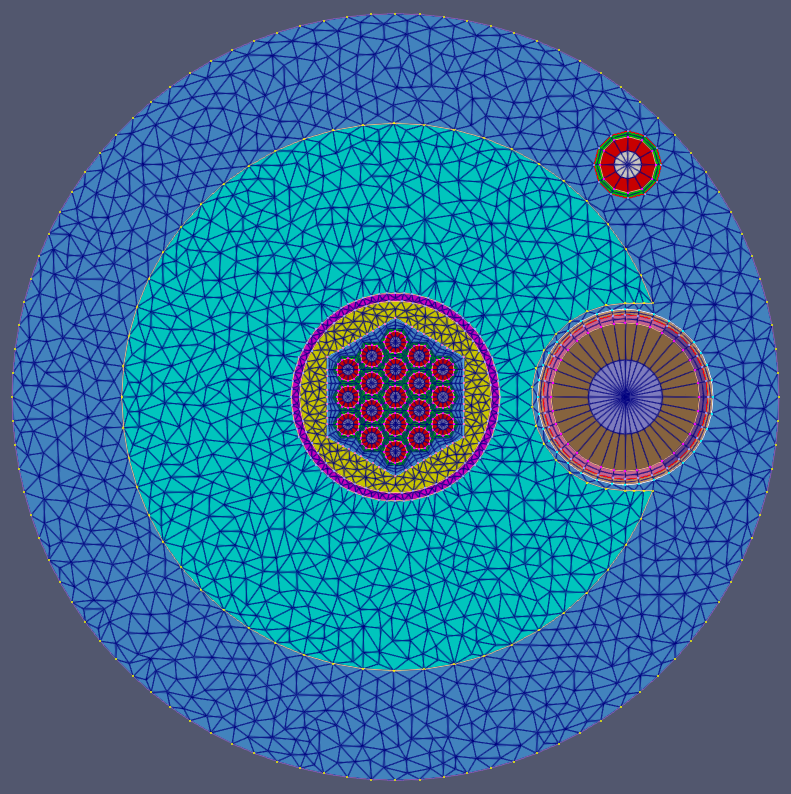
Triangulation of Odd-Shaped Regions (cont.)
Finally, a circular peripheral region is added at the end using PeripheralTriangleMeshGenerator (yellow).
[Mesh<<<{"href": "../../../../syntax/Mesh/index.html"}>>>]
  [tmg3]
    type = PeripheralTriangleMeshGenerator<<<{"description": "This PeripheralTriangleMeshGenerator object is designed to generate a triangulated mesh between a generated outer circle boundary and a provided inner mesh.", "href": "../../../../source/meshgenerators/PeripheralTriangleMeshGenerator.html"}>>>
    input<<<{"description": "The input mesh to be modified."}>>> = xydg2
    peripheral_ring_radius<<<{"description": "Radius of the peripheral ring to be added."}>>> = 150
    peripheral_ring_num_segments<<<{"description": "Number of segments of the peripheral ring."}>>> = 100
    peripheral_ring_block_name<<<{"description": "The block name assigned to the created peripheral layer."}>>> = peripheral_3
    desired_area<<<{"description": "Desired (maximum) triangle area, or 0 to skip uniform refinement"}>>> = 20
  []
[]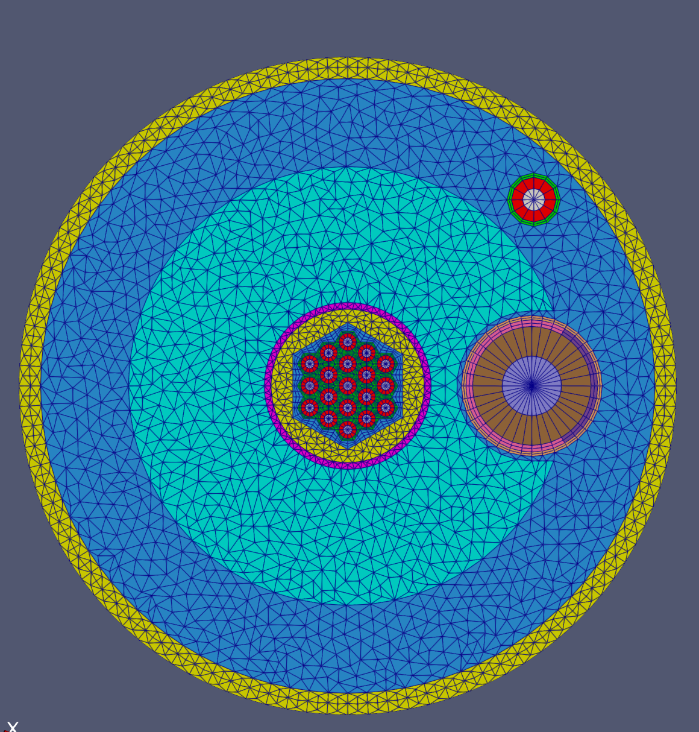
References
- James Ahrens, Berk Geveci, and Charles Law. ParaView: an end-user tool for large data visualization. In Visualization Handbook. Elesvier, 2005. URL: https://doi.org/10.1016/B978-012387582-2/50038-1.
- Christopher Matthews, Vincent Laboure, Mark DeHart, Joshua Hansel, David Andrs, Yaqi Wang, Javier Ortensi, and Richard C Martineau. Coupled multiphysics simulations of heat pipe microreactors using direwolf. Nuclear Technology, 207(7):1142–1162, 2021.
- E. R. Shemon, J. J. Grudzinski, C. H. Lee, J. W. Thomas, and Y. Q. Yu. Specification of the advanced burner test reactor multi-physics coupling demonstration problem. Technical Report ANL/NE-15/43, Argonne National Laboratory, 12 2015. URL: https://www.osti.gov/biblio/1236452, doi:10.2172/1236452.