Reactor Geometry Mesh Builder: A Contained System for Building Regular Geometries
Reactor Geometry Mesh Builder (RGMB) refers to a subset of specialized mesh generators designed specifically for simplifying the task of building reactor geometries. These mesh generators are intended to be called in a specific order and assume that pin-like structures are built into a Cartesian or hexagonal assembly lattice. These assembly lattices can be combined into a core lattice with a peripheral ring added to the core boundary. RGMB mesh generation is accomplished by calling base Reactor module mesh generators under-the-hood while exposing only the minimum number of parameters needed by the user to define the reactor geometry.
Benefits of RGMB system include:
Simplified user options for generation of reactor meshes
Minimal number of blocks associated with output mesh – one block is allocated to all quadrilateral elements and another block is used for all triangular elements
Automatic assignment of extra element integers:
pin_id,assembly_id,plane_idAssignment of region ids directly on the mesh, avoiding the need to define these map materials to mesh in the MOOSE physics application input file
The RGMB system is useful for regular 2D or extruded 3D Cartesian or hexagonal geometries. Many useful meshing options (e.g., boundary layers) are currently hidden and unavailable to the user through RGMB to keep things simple. If these options are needed for more complex geometries, the individual Reactor Module mesh generators should be used as shown in earlier sections. Additionally, control drum mesh generation support has been added for hexagonal core layouts.
RGMB consists of a few specific mesh generators which are to be called in order and detailed next.
ReactorMeshParams
ReactorMeshParams acts as a container for storing global data about the reactor geometry that needs to be retrieved at different stages of the RGMB mesh generation workflow. In particular, the union axial grid for the extruded geometry is defined here and propagated to the entire mesh upon the extrusion step.
Listing 1: Reactor Mesh Parameters example.
[Mesh<<<{"href": "../../../syntax/Mesh/index.html"}>>>]
  [rmp]
    type = ReactorMeshParams<<<{"description": "This ReactorMeshParams object acts as storage for persistent information about the reactor geometry.", "href": "../../../source/meshgenerators/ReactorMeshParams.html"}>>>
    dim<<<{"description": "The dimension of the mesh to be generated"}>>> = 3
    geom<<<{"description": "The geometry type of the reactor mesh"}>>> = "Square"
    assembly_pitch<<<{"description": "Center to center distance of assemblies"}>>> = 2.84126
    axial_regions<<<{"description": "Length of each axial region"}>>> = '1.0'
    axial_mesh_intervals<<<{"description": "Number of elements in the Z direction for each axial region"}>>> = '1'
    top_boundary_id<<<{"description": "The boundary ID to set on top boundary of the extruded mesh"}>>> = 201
    bottom_boundary_id<<<{"description": "The boundary ID to set on bottom boundary of the extruded mesh"}>>> = 202
    radial_boundary_id<<<{"description": "The boundary ID to set on the outer radial boundary of a CoreMeshGenerator object"}>>> = 200
  []
[]PinMeshGenerator
PinMeshGenerator calls PolygonConcentricCircleMeshGenerator to generate a Cartesian or hexagonal pin-like structure (pin, background, and duct)
Listing 2: RGMB Pin example.
[Mesh<<<{"href": "../../../syntax/Mesh/index.html"}>>>]
  [pin1]
    type = PinMeshGenerator<<<{"description": "This PinMeshGenerator object is designed to generate pin-like structures, with IDs, from a reactor geometry. Whether it be a square or hexagonal pin, they are divided into three substructures - the innermost radial pin regions, the single bridging background region, and the square or hexagonal ducts regions.", "href": "../../../source/meshgenerators/PinMeshGenerator.html"}>>>
    reactor_params<<<{"description": "The ReactorMeshParams MeshGenerator that is the basis for this component conformal mesh."}>>> = rmp
    pin_type<<<{"description": "The integer ID for this pin type definition"}>>> = 1
    pitch<<<{"description": "The pitch for the outermost boundary polygon"}>>> = 1.42063
    num_sectors<<<{"description": "Number of azimuthal sectors in each quadrant"}>>> = 2
    ring_radii<<<{"description": "Radii of major concentric circles of the pin. If unspecified, no pin is present."}>>> = 0.2
    duct_halfpitch<<<{"description": "Apothem of the ducts. If unspecified, no duct is present."}>>> = 0.58
    mesh_intervals<<<{"description": "The number of meshing intervals for each region starting at the center. Parameter should be size:((length(ring_radii) + length(duct_halfpitch) + 1"}>>> = '1 1 1'
    region_ids<<<{"description": "IDs for each radial and axial zone for assignment of region_id extra element id. Inner indexing is radial zones (pin/background/duct), outer indexing is axial"}>>> = '1 2 5'
    quad_center_elements<<<{"description": "Whether the center elements are quad or triangular."}>>> = true
  []
[]The final mesh will contain one block (subdomain) for quadrilateral elements and one block for triangular elements. Regions with different materials are distinguished by the region_id reporting ID rather than by subdomain ID.
"region_ids" is a 2D array parameter that sets the region_id by radial region (rows) and axial region (column). The 3D material map is stored for use after extrusion, which could happen at the pin, assembly, or core step, whichever step is final for the problem of interest.
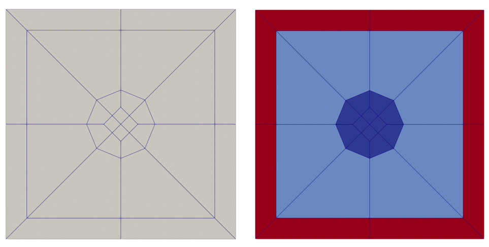
Figure 1: Example RGMB Cartesian pin cell mesh colored by subdomain_id (left) and region_id (right).
Listing 3: Example RGMB Cartesian pin cell.
[Mesh<<<{"href": "../../../syntax/Mesh/index.html"}>>>]
  [pin1]
    type = PinMeshGenerator<<<{"description": "This PinMeshGenerator object is designed to generate pin-like structures, with IDs, from a reactor geometry. Whether it be a square or hexagonal pin, they are divided into three substructures - the innermost radial pin regions, the single bridging background region, and the square or hexagonal ducts regions.", "href": "../../../source/meshgenerators/PinMeshGenerator.html"}>>>
    reactor_params<<<{"description": "The ReactorMeshParams MeshGenerator that is the basis for this component conformal mesh."}>>> = rmp
    pin_type<<<{"description": "The integer ID for this pin type definition"}>>> = 1
    pitch<<<{"description": "The pitch for the outermost boundary polygon"}>>> = 1.42063
    num_sectors<<<{"description": "Number of azimuthal sectors in each quadrant"}>>> = 2
    ring_radii<<<{"description": "Radii of major concentric circles of the pin. If unspecified, no pin is present."}>>> = 0.2
    duct_halfpitch<<<{"description": "Apothem of the ducts. If unspecified, no duct is present."}>>> = 0.58
    mesh_intervals<<<{"description": "The number of meshing intervals for each region starting at the center. Parameter should be size:((length(ring_radii) + length(duct_halfpitch) + 1"}>>> = '1 1 1'
    region_ids<<<{"description": "IDs for each radial and axial zone for assignment of region_id extra element id. Inner indexing is radial zones (pin/background/duct), outer indexing is axial"}>>> = '1 2 5'
    quad_center_elements<<<{"description": "Whether the center elements are quad or triangular."}>>> = true
  []
[]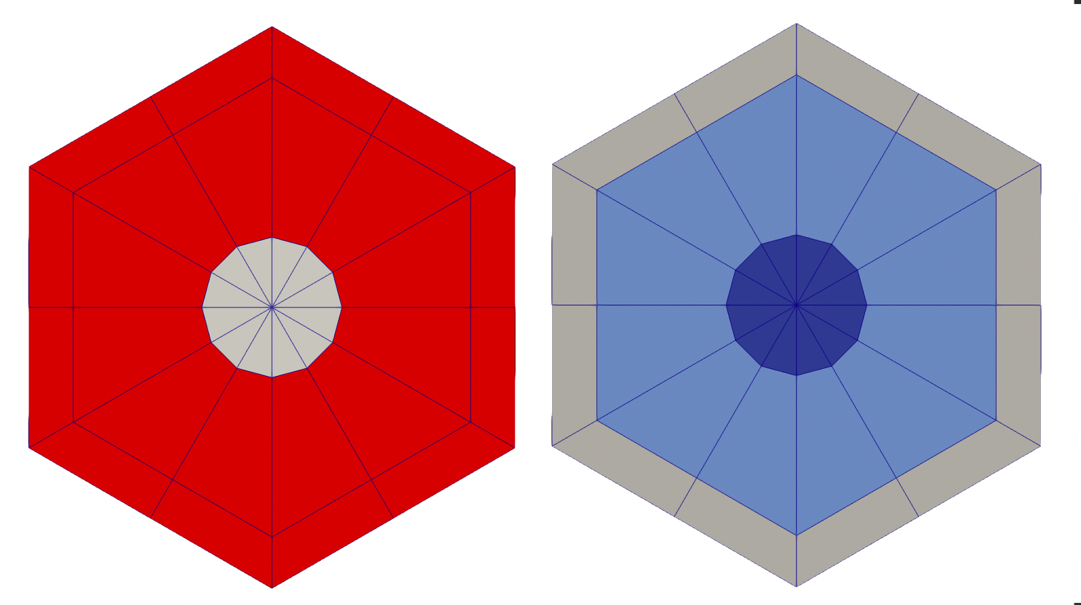
Figure 2: Example RGMB hexagonal pin cell mesh colored by subdomain_id (left) and region_id (right).
Listing 4: Example RGMB hexagonal pin cell.
[Mesh<<<{"href": "../../../syntax/Mesh/index.html"}>>>]
  [pin1]
    type = PinMeshGenerator<<<{"description": "This PinMeshGenerator object is designed to generate pin-like structures, with IDs, from a reactor geometry. Whether it be a square or hexagonal pin, they are divided into three substructures - the innermost radial pin regions, the single bridging background region, and the square or hexagonal ducts regions.", "href": "../../../source/meshgenerators/PinMeshGenerator.html"}>>>
    reactor_params<<<{"description": "The ReactorMeshParams MeshGenerator that is the basis for this component conformal mesh."}>>> = rmp
    pin_type<<<{"description": "The integer ID for this pin type definition"}>>> = 1
    pitch<<<{"description": "The pitch for the outermost boundary polygon"}>>> = 1.42063
    num_sectors<<<{"description": "Number of azimuthal sectors in each quadrant"}>>> = 2
    ring_radii<<<{"description": "Radii of major concentric circles of the pin. If unspecified, no pin is present."}>>> = 0.2
    duct_halfpitch<<<{"description": "Apothem of the ducts. If unspecified, no duct is present."}>>> = 0.58
    mesh_intervals<<<{"description": "The number of meshing intervals for each region starting at the center. Parameter should be size:((length(ring_radii) + length(duct_halfpitch) + 1"}>>> = '1 1 1'
    region_ids<<<{"description": "IDs for each radial and axial zone for assignment of region_id extra element id. Inner indexing is radial zones (pin/background/duct), outer indexing is axial"}>>> = '1 2 3'
    quad_center_elements<<<{"description": "Whether the center elements are quad or triangular."}>>> = false
  []
[]AssemblyMeshGenerator
AssemblyMeshGenerator calls PatternedHexMeshGenerator or PatternedCartesianMeshGenerator to generate a Cartesian or hexagonal lattice of pin-like structures. Cartesian and hexagonal examples follow.
RGMB Cartesian Assembly Example
Tips:
Elements belonging to a unique pin cell will be automatically provided a unique
pin_idDucts for Cartesian assemblies are not currently supported
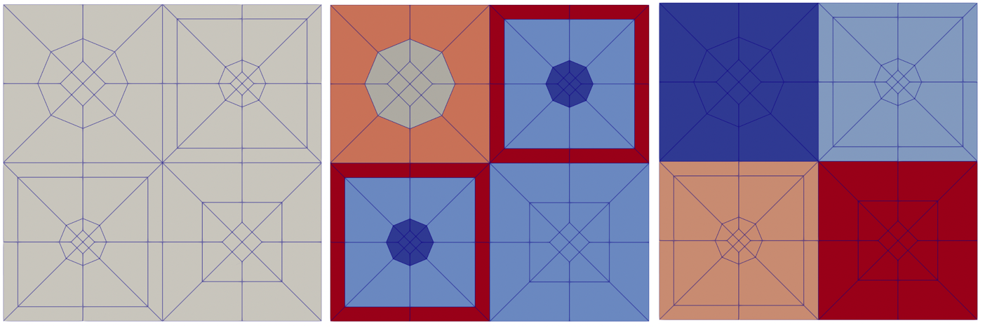
Figure 3: Cartesian assembly colored by subdomain_id (left), region_id (middle), and pin_id (right). Subdomain ids categorize elements as belonging to different subdomains (blocks), region ids categorize elements belonging to different regions (material zones), and pin ids categorize elements belonging to different pin cells.
Listing 5: Example RGMB Cartesian assembly.
[Mesh<<<{"href": "../../../syntax/Mesh/index.html"}>>>]
  [assembly1]
    type = AssemblyMeshGenerator<<<{"description": "This AssemblyMeshGenerator object is designed to generate assembly-like structures, with IDs, from a reactor geometry. The assembly-like structures must consist of a full pattern of equal sized pins from PinMeshGenerator. A hexagonal assembly will be placed inside of a bounding hexagon consisting of a background region and, optionally, duct regions.", "href": "../../../source/meshgenerators/AssemblyMeshGenerator.html"}>>>
    assembly_type<<<{"description": "The integer ID for this assembly type definition"}>>> = 2
    inputs<<<{"description": "The PinMeshGenerators that form the components of the assembly."}>>> = 'pin3 pin1 pin2'
    pattern<<<{"description": "A double-indexed array starting with the upper-left corner where the indexrepresents the layout of input pins in the assembly lattice."}>>> = '0 1;
               1 2'
  []
[]RGMB Hexagonal Assembly Example
AssemblyMeshGenerator calls PatternedHexMeshGenerator or PatternedMeshGenerator to generate a Cartesian or hexagonal lattice of pin-like structures.
Tips:
Hexagonal ducts and background coolant region can be added to hexagonal assemblies. The region IDs for the duct and background regions are set by the
duct_region_idsandbackground_region_idparameters.Don't want explicitly defined pins in your assembly? See Reactor Geometry Mesh Builder Example: Conversion of Heterogeneous to Homogeneous Sodium-Cooled Fast Reactor Core Mesh (ABTR) for how to define homogenized assemblies with AssemblyMeshGenerator.
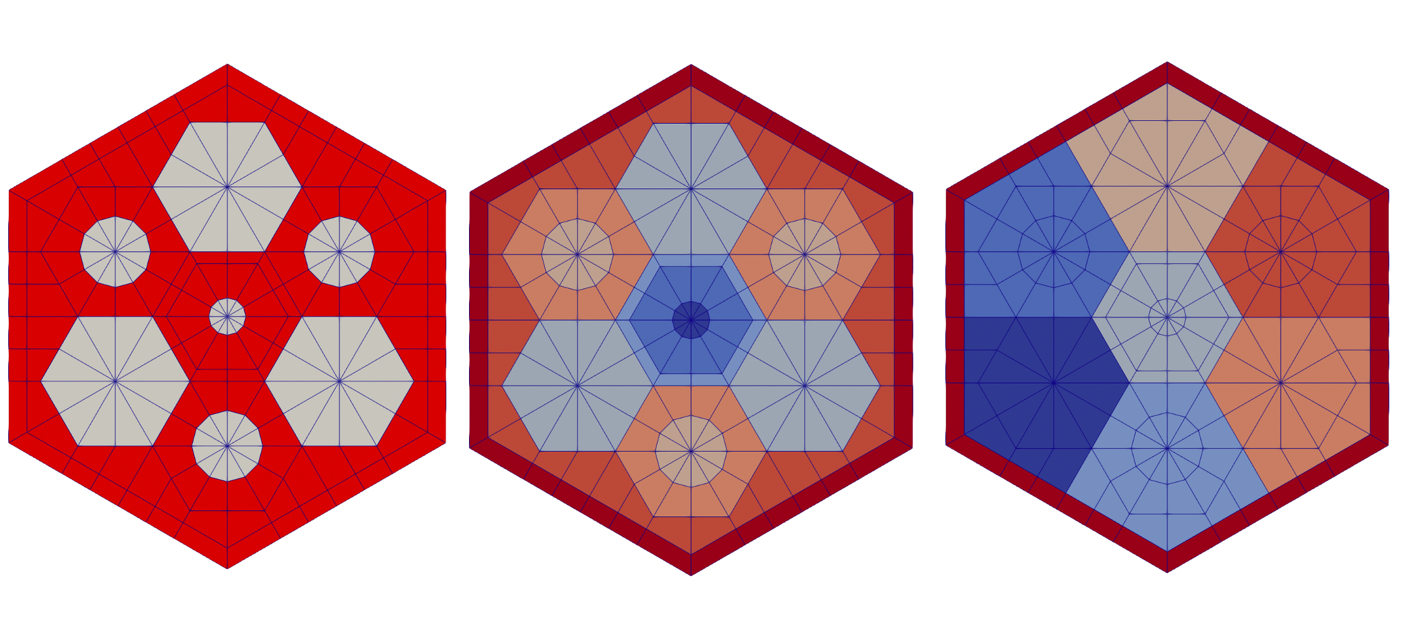
Figure 4: Hexagonal assembly colored by subdomain_id (left), region_id (middle), and pin_id (right). Subdomain ids categorize elements as belonging to different subdomains (blocks), region ids categorize elements belonging to different regions (material zones), and pin ids categorize elements belonging to different pin cells.
Listing 6: Example RGMB hexagonal assembly.
[Mesh<<<{"href": "../../../syntax/Mesh/index.html"}>>>]
  [assembly1]
    type = AssemblyMeshGenerator<<<{"description": "This AssemblyMeshGenerator object is designed to generate assembly-like structures, with IDs, from a reactor geometry. The assembly-like structures must consist of a full pattern of equal sized pins from PinMeshGenerator. A hexagonal assembly will be placed inside of a bounding hexagon consisting of a background region and, optionally, duct regions.", "href": "../../../source/meshgenerators/AssemblyMeshGenerator.html"}>>>
    assembly_type<<<{"description": "The integer ID for this assembly type definition"}>>> = 1
    inputs<<<{"description": "The PinMeshGenerators that form the components of the assembly."}>>> = 'pin1 pin2 pin3'
    pattern<<<{"description": "A double-indexed array starting with the upper-left corner where the indexrepresents the layout of input pins in the assembly lattice."}>>> = '1 2;
              2 0 1;
               1 2'
    background_intervals<<<{"description": "Radial intervals in the assembly peripheral region."}>>> = 1
    background_region_id<<<{"description": "The region id for the background area between the pins and the ducts to set region_id extra-element integer"}>>> = 7
    duct_intervals<<<{"description": "Number of meshing intervals in each enclosing duct."}>>> = 1
    duct_halfpitch<<<{"description": "Distance(s) from center to duct(s) inner boundaries."}>>> = 2.2
    duct_region_ids<<<{"description": "The region id for the ducts from innermost to outermost, to set region_id extra-element integer."}>>> = 8
  []
[]CoreMeshGenerator
CoreMeshGenerator calls PatternedHexMeshGenerator or PatternedMeshGenerator to generate a Cartesian or hexagonal lattice of assembly-like structures.
Defining "dummy_assembly_name" and using it in inputs defines a dummy assembly in the core.
Cartesian Core Example
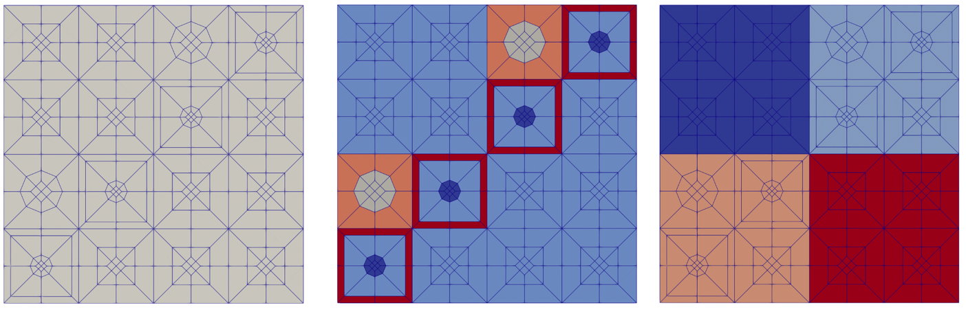
Figure 5: Cartesian core colored by subdomain_id (left), region_id (middle), and assembly_id (right).
Listing 7: Example RGMB Cartesian core.
[Mesh<<<{"href": "../../../syntax/Mesh/index.html"}>>>]
  [rgmb_core]
    type = CoreMeshGenerator<<<{"description": "This CoreMeshGenerator object is designed to generate a core-like structure, with IDs, from a reactor geometry. The core-like structure consists of a pattern of assembly-like structures generated with AssemblyMeshGenerator and/or ControlDrumMeshGenerator and is permitted to have \"empty\" locations. The size and spacing of the assembly-like structures is defined, and enforced by declaration in the ReactorMeshParams.", "href": "../../../source/meshgenerators/CoreMeshGenerator.html"}>>>
    inputs<<<{"description": "The AssemblyMeshGenerator and ControlDrumMeshGenerator objects that form the components of the assembly."}>>> = 'assembly1 assembly2'
    pattern<<<{"description": "A double-indexed array starting with the upper-left corner where the indexrepresents the layout of input assemblies in the core lattice."}>>> = '1 0;
               0 1'
    extrude<<<{"description": "Determines if this is the final step in the geometry construction and extrudes the 2D geometry to 3D. If this is true then this mesh cannot be used in further mesh building in the Reactor workflow"}>>> = true
  []
[]Hexagonal Core Example

Figure 6: Hexagonal core colored by subdomain_id (left), region_id (middle), and assembly_id (right).
Listing 8: Example RGMB Hexagonal core.
[Mesh<<<{"href": "../../../syntax/Mesh/index.html"}>>>]
  [rgmb_core]
    type = CoreMeshGenerator<<<{"description": "This CoreMeshGenerator object is designed to generate a core-like structure, with IDs, from a reactor geometry. The core-like structure consists of a pattern of assembly-like structures generated with AssemblyMeshGenerator and/or ControlDrumMeshGenerator and is permitted to have \"empty\" locations. The size and spacing of the assembly-like structures is defined, and enforced by declaration in the ReactorMeshParams.", "href": "../../../source/meshgenerators/CoreMeshGenerator.html"}>>>
    inputs<<<{"description": "The AssemblyMeshGenerator and ControlDrumMeshGenerator objects that form the components of the assembly."}>>> = 'assembly1 assembly2 empty'
    dummy_assembly_name<<<{"description": "The place holder name in \"inputs\" that indicates an empty position."}>>> = empty
    pattern<<<{"description": "A double-indexed array starting with the upper-left corner where the indexrepresents the layout of input assemblies in the core lattice."}>>> = '2 1;
              1 0 2;
               2 1'
    extrude<<<{"description": "Determines if this is the final step in the geometry construction and extrudes the 2D geometry to 3D. If this is true then this mesh cannot be used in further mesh building in the Reactor workflow"}>>> = true
  []
[]Flexible Assembly Stitching
By default, CoreMeshGenerator does not consider the location of nodes at the boundary of assemblies when stitching the core lattice. For dissimilar assemblies, this can lead to hanging nodes at the assembly interface. The following scenarios can cause hanging nodes in the output core mesh:
Two assemblies have the same constituent pin geometry but vary in total number of pins in the pin lattice
Two assemblies have the same pin lattice structure and geometry, but the constituent pins of each assembly are subdivided into a different number of sectors per side.
One assembly is defined as a heterogeneous mesh (contains one or more pins), and the other assembly is homogenized.
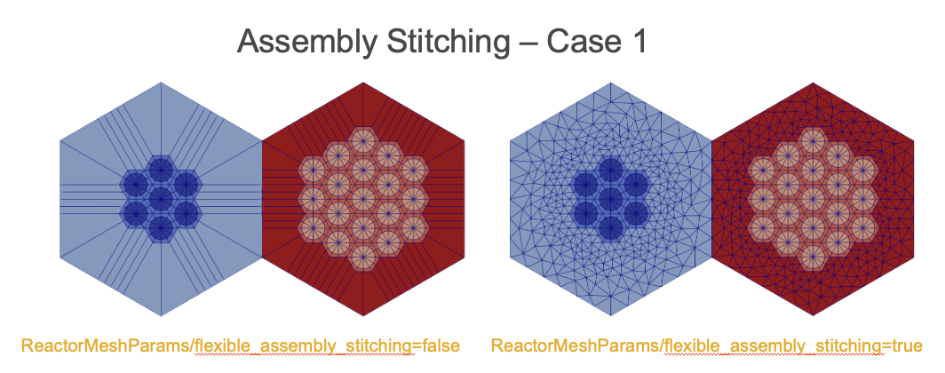
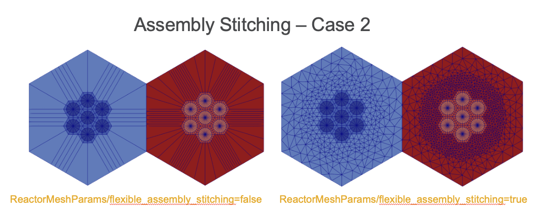
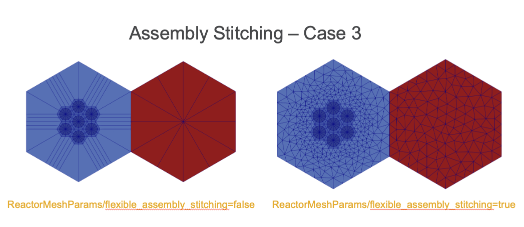
The parameter "flexible_assembly_stitching" in ReactorMeshParams can be set to true to enable flexible assembly stitching, where the outermost radial layer is deleted and re-triangulated in order to ensure the same number of nodes on either side of the assembly interface. The optional parameter "num_sectors_at_flexible_boundary" defines how many sectors should be defined at the assembly interface.
ControlDrumMeshGenerator
ControlDrumMeshGenerator calls AdvancedConcentricCircleGenerator and FlexiblePatternGenerator to generate control drum structures that can be stitched directly into a hexagonal core lattice. This mesh generator supports automatic region ID assignments as well as creation of an explicit drum pad region if desired.
Listing 9: RGMB Control drum example with no explicit pad region
[Mesh<<<{"href": "../../../syntax/Mesh/index.html"}>>>]
  [drum_nopad]
    type = ControlDrumMeshGenerator<<<{"description": "This ControlDrumMeshGenerator object is designed to generate drum-like structures, with IDs, from a reactor geometry. These structures can be used directly within CoreMeshGenerator to stitchcontrol drums into a core lattice alongside AssemblyMeshGenerator structures", "href": "../../../source/meshgenerators/ControlDrumMeshGenerator.html"}>>>
    reactor_params<<<{"description": "The ReactorMeshParams MeshGenerator that is the basis for this component mesh."}>>> = rmp
    assembly_type<<<{"description": "The assembly type integer ID to use for this control drum definition. This parameter should be uniquely defined for each ControlDrumMeshGenerator and AssemblyMeshGenerator structure in the RGMB workflow."}>>> = 3
    drum_inner_radius<<<{"description": "Inner radius of drum region"}>>> = 1.0
    drum_outer_radius<<<{"description": "Outer radius of drum region"}>>> = 1.5
    num_azimuthal_sectors<<<{"description": "Number of azimuthal sectors to sub-divide the drum region into"}>>> = 36
    drum_inner_intervals<<<{"description": "Number of radial mesh intervals in region up to inner drum radius"}>>> = 10

    region_ids<<<{"description": "IDs for each radial and axial zone for assignment of region_id extra element id. Inner indexing is radial zones (drum inner/drum/drum outer), outer indexing is axial"}>>> = '6 7 6'
  []
[]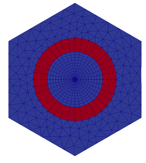
Figure 7: Example RGMB hexagonal control drum with no explicit pad region.
Listing 10: RGMB Control drum example with no explicit pad region
[Mesh<<<{"href": "../../../syntax/Mesh/index.html"}>>>]
  [drum_pad]
    type = ControlDrumMeshGenerator<<<{"description": "This ControlDrumMeshGenerator object is designed to generate drum-like structures, with IDs, from a reactor geometry. These structures can be used directly within CoreMeshGenerator to stitchcontrol drums into a core lattice alongside AssemblyMeshGenerator structures", "href": "../../../source/meshgenerators/ControlDrumMeshGenerator.html"}>>>
    reactor_params<<<{"description": "The ReactorMeshParams MeshGenerator that is the basis for this component mesh."}>>> = rmp
    assembly_type<<<{"description": "The assembly type integer ID to use for this control drum definition. This parameter should be uniquely defined for each ControlDrumMeshGenerator and AssemblyMeshGenerator structure in the RGMB workflow."}>>> = 4
    drum_inner_radius<<<{"description": "Inner radius of drum region"}>>> = 1.0
    drum_outer_radius<<<{"description": "Outer radius of drum region"}>>> = 1.5
    num_azimuthal_sectors<<<{"description": "Number of azimuthal sectors to sub-divide the drum region into"}>>> = 36
    drum_inner_intervals<<<{"description": "Number of radial mesh intervals in region up to inner drum radius"}>>> = 10

    pad_start_angle<<<{"description": "Starting angle of drum pad region"}>>> = 90
    pad_end_angle<<<{"description": "Ending angle of drum pad region"}>>> = 180
    region_ids<<<{"description": "IDs for each radial and axial zone for assignment of region_id extra element id. Inner indexing is radial zones (drum inner/drum/drum outer), outer indexing is axial"}>>> = '8 9 10 8'
  []
[]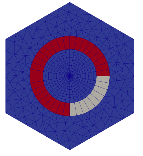
Figure 8: Example RGMB hexagonal control drum with explicit pad region.
The drum angle starts in the positive y-direction and increases in a clockwise direction. In addition, in order to use ControlDrumMeshGenerator, "flexible_assembly_stitching" in ReactorMeshParams needs to be set to true. This ensures that control drum structures can be stitched in a core lattice with other assemblies without hanging nodes.
CoreMeshGenerator with ControlDrumMeshGenerator
Use of ControlDrumMeshGenerator allows for drum structures to be stitched directly into the lattice defined in CoreMeshGenerator. Setting "flexible_assembly_stitching" in ReactorMeshParams to true ensures that all assembly structures get stitched together without any hanging nodes.
Listing 11: Hexagonal core with control drums stitched in lattice
[Mesh<<<{"href": "../../../syntax/Mesh/index.html"}>>>]
  [rgmb_core]
    type = CoreMeshGenerator<<<{"description": "This CoreMeshGenerator object is designed to generate a core-like structure, with IDs, from a reactor geometry. The core-like structure consists of a pattern of assembly-like structures generated with AssemblyMeshGenerator and/or ControlDrumMeshGenerator and is permitted to have \"empty\" locations. The size and spacing of the assembly-like structures is defined, and enforced by declaration in the ReactorMeshParams.", "href": "../../../source/meshgenerators/CoreMeshGenerator.html"}>>>
    inputs<<<{"description": "The AssemblyMeshGenerator and ControlDrumMeshGenerator objects that form the components of the assembly."}>>> = 'assembly1 drum_pad drum_nopad'
    dummy_assembly_name<<<{"description": "The place holder name in \"inputs\" that indicates an empty position."}>>> = empty
    pattern<<<{"description": "A double-indexed array starting with the upper-left corner where the indexrepresents the layout of input assemblies in the core lattice."}>>> = '2 1;
              1 0 2;
               2 1'
    extrude<<<{"description": "Determines if this is the final step in the geometry construction and extrudes the 2D geometry to 3D. If this is true then this mesh cannot be used in further mesh building in the Reactor workflow"}>>> = true
  []
[]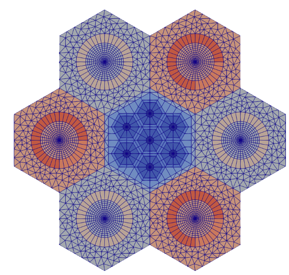
Figure 9: Hexagonal core with control drums stitched in lattive
CoreMeshGenerator with Peripheral Ring
A core periphery region can be added utilizing either the PeripheralRingMeshGenerator or the PeripheralTriangleMeshGenerator.
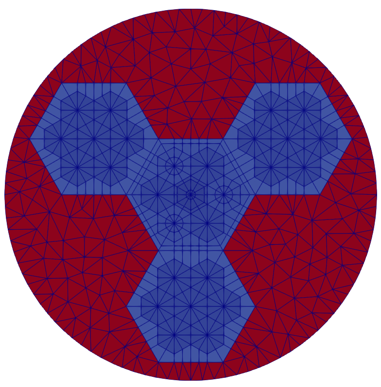
Figure 10: Hexagonal core with core periphery meshed.
Listing 12: Example RGMB Hexagonal core with periphery.
[Mesh<<<{"href": "../../../syntax/Mesh/index.html"}>>>]
  [rgmb_core]
    type = CoreMeshGenerator<<<{"description": "This CoreMeshGenerator object is designed to generate a core-like structure, with IDs, from a reactor geometry. The core-like structure consists of a pattern of assembly-like structures generated with AssemblyMeshGenerator and/or ControlDrumMeshGenerator and is permitted to have \"empty\" locations. The size and spacing of the assembly-like structures is defined, and enforced by declaration in the ReactorMeshParams.", "href": "../../../source/meshgenerators/CoreMeshGenerator.html"}>>>
    inputs<<<{"description": "The AssemblyMeshGenerator and ControlDrumMeshGenerator objects that form the components of the assembly."}>>> = 'assembly1 assembly2 empty'
    dummy_assembly_name<<<{"description": "The place holder name in \"inputs\" that indicates an empty position."}>>> = empty
    pattern<<<{"description": "A double-indexed array starting with the upper-left corner where the indexrepresents the layout of input assemblies in the core lattice."}>>> = '2 1;
              1 0 2;
               2 1'
    extrude<<<{"description": "Determines if this is the final step in the geometry construction and extrudes the 2D geometry to 3D. If this is true then this mesh cannot be used in further mesh building in the Reactor workflow"}>>> = false

    mesh_periphery<<<{"description": "Determines if the core periphery should be meshed."}>>> = true
    periphery_generator<<<{"description": "The meshgenerator to use when meshing the core boundary."}>>> = triangle
    periphery_region_id<<<{"description": "ID for periphery zone for assignment of region_id extra element id."}>>> = 100
    outer_circle_radius<<<{"description": "Radius of outer circle boundary."}>>> = 8
    outer_circle_num_segments<<<{"description": "Number of radial segments to subdivide outer circle boundary."}>>> = 100
    desired_area<<<{"description": "Desired (maximum) triangle area, or 0 to skip uniform refinement"}>>> = 0.5
  []
[]Default Block and External Boundary Names
An RGMB case can terminate at the pin, assembly, or core "level". Pins and assemblies always have a "type" assigned (a numeric integer specified as "pin_type" for pins and "assembly_type" for assemblies), whereas cores do not. The "level" and "type" are used in the naming schemes for the blocks and outer boundary as follows:
The default block names in the final mesh are
RGMB_(level)(type)andRGMB_(level)(type)_TRI(if triangular elements are present). For example,RGMB_PIN1andRMGB_PIN1_TRI, orRGMB_ASSEMBLY1andRGMB_ASSEMBLY1_TRI, orRGMB_COREandRGMB_CORE_TRI, for workflows ending at the pin, assembly or core level, respectively.The default outer boundary names in the radial dimension are
outer_(level)_(type). For example, for workflows ending at the pin, assembly or core level respectively, the outer boundary names areouter_pin_1,outer_assembly_1andouter_core.If the problem is extruded in the axial dimension, the
topandbottomboundaries also exist.For users that require a block name that is linked to the region ID of the element, ReactorMeshParams/"region_id_as_block_name" can be set to true to accomplish this. In this case, the block name will be set as
RGMB_(level)(type)_REG(region_id), where "region_id" refers to the region ID extra element integer the element. For triangular elements, the suffix "_TRI" will also be added.