GCMR Core Thermal Model
Point of Contact: Lise Charlot (lise.charlot.at.inl.gov)
Model link: GCMR Core Thermal Model
Mesh file
A 3-D mesh for the core is generated using the MOOSE Reactor module. Details of the mesh for an assembly is shown in Figure 1.
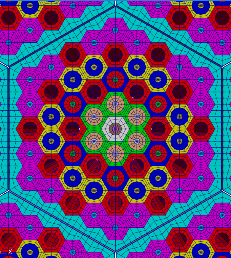
Figure 1: Details of the core 3D mesh
First, the pincell for the moderator, fuel and coolant channels are created. Several rings are used for the fuel channels to be able to prescribe a non-uniform power density in the assembly.
  [moderator_pincell]
    type = PolygonConcentricCircleMeshGenerator
    num_sides = 6 # must be six to use hex pattern
    num_sectors_per_side = '2 2 2 2 2 2 '
    background_intervals = 2.
    background_block_ids = '1'
    polygon_size = ${pincell_apothem}
    polygon_size_style = 'apothem'
    ring_radii = '${fparse pincell_apothem / 2 }'
    ring_intervals = '2'
    ring_block_ids = '103 101' # 103 is tri mesh
    preserve_volumes = on
    quad_center_elements = false
  []
  [coolant_pincell]
    type = PolygonConcentricCircleMeshGenerator
    num_sides = 6 # must be six to use hex pattern
    num_sectors_per_side = '2 2 2 2 2 2 '
    background_intervals = 2.
    background_block_ids = '2'
    polygon_size = ${pincell_apothem}
    polygon_size_style = 'apothem'
    ring_radii = '${radius_coolant}'
    ring_intervals = '2'
    ring_block_ids = '203 201' # 203 is tri mesh
    preserve_volumes = on
    quad_center_elements = false
  []
  [fuel_pincell_ring1]
    type = PolygonConcentricCircleMeshGenerator
    num_sides = 6 # must be six to use hex pattern
    num_sectors_per_side = '2 2 2 2 2 2 '
    background_intervals = 2.
    background_block_ids = '3'
    polygon_size = ${pincell_apothem}
    polygon_size_style = 'apothem'
    ring_radii = '${radius_fuel}'
    ring_intervals = '3'
    ring_block_ids = '303 301' # 303 is tri mesh
    preserve_volumes = on
    quad_center_elements = false
[]Using multiple pincells, the assembly pattern is created using the PatternedHexMeshGenerator. The outermost duct block represents the bypass and will be deleted.
[Mesh]
  [fuel_assembly]
    type = PatternedHexMeshGenerator
    inputs = 'coolant_pincell fuel_pincell_ring1 fuel_pincell_ring2 fuel_pincell_ring3 fuel_pincell_ring4 moderator_pincell'
    # Pattern ID     0                 1                  2                  3                  4                   5
    hexagon_size = ${assembly_apothem}
    background_block_id = 10
    background_intervals = 2
    duct_block_ids = '12 11'
    duct_sizes_style = apothem
    duct_sizes = '${fparse assembly_apothem - 0.0008} ${fparse assembly_apothem - 0.0005}'
    duct_intervals = '3 1'
    pattern = '4 4 0 4 4;
              4 0 3 3 0 4;
             0 3 2 0 2 3 0;
            4 3 0 1 1 0 3 4;
           4 0 2 1 5 1 2 0 4;
            4 3 0 1 1 0 3 4;
             0 3 2 0 2 3 0;
              4 0 3 3 0 4;
               4 4 0 4 4'
  []
[]The assembly mesh is then used to create the core layout.
[Mesh]
  [core]
    type = PatternedHexMeshGenerator
    inputs = 'fuel_assembly'
    pattern_boundary = none
    generate_core_metadata = true
    pattern = '0 0 0 0 0;
              0 0 0 0 0 0;
             0 0 0 0 0 0 0;
            0 0 0 0 0 0 0 0;
           0 0 0 0 0 0 0 0 0;
            0 0 0 0 0 0 0 0;
             0 0 0 0 0 0 0;
              0 0 0 0 0 0;
               0 0 0 0 0'
  []
[]The reflector is added using the PeripheralRingMeshGenerator mesh generator.
[Mesh]
  [reflector]
    type = PeripheralRingMeshGenerator
    input = core
    peripheral_layer_num = 2
    peripheral_ring_radius = 0.9
    input_mesh_external_boundary = 10000
    peripheral_ring_block_id = 250
    peripheral_ring_block_name = reflector
  []
[]This 2-D mesh is then extruded to create the 3D mesh.
[Mesh]
  [extrude]
    type = AdvancedExtruderGenerator
    input = reflector
    heights = '2'
    num_layers = '10'

    direction = '0 0 1'
    top_boundary = 2000
    bottom_boundary = 3000
  []
[]A sideset for the coolant boundary is created and the coolant channels removed.
  [add_coolant_boundary]
    type = SideSetsBetweenSubdomainsGenerator
    input = extrude
    primary_block = '2'
    paired_block = '201'
    new_boundary = coolant_boundary
  []

  [fuel_assembly_final]
    type = BlockDeletionGenerator
    block = '201 203'
    input = add_coolant_boundary
[]A sideset for the bypass boundary is created and the bypass block is removed.
  [add_bypass_boundary]
    type = SideSetsBetweenSubdomainsGenerator
    input = fuel_assembly_final
    primary_block = '12'
    paired_block = '11'
    new_boundary = bypass_boundary
  []
  [add_bypass_boundary_out]
    type = SideSetsBetweenSubdomainsGenerator
    input = add_bypass_boundary
    primary_block = '250'
    paired_block = '11'
    new_boundary = bypass_boundary
  []
  [remove_bypass]
    type = BlockDeletionGenerator
    block = '11'
    input = add_bypass_boundary_out
[]The mesh is then rotated to match the subchannel mesh orientation.
[Mesh]
  [rotate]
    type = TransformGenerator
    input = remove_bypass
    transform = ROTATE
    vector_value = '0 0 90'
  []
[]This mesh is used for the heat conduction problem. The coolant channels and the bypass flow have their own meshes generated internally.
Heat Conduction Model
The heat conduction input file solves for the temperature in the fuel channels, moderator and reflector. The material properties for each block are defined depending on their composition using the HeatConductionMaterial and Density material blocks.
A spatially variable power density is imposed in the fuel rods. This is done using several functions and assigning them to the power_density AuxVariable. The heat source is then applied using a CoupledForce kernel.
[Kernels]
  [heat_source_fuel]
    type = CoupledForce
    variable = T
    block = '301 303 401 403 501 503 601 603'
    v = power_density
  []
[]The coupling to the helium flow in the cooling channels and in the bypass between the assemblies is performed through convective boundary conditions. AuxVariables for the heat transfer coefficient and bulk temperatures in the coolant channels and in the bypass are created and used in the boundary condition blocks. The value of these variables will be assigned by the Transfers system.
  [cooling_channels]
    type = CoupledConvectiveHeatFluxBC
    boundary = coolant_boundary
    T_infinity = T_fluid
    htc = htc
    variable = T
  []
  [bypass_conv]
    type = CoupledConvectiveHeatFluxBC
    boundary = bypass_boundary
    T_infinity = T_bypass
    htc = htc_bypass
    variable = T
[]In addition, a convective boundary condition is assigned to the outer surface to model the heat losses through the vessel.
[BCs]
  [outer_to_env]
    type = CoupledConvectiveHeatFluxBC
    boundary = 10000
    T_infinity = 800
    htc = 10
    variable = T
  []
[]Bypass flow Model
The bypass flow is modeled using Pronghorn-SC. It includes a specific problem for inter-assembly subchannels in an hexagonal pattern.
The tri-inter wrapper model has not been validated for gases. This model has been developed is for capability demonstration purposes only.
The mesh is defined using the TriInterWrapperMesh with parameters consistent with the 3D mesh used for the heat conduction problem.
[TriInterWrapperMesh]
  [sub_channel]
    type = TriInterWrapperMeshGenerator
    nrings = ${n_rings}
    n_cells = 50
    flat_to_flat = '${fparse 2 * assembly_apothem - 0.001}'
    heated_length = 2.0
    assembly_pitch = '${fparse 2 * assembly_apothem}'
    side_bypass = 0.001
    tight_side_bypass = true
  []
[]The helium fluid properties are defined using an ideal gas with the following parameters:
[FluidProperties]
  [helium]
    type = IdealGasFluidProperties
    molar_mass = 4e-3
    gamma = 1.67
    k = ${k}
    mu = ${mu}
  []
[]The flow area and wet perimeter of the subchannels are defined as AuxVariables. They are initialized using the TriInterWrapperFlowAreaIC and TriInterWrapperWettedPerimIC objects to be consistent with the mesh.
The heat transferred from the moderator block is applied using the linear heat rate AuxVariable q_prime. It is defined using a ParsedAux AuxKernel using the wet perimeter (which is equal to the heated perimeter in this case), and the flux transferred from the heat conduction problem. The value of the linear heat rate is bounded to improve the convergence of the fixed point algorithm.
[AuxKernels]
  [q_prime_aux]
    type = ParsedAux
    coupled_variables = 'w_perim flux'
    variable = q_prime
    expression = 'min(max(-10000, w_perim*flux), 30000)'
    execute_on = 'INITIAL TIMESTEP_BEGIN'
  []
[]The heat transfer coefficient to be transferred to the heat conduction problem is calculated using ParsedAux AuxKernel. It is set here to a constant value, but a more complex correlation such as Dittus-Boelter could be implemented. This approach was not chosen for this case because it was significantly increasing the number of the fixed point iterations of the multiphysics coupling.
The solver and flow model are set using the LiquidMetalInterWrapper1PhaseProblem.
[SubChannel]
  type = TriInterWrapper1PhaseProblem
  fp = helium
  n_blocks = 1
  beta = 0.1
  P_out = ${P_out}
  CT = 1.0
  compute_density = true
  compute_viscosity = true
  compute_power = true
  P_tol = 1.0e-6
  T_tol = 1.0e-6
  implicit = false
  segregated = true
  staggered_pressure = true
  T_maxit = 20
  monolithic_thermal = false
[]Note that P_out is set to the outlet pressure and the AuxVariable P is initialized to zero as P is the pressure difference with the outlet pressure. The value P+P_out is used to calculate the fluid properties.
Thermal-hydraulic model of the coolant channels
The MOOSE thermal-hydraulics module (THM) is used to mode the response of the coolant channels. The input file represents a single channel that will be replicated and translated through the MultiApp system.
The helium fluid properties are defined using an ideal gas with the following parameters:
[FluidProperties]
  [helium]
    type = IdealGasFluidProperties
    molar_mass = 4e-3
    gamma = 1.67
    k = 0.2556
    mu = 3.22639e-5
  []
[]The friction factor and heat transfer coefficient are defined using the default correlations of the Closures1PhaseTHM closures sets which are the Churchill equation for the friction factor and the Dittus Boelter correlation for the heat transfer coefficient.
[Closures]
  [thm]
    type = Closures1PhaseTHM
  []
[]The channel is defined using a FlowChannel1Phase component and the geometry parameters of a single coolant channel.
The fluid temperature and velocity are prescribed at the channel inlet using a InletVelocityTemperature1Phase component. The outlet pressure is prescribed using a Outlet1Phase component.
A convective boundary condition is applied on the channel wall using aHeatTransferFromExternalAppTemperature1Phase component. It will use the T_wall AuxVariable, the fluid bulk temperature, and the heat transfer coefficient generated by the closure set to compute the heat transferred to the channel. The value of T_wall will be transferred from the 3D heat conduction problem in the core.
[Components]
  [inlet]
    type = InletVelocityTemperature1Phase
    vel = 15
    T = ${T_in}
    input = channel:in
  []
  [channel]
    type = FlowChannel1Phase
    position = '0 0 0'
    orientation = '0 0 1'
    length = ${length_channel}
    A = ${A_channel}
    n_elems = ${channel_n_elems}
    D_h = '${fparse 2 * radius_coolant}'
  []
  [outlet]
    type = Outlet1Phase
    p = ${p_out}
    input = channel:out
  []
  [ht]
    type = HeatTransferFromExternalAppTemperature1Phase
    flow_channel = channel
    P_hf = ${P_hf_channel}
    initial_T_wall = 1200
  []
[]The Steady Executioner is used. The initial guess for the velocity is defined as the inlet velocity, the pressure initial guess is the outlet pressure, and the temperature is set to a linear function ranging from the prescribed inlet temperature to the arbitrary value of 1100 K.
Multiphysics Coupling
The heat conduction simulation is the parent app. The cooling channels and bypass flow are sub apps.
[MultiApps]
  [bypass_flow]
    type = FullSolveMultiApp
    positions = '0 0 0'
    input_files = bypass.i
    max_procs_per_app = 1
    execute_on = ' TIMESTEP_END'
    bounding_box_padding = '0.01 0.01 0.01'
    ignore_solve_not_converge = true
    keep_solution_during_restore = true
  []
  [channel_flow]
    type = FullSolveMultiApp
    positions_file = 'channel_centers.txt'
    input_files = cooling_channel.i
    max_procs_per_app = 1
    execute_on = 'TIMESTEP_END'
    bounding_box_padding = '0.1 0.1 0.1'
    output_in_position = true
    keep_solution_during_restore = true
  []
[]The variables transfers are shown in Figure 2.
Figure 2: MultiApp and transfers
The wall temperature needed for the flow in the cooling channels is calculated using a NearestPointLayeredSideAverage UserObject in the heat conduction input file.
[UserObjects]
  [T_wall_coolant_uo]
    type = NearestPointLayeredSideAverage
    variable = T
    boundary = coolant_boundary
    direction = z
    num_layers = 51
    points_file = channel_centers.txt
  []
[]It is then transferred using a MultiAppGeneralFieldUserObjectTransfer.
[Transfers]
  [T_wall_to_coolant]
    type = MultiAppGeneralFieldUserObjectTransfer
    source_user_object = T_wall_coolant_uo
    variable = T_wall
    to_multi_app = channel_flow
  []
[]The heat flux for the bypass flow is calculated using the bypass wall temperature. The wall temperature is calculated with a NearestPointLayeredSideAverage UserObject and assigned to the T_wall_bypass AuxVariable using a SpatialUserObjectAux AuxKernel. The heat flux is then calculated using a ParsedAux AuxKernel.
[UserObjects]
  [T_wall_bypass_uo]
    type = NearestPointLayeredSideAverage
    variable = T
    boundary = bypass_boundary
    direction = z
    num_layers = 51
    points_file = bypass_positions.txt
  []
[][AuxKernels]
[T_wall_bypass_aux]
type = SpatialUserObjectAux
user_object = T_wall_bypass_uo
variable = T_wall_bypass
[]
[][AuxKernels]
[flux_aux]
type = ParsedAux
coupled_variables = 'T_bypass T_wall_bypass htc_bypass'
variable = flux_bypass
expression = 'htc_bypass * (T_wall_bypass - T_bypass)'
[]
[]The heat flux is then transferred to the bypass flow sub-app using a MultiAppGeometricInterpolationTransfer transfer.
[Transfers]
  [flux_to_bypass]
    type = MultiAppGeometricInterpolationTransfer
    source_variable = flux_bypass
    variable = flux
    to_multi_app = bypass_flow
  []
[]Finally, the bulk coolant temperatures and heat transfer coefficient are transferred form the sub-apps using MultiAppGeneralFieldNearestLocationTransfer transfers.
[Transfers]
  [T_wall_to_coolant]
    type = MultiAppGeneralFieldUserObjectTransfer
    source_user_object = T_wall_coolant_uo
    variable = T_wall
    to_multi_app = channel_flow
  []
  [T_coolant]
    type = MultiAppGeneralFieldNearestLocationTransfer
    from_multi_app = channel_flow
    source_variable = T
    variable = T_fluid
  []
  [htc_coolant]
    type = MultiAppGeneralFieldNearestLocationTransfer
    from_multi_app = channel_flow
    source_variable = htc
    variable = htc
  []

  [flux_to_bypass]
    type = MultiAppGeometricInterpolationTransfer
    source_variable = flux_bypass
    variable = flux
    to_multi_app = bypass_flow
  []
  [T_bypass]
    type = MultiAppGeneralFieldNearestLocationTransfer
    from_multi_app = bypass_flow
    source_variable = T
    variable = T_bypass
  []
  [htc_bypass]
    type = MultiAppGeneralFieldNearestLocationTransfer
    from_multi_app = bypass_flow
    source_variable = htc
    variable = htc_bypass
  []
  [SumWij]
    type = MultiAppGeneralFieldNearestLocationTransfer
    from_multi_app = bypass_flow
    source_variable = SumWij
    variable = SumWij
  []
[](microreactors/gcmr/bypass_flow/mesh_bypass.i)
## GCMR TH simulation with inter-assembly bypass flow
## Mesh input file
## Application: MOOSE reactor module
## POC: Lise Charlot lise.charlot at inl.gov
## If using or referring to this model, please cite as explained in
## https://mooseframework.inl.gov/virtual_test_bed/citing.html

# parameters of the coolant channels

radius_coolant = 0.00635 # m

# other parameters of the assembly

lattice_pitch = 0.022 # m
pincell_apothem = '${fparse lattice_pitch / 2}'

# Apothem of PolygonConcentricCircleMeshGenerator:
#
#                 #
#             #       #
#         #               #
#         #<------        #
#         #               #
#             #       #
#                 #

assembly_radius = '${fparse 5 * lattice_pitch}'
assembly_apothem = '${fparse sqrt(3) / 2 * assembly_radius}'
radius_fuel = 0.00794 # m

[Mesh]

  ###  Create Pin Unit Cells

  [moderator_pincell]
    type = PolygonConcentricCircleMeshGenerator
    num_sides = 6 # must be six to use hex pattern
    num_sectors_per_side = '2 2 2 2 2 2 '
    background_intervals = 2.
    background_block_ids = '1'
    polygon_size = ${pincell_apothem}
    polygon_size_style = 'apothem'
    ring_radii = '${fparse pincell_apothem / 2 }'
    ring_intervals = '2'
    ring_block_ids = '103 101' # 103 is tri mesh
    preserve_volumes = on
    quad_center_elements = false
  []
  [coolant_pincell]
    type = PolygonConcentricCircleMeshGenerator
    num_sides = 6 # must be six to use hex pattern
    num_sectors_per_side = '2 2 2 2 2 2 '
    background_intervals = 2.
    background_block_ids = '2'
    polygon_size = ${pincell_apothem}
    polygon_size_style = 'apothem'
    ring_radii = '${radius_coolant}'
    ring_intervals = '2'
    ring_block_ids = '203 201' # 203 is tri mesh
    preserve_volumes = on
    quad_center_elements = false
  []
  [fuel_pincell_ring1]
    type = PolygonConcentricCircleMeshGenerator
    num_sides = 6 # must be six to use hex pattern
    num_sectors_per_side = '2 2 2 2 2 2 '
    background_intervals = 2.
    background_block_ids = '3'
    polygon_size = ${pincell_apothem}
    polygon_size_style = 'apothem'
    ring_radii = '${radius_fuel}'
    ring_intervals = '3'
    ring_block_ids = '303 301' # 303 is tri mesh
    preserve_volumes = on
    quad_center_elements = false
  []

  [fuel_pincell_ring2]
    type = PolygonConcentricCircleMeshGenerator
    num_sides = 6 # must be six to use hex pattern
    num_sectors_per_side = '2 2 2 2 2 2 '
    background_intervals = 2.
    background_block_ids = '4'
    polygon_size = ${pincell_apothem}
    polygon_size_style = 'apothem'
    ring_radii = '${radius_fuel}'
    ring_intervals = '3'
    ring_block_ids = '403 401' # 403 is tri mesh
    preserve_volumes = on
    quad_center_elements = false
  []

  [fuel_pincell_ring3]
    type = PolygonConcentricCircleMeshGenerator
    num_sides = 6 # must be six to use hex pattern
    num_sectors_per_side = '2 2 2 2 2 2 '
    background_intervals = 2.
    background_block_ids = '5'
    polygon_size = ${pincell_apothem}
    polygon_size_style = 'apothem'
    ring_radii = '${radius_fuel}'
    ring_intervals = '3'
    ring_block_ids = '503 501' # 503 is tri mesh
    preserve_volumes = on
    quad_center_elements = false
  []

  [fuel_pincell_ring4]
    type = PolygonConcentricCircleMeshGenerator
    num_sides = 6 # must be six to use hex pattern
    num_sectors_per_side = '2 2 2 2 2 2 '
    background_intervals = 2.
    background_block_ids = '6'
    polygon_size = ${pincell_apothem}
    polygon_size_style = 'apothem'
    ring_radii = '${radius_fuel}'
    ring_intervals = '3'
    ring_block_ids = '603 601' # 603 is tri mesh
    preserve_volumes = on
    quad_center_elements = false
  []

  ### Create Fuel assembly

  [fuel_assembly]
    type = PatternedHexMeshGenerator
    inputs = 'coolant_pincell fuel_pincell_ring1 fuel_pincell_ring2 fuel_pincell_ring3 fuel_pincell_ring4 moderator_pincell'
    # Pattern ID     0                 1                  2                  3                  4                   5
    hexagon_size = ${assembly_apothem}
    background_block_id = 10
    background_intervals = 2
    duct_block_ids = '12 11'
    duct_sizes_style = apothem
    duct_sizes = '${fparse assembly_apothem - 0.0008} ${fparse assembly_apothem - 0.0005}'
    duct_intervals = '3 1'
    pattern = '4 4 0 4 4;
              4 0 3 3 0 4;
             0 3 2 0 2 3 0;
            4 3 0 1 1 0 3 4;
           4 0 2 1 5 1 2 0 4;
            4 3 0 1 1 0 3 4;
             0 3 2 0 2 3 0;
              4 0 3 3 0 4;
               4 4 0 4 4'
  []

  # ###  Create the core pattern

  [core]
    type = PatternedHexMeshGenerator
    inputs = 'fuel_assembly'
    pattern_boundary = none
    generate_core_metadata = true
    pattern = '0 0 0 0 0;
              0 0 0 0 0 0;
             0 0 0 0 0 0 0;
            0 0 0 0 0 0 0 0;
           0 0 0 0 0 0 0 0 0;
            0 0 0 0 0 0 0 0;
             0 0 0 0 0 0 0;
              0 0 0 0 0 0;
               0 0 0 0 0'

  []

  ###  Add Core reflector

  [reflector]
    type = PeripheralRingMeshGenerator
    input = core
    peripheral_layer_num = 2
    peripheral_ring_radius = 0.9
    input_mesh_external_boundary = 10000
    peripheral_ring_block_id = 250
    peripheral_ring_block_name = reflector
  []

  ###  Extrude to 3D

  [extrude]
    type = AdvancedExtruderGenerator
    input = reflector
    heights = '2'
    num_layers = '10'

    direction = '0 0 1'
    top_boundary = 2000
    bottom_boundary = 3000
  []

  ###  Create the boundary with the flow channel and  delete coolant channels block

  [add_coolant_boundary]
    type = SideSetsBetweenSubdomainsGenerator
    input = extrude
    primary_block = '2'
    paired_block = '201'
    new_boundary = coolant_boundary
  []

  [fuel_assembly_final]
    type = BlockDeletionGenerator
    block = '201 203'
    input = add_coolant_boundary
  []

  ###  Add bypass boundary and delete bypass blocks

  [add_bypass_boundary]
    type = SideSetsBetweenSubdomainsGenerator
    input = fuel_assembly_final
    primary_block = '12'
    paired_block = '11'
    new_boundary = bypass_boundary
  []
  [add_bypass_boundary_out]
    type = SideSetsBetweenSubdomainsGenerator
    input = add_bypass_boundary
    primary_block = '250'
    paired_block = '11'
    new_boundary = bypass_boundary
  []
  [remove_bypass]
    type = BlockDeletionGenerator
    block = '11'
    input = add_bypass_boundary_out
  []

  ### Rotate to match subchannel mesh orientation
  [rotate]
    type = TransformGenerator
    input = remove_bypass
    transform = ROTATE
    vector_value = '0 0 90'
  []
[]
(microreactors/gcmr/bypass_flow/mesh_bypass.i)
## GCMR TH simulation with inter-assembly bypass flow
## Mesh input file
## Application: MOOSE reactor module
## POC: Lise Charlot lise.charlot at inl.gov
## If using or referring to this model, please cite as explained in
## https://mooseframework.inl.gov/virtual_test_bed/citing.html

# parameters of the coolant channels

radius_coolant = 0.00635 # m

# other parameters of the assembly

lattice_pitch = 0.022 # m
pincell_apothem = '${fparse lattice_pitch / 2}'

# Apothem of PolygonConcentricCircleMeshGenerator:
#
#                 #
#             #       #
#         #               #
#         #<------        #
#         #               #
#             #       #
#                 #

assembly_radius = '${fparse 5 * lattice_pitch}'
assembly_apothem = '${fparse sqrt(3) / 2 * assembly_radius}'
radius_fuel = 0.00794 # m

[Mesh]

  ###  Create Pin Unit Cells

  [moderator_pincell]
    type = PolygonConcentricCircleMeshGenerator
    num_sides = 6 # must be six to use hex pattern
    num_sectors_per_side = '2 2 2 2 2 2 '
    background_intervals = 2.
    background_block_ids = '1'
    polygon_size = ${pincell_apothem}
    polygon_size_style = 'apothem'
    ring_radii = '${fparse pincell_apothem / 2 }'
    ring_intervals = '2'
    ring_block_ids = '103 101' # 103 is tri mesh
    preserve_volumes = on
    quad_center_elements = false
  []
  [coolant_pincell]
    type = PolygonConcentricCircleMeshGenerator
    num_sides = 6 # must be six to use hex pattern
    num_sectors_per_side = '2 2 2 2 2 2 '
    background_intervals = 2.
    background_block_ids = '2'
    polygon_size = ${pincell_apothem}
    polygon_size_style = 'apothem'
    ring_radii = '${radius_coolant}'
    ring_intervals = '2'
    ring_block_ids = '203 201' # 203 is tri mesh
    preserve_volumes = on
    quad_center_elements = false
  []
  [fuel_pincell_ring1]
    type = PolygonConcentricCircleMeshGenerator
    num_sides = 6 # must be six to use hex pattern
    num_sectors_per_side = '2 2 2 2 2 2 '
    background_intervals = 2.
    background_block_ids = '3'
    polygon_size = ${pincell_apothem}
    polygon_size_style = 'apothem'
    ring_radii = '${radius_fuel}'
    ring_intervals = '3'
    ring_block_ids = '303 301' # 303 is tri mesh
    preserve_volumes = on
    quad_center_elements = false
  []

  [fuel_pincell_ring2]
    type = PolygonConcentricCircleMeshGenerator
    num_sides = 6 # must be six to use hex pattern
    num_sectors_per_side = '2 2 2 2 2 2 '
    background_intervals = 2.
    background_block_ids = '4'
    polygon_size = ${pincell_apothem}
    polygon_size_style = 'apothem'
    ring_radii = '${radius_fuel}'
    ring_intervals = '3'
    ring_block_ids = '403 401' # 403 is tri mesh
    preserve_volumes = on
    quad_center_elements = false
  []

  [fuel_pincell_ring3]
    type = PolygonConcentricCircleMeshGenerator
    num_sides = 6 # must be six to use hex pattern
    num_sectors_per_side = '2 2 2 2 2 2 '
    background_intervals = 2.
    background_block_ids = '5'
    polygon_size = ${pincell_apothem}
    polygon_size_style = 'apothem'
    ring_radii = '${radius_fuel}'
    ring_intervals = '3'
    ring_block_ids = '503 501' # 503 is tri mesh
    preserve_volumes = on
    quad_center_elements = false
  []

  [fuel_pincell_ring4]
    type = PolygonConcentricCircleMeshGenerator
    num_sides = 6 # must be six to use hex pattern
    num_sectors_per_side = '2 2 2 2 2 2 '
    background_intervals = 2.
    background_block_ids = '6'
    polygon_size = ${pincell_apothem}
    polygon_size_style = 'apothem'
    ring_radii = '${radius_fuel}'
    ring_intervals = '3'
    ring_block_ids = '603 601' # 603 is tri mesh
    preserve_volumes = on
    quad_center_elements = false
  []

  ### Create Fuel assembly

  [fuel_assembly]
    type = PatternedHexMeshGenerator
    inputs = 'coolant_pincell fuel_pincell_ring1 fuel_pincell_ring2 fuel_pincell_ring3 fuel_pincell_ring4 moderator_pincell'
    # Pattern ID     0                 1                  2                  3                  4                   5
    hexagon_size = ${assembly_apothem}
    background_block_id = 10
    background_intervals = 2
    duct_block_ids = '12 11'
    duct_sizes_style = apothem
    duct_sizes = '${fparse assembly_apothem - 0.0008} ${fparse assembly_apothem - 0.0005}'
    duct_intervals = '3 1'
    pattern = '4 4 0 4 4;
              4 0 3 3 0 4;
             0 3 2 0 2 3 0;
            4 3 0 1 1 0 3 4;
           4 0 2 1 5 1 2 0 4;
            4 3 0 1 1 0 3 4;
             0 3 2 0 2 3 0;
              4 0 3 3 0 4;
               4 4 0 4 4'
  []

  # ###  Create the core pattern

  [core]
    type = PatternedHexMeshGenerator
    inputs = 'fuel_assembly'
    pattern_boundary = none
    generate_core_metadata = true
    pattern = '0 0 0 0 0;
              0 0 0 0 0 0;
             0 0 0 0 0 0 0;
            0 0 0 0 0 0 0 0;
           0 0 0 0 0 0 0 0 0;
            0 0 0 0 0 0 0 0;
             0 0 0 0 0 0 0;
              0 0 0 0 0 0;
               0 0 0 0 0'

  []

  ###  Add Core reflector

  [reflector]
    type = PeripheralRingMeshGenerator
    input = core
    peripheral_layer_num = 2
    peripheral_ring_radius = 0.9
    input_mesh_external_boundary = 10000
    peripheral_ring_block_id = 250
    peripheral_ring_block_name = reflector
  []

  ###  Extrude to 3D

  [extrude]
    type = AdvancedExtruderGenerator
    input = reflector
    heights = '2'
    num_layers = '10'

    direction = '0 0 1'
    top_boundary = 2000
    bottom_boundary = 3000
  []

  ###  Create the boundary with the flow channel and  delete coolant channels block

  [add_coolant_boundary]
    type = SideSetsBetweenSubdomainsGenerator
    input = extrude
    primary_block = '2'
    paired_block = '201'
    new_boundary = coolant_boundary
  []

  [fuel_assembly_final]
    type = BlockDeletionGenerator
    block = '201 203'
    input = add_coolant_boundary
  []

  ###  Add bypass boundary and delete bypass blocks

  [add_bypass_boundary]
    type = SideSetsBetweenSubdomainsGenerator
    input = fuel_assembly_final
    primary_block = '12'
    paired_block = '11'
    new_boundary = bypass_boundary
  []
  [add_bypass_boundary_out]
    type = SideSetsBetweenSubdomainsGenerator
    input = add_bypass_boundary
    primary_block = '250'
    paired_block = '11'
    new_boundary = bypass_boundary
  []
  [remove_bypass]
    type = BlockDeletionGenerator
    block = '11'
    input = add_bypass_boundary_out
  []

  ### Rotate to match subchannel mesh orientation
  [rotate]
    type = TransformGenerator
    input = remove_bypass
    transform = ROTATE
    vector_value = '0 0 90'
  []
[]
(microreactors/gcmr/bypass_flow/core.i)
## GCMR TH simulation with inter-assembly bypass flow
## 3D heat conduction input file
## Application: MOOSE heat conduction module
## POC: Lise Charlot lise.charlot at inl.gov
## If using or referring to this model, please cite as explained in
## https://mooseframework.inl.gov/virtual_test_bed/citing.html

# Assembly parameters
assembly_height = 2.
nb_assembly = 61

radius_fuel = 0.00794 # m
section_fuel_channel = '${fparse pi * radius_fuel * radius_fuel}'

T_in = 889 # K

nb_fuel_ring1 = 6
nb_fuel_ring2 = 6
nb_fuel_ring3 = 12
nb_fuel_ring4 = 18

factor_density_ring1 = 1.3
factor_density_ring2 = 1.25
factor_density_ring3 = 1.2
factor_density_ring4 = 1

tot_power = 15e6 # W
tot_power_assembly = '${fparse tot_power / (nb_assembly)}' # W

power_channel_min_avg = '${fparse tot_power_assembly / (nb_fuel_ring1 * factor_density_ring1 + nb_fuel_ring2 * factor_density_ring2 + nb_fuel_ring3 * factor_density_ring3 + nb_fuel_ring4 * factor_density_ring4)}'
density_channel_min_avg = '${fparse power_channel_min_avg / (section_fuel_channel * assembly_height)}'

density_ring1_avg = '${fparse factor_density_ring1 * density_channel_min_avg}'
density_ring2_avg = '${fparse factor_density_ring2 * density_channel_min_avg}'
density_ring3_avg = '${fparse factor_density_ring3 * density_channel_min_avg}'
density_ring4_avg = '${fparse factor_density_ring4 * density_channel_min_avg}'

B = 0.5
A = '${fparse (1 - B) * pi / 2}'
norm = 1.09261675156

[GlobalParams]
  # Reduces transfers efficiency for now, can be removed once transferred fields are checked
  bbox_factor = 10
[]

[Mesh]
  [file_mesh]
    type = FileMeshGenerator
    file = mesh_bypass_in.e
  []
[]

[Functions]
  [graphite_specific_heat_fn]
    type = PiecewiseLinear
    x = '300 400 500  600  700  800  900  1000 1100 1200 1300 1400 1500 1600 1700 1800 1900 2000 2100 2200 2300 2400 2500 2600 2700 2800 2900 3000'
    y = '713 995 1230 1400 1540 1640 1730 1790 1850 1890 1930 1970 2000 2020 2050 2070 2090 2100 2120 2130 2150 2160 2170 2180 2200 2210 2220 2220'
  []

  [f_r]
    type = ParsedFunction
    symbol_names = 'A B r_core'
    symbol_values = '${A} ${B} 0.85'
    expression = 'B + A * cos(pi * sqrt(x^2 + y^2) / r_core /2.)'
  []

  [f_z]
    type = ParsedFunction
    symbol_names = 'A B  norm assembly_height'
    symbol_values = '${A} ${B} ${norm} ${assembly_height}'
    expression = 'norm * (B+ A * sin(pi * z / assembly_height))'
  []

  [density_ring1_fn]
    type = ParsedFunction
    symbol_names = 'f_z density_ring1_avg f_r'
    symbol_values = 'f_z ${density_ring1_avg} f_r'
    expression = 'density_ring1_avg * f_z * f_r'
  []
  [density_ring2_fn]
    type = ParsedFunction
    symbol_names = 'f_z density_ring2_avg f_r'
    symbol_values = 'f_z ${density_ring2_avg} f_r'
    expression = 'density_ring2_avg * f_z *f_r'
  []
  [density_ring3_fn]
    type = ParsedFunction
    symbol_names = 'f_z density_ring3_avg f_r'
    symbol_values = 'f_z ${density_ring3_avg} f_r'
    expression = 'density_ring3_avg * f_z *f_r'
  []
  [density_ring4_fn]
    type = ParsedFunction
    symbol_names = 'f_z density_ring4_avg f_r'
    symbol_values = 'f_z ${density_ring4_avg} f_r'
    expression = 'density_ring4_avg * f_z * f_r'
  []
[]
[Materials]
  [graphite_thermal]
    type = HeatConductionMaterial
    #       matrix channels   reflector   moderator_pincell
    block = ' 1 2 3 4 5 6        10  12          101 103 250'
    temp = T
    thermal_conductivity = 40 # W/(m.K)
    specific_heat_temperature_function = graphite_specific_heat_fn # J/(kg.K)
  []

  [fuel_thermal]
    type = HeatConductionMaterial
    #         fuel_pincell
    block = '301 303 401 403 501 503 601 603'
    temp = T
    thermal_conductivity = 5 # W/(m.K)
    specific_heat = 300 # J/(kg.K)
  []

  [graphite_density]
    type = Density
    #       matrix channels   reflector   moderator_pincell
    block = ' 1 2 3 4 5 6        10   12          101 103 250'
    density = 2160 # kg/m3
  []

  [fuel_density]
    type = Density
    #         fuel_pincell
    block = '301 303 401 403 501 503 601 603'
    density = 10970 # kg/m3
  []
[]

[Variables]
  [T]
    initial_condition = ${T_in}
  []
[]

[AuxVariables]
  [T_wall_bypass]
    initial_condition = ${T_in}
  []
  [T_fluid]
    family = MONOMIAL
    order = CONSTANT
    initial_condition = ${T_in}
  []
  [htc]
    family = MONOMIAL
    order = CONSTANT
    initial_condition = 1000
  []
  [power_density]
  []
  [SumWij]
  []
  [T_bypass]
    initial_condition = ${T_in}
  []
  [htc_bypass]
    initial_condition = 30
  []
  [flux_bypass]
    initial_condition = 0
  []
[]

[AuxKernels]
  [density_ring1_aux]
    type = FunctionAux
    function = density_ring1_fn
    variable = power_density
    block = '301 303'
    execute_on = 'INITIAL'
  []
  [density_ring2_aux]
    type = FunctionAux
    function = density_ring2_fn
    variable = power_density
    block = '401 403'
    execute_on = 'INITIAL'
  []
  [density_ring3_aux]
    type = FunctionAux
    function = density_ring3_fn
    variable = power_density
    block = '501 503'
    execute_on = 'INITIAL'
  []
  [density_ring4_aux]
    type = FunctionAux
    function = density_ring4_fn
    variable = power_density
    block = '601 603'
    execute_on = 'INITIAL'
  []
  [T_wall_bypass_aux]
    type = SpatialUserObjectAux
    user_object = T_wall_bypass_uo
    variable = T_wall_bypass
  []
  [flux_aux]
    type = ParsedAux
    coupled_variables = 'T_bypass T_wall_bypass htc_bypass'
    variable = flux_bypass
    expression = 'htc_bypass * (T_wall_bypass - T_bypass)'
  []
[]

[Kernels]
  [heat_conduction]
    type = HeatConduction
    variable = T
  []
  [heat_source_fuel]
    type = CoupledForce
    variable = T
    block = '301 303 401 403 501 503 601 603'
    v = power_density
  []
[]

[BCs]
  [cooling_channels]
    type = CoupledConvectiveHeatFluxBC
    boundary = coolant_boundary
    T_infinity = T_fluid
    htc = htc
    variable = T
  []
  [bypass_conv]
    type = CoupledConvectiveHeatFluxBC
    boundary = bypass_boundary
    T_infinity = T_bypass
    htc = htc_bypass
    variable = T
  []
  [outer_to_env]
    type = CoupledConvectiveHeatFluxBC
    boundary = 10000
    T_infinity = 800
    htc = 10
    variable = T
  []
[]

[UserObjects]
  [T_wall_bypass_uo]
    type = NearestPointLayeredSideAverage
    variable = T
    boundary = bypass_boundary
    direction = z
    num_layers = 51
    points_file = bypass_positions.txt
  []
  [T_wall_coolant_uo]
    type = NearestPointLayeredSideAverage
    variable = T
    boundary = coolant_boundary
    direction = z
    num_layers = 51
    points_file = channel_centers.txt
  []

[]
[Postprocessors]
  [fuel_power]
    type = ConvectiveHeatTransferSideIntegral
    T_fluid_var = T_fluid
    htc_var = htc
    T_solid = T
    boundary = coolant_boundary
  []
  [heat_balance]
    type = ParsedPostprocessor
    pp_names = 'total_power fuel_power heat_bypass'
    function = '(total_power - fuel_power - heat_bypass )/total_power'
  []
  [total_power]
    type = ElementIntegralVariablePostprocessor
    block = '301 303 401 403 501 503 601 603'
    variable = power_density
  []
  [heat_bypass]
    type = ConvectiveHeatTransferSideIntegral
    T_fluid_var = T_bypass
    htc_var = htc_bypass
    T_solid = T
    boundary = bypass_boundary
  []
[]

[Executioner]
  type = Steady
  solve_type = 'NEWTON'

  nl_abs_tol = 1e-10

  automatic_scaling = true
  compute_scaling_once = false

  petsc_options_iname = '-pc_type -pc_hypre_type -ksp_gmres_restart '
  petsc_options_value = 'hypre boomeramg 100'

  fixed_point_abs_tol = 1e-8
  fixed_point_max_its = 50
  fixed_point_rel_tol = 1e-7
  accept_on_max_fixed_point_iteration = true
[]

[Outputs]
  [out]
    type = Exodus
  []
[]

[MultiApps]
  [bypass_flow]
    type = FullSolveMultiApp
    positions = '0 0 0'
    input_files = bypass.i
    max_procs_per_app = 1
    execute_on = ' TIMESTEP_END'
    bounding_box_padding = '0.01 0.01 0.01'
    ignore_solve_not_converge = true
    keep_solution_during_restore = true
  []
  [channel_flow]
    type = FullSolveMultiApp
    positions_file = 'channel_centers.txt'
    input_files = cooling_channel.i
    max_procs_per_app = 1
    execute_on = 'TIMESTEP_END'
    bounding_box_padding = '0.1 0.1 0.1'
    output_in_position = true
    keep_solution_during_restore = true
  []
[]

[Transfers]
  [T_wall_to_coolant]
    type = MultiAppGeneralFieldUserObjectTransfer
    source_user_object = T_wall_coolant_uo
    variable = T_wall
    to_multi_app = channel_flow
  []
  [T_coolant]
    type = MultiAppGeneralFieldNearestLocationTransfer
    from_multi_app = channel_flow
    source_variable = T
    variable = T_fluid
  []
  [htc_coolant]
    type = MultiAppGeneralFieldNearestLocationTransfer
    from_multi_app = channel_flow
    source_variable = htc
    variable = htc
  []

  [flux_to_bypass]
    type = MultiAppGeometricInterpolationTransfer
    source_variable = flux_bypass
    variable = flux
    to_multi_app = bypass_flow
  []
  [T_bypass]
    type = MultiAppGeneralFieldNearestLocationTransfer
    from_multi_app = bypass_flow
    source_variable = T
    variable = T_bypass
  []
  [htc_bypass]
    type = MultiAppGeneralFieldNearestLocationTransfer
    from_multi_app = bypass_flow
    source_variable = htc
    variable = htc_bypass
  []
  [SumWij]
    type = MultiAppGeneralFieldNearestLocationTransfer
    from_multi_app = bypass_flow
    source_variable = SumWij
    variable = SumWij
  []
[]
(microreactors/gcmr/bypass_flow/bypass.i)
## GCMR TH simulation with inter-assembly bypass flow
## Inter-assembly bypass flow input file
## Application: Pronghorn-SC
## POC: Lise Charlot lise.charlot at inl.gov
## If using or referring to this model, please cite as explained in
## https://mooseframework.inl.gov/virtual_test_bed/citing.html

T_in = 889.0 #K
P_out = 7.923e6 # Pa

lattice_pitch = 0.022 # m

k = 0.2556 # W/m
mu = 3.22639e-5 #Pa.s

n_rings = 5
assembly_radius = '${fparse n_rings * lattice_pitch}'
assembly_apothem = '${fparse sqrt(3) / 2 * assembly_radius}'

[TriInterWrapperMesh]
  [sub_channel]
    type = TriInterWrapperMeshGenerator
    nrings = ${n_rings}
    n_cells = 50
    flat_to_flat = '${fparse 2 * assembly_apothem - 0.001}'
    heated_length = 2.0
    assembly_pitch = '${fparse 2 * assembly_apothem}'
    side_bypass = 0.001
    tight_side_bypass = true
  []
[]

[AuxVariables]
  [mdot]
    initial_condition = 0.04
  []
  [SumWij]
  []
  [P]
    initial_condition = 0
  []
  [DP]
    initial_condition = 0
  []
  [h]
  []
  [T]
    initial_condition = ${T_in}
  []
  [rho]
  []
  [mu]
  []
  [S]
  []
  [w_perim]
  []
  [Re]
    initial_condition = 100
  []
  [htc]
    initial_condition = 100
  []
  [Nu]
  []
  [D_h]
  []
  [flux]
    initial_condition = 1000
  []
[]

[FluidProperties]
  [helium]
    type = IdealGasFluidProperties
    molar_mass = 4e-3
    gamma = 1.67
    k = ${k}
    mu = ${mu}
  []
[]

[ICs]
  [S_IC]
    type = TriInterWrapperFlowAreaIC
    variable = S
  []
  [w_perim_IC]
    type = TriInterWrapperWettedPerimIC
    variable = w_perim
  []
  [q_prime_IC]
    type = ConstantIC
    variable = q_prime
    value = 400
  []
  [Viscosity_ic]
    type = ViscosityIC
    variable = mu
    p = ${P_out}
    T = T
    fp = helium
  []
  [rho_ic]
    type = RhoFromPressureTemperatureIC
    variable = rho
    p = ${P_out}
    T = T
    fp = helium
  []
  [h_ic]
    type = SpecificEnthalpyFromPressureTemperatureIC
    variable = h
    p = ${P_out}
    T = T
    fp = helium
  []
[]

[AuxKernels]
  [q_prime_aux]
    type = ParsedAux
    coupled_variables = 'w_perim flux'
    variable = q_prime
    expression = 'min(max(-10000, w_perim*flux), 30000)'
    execute_on = 'INITIAL TIMESTEP_BEGIN'
  []
  [T_in_bc]
    type = ConstantAux
    variable = T
    boundary = inlet
    value = ${T_in}
    execute_on = 'INITIAL TIMESTEP_BEGIN'
  []
  [mdot_in_bc]
    type = SCMMassFlowRateAux
    variable = mdot
    boundary = inlet
    area = S
    mass_flux = 50
    execute_on = 'INITIAL TIMESTEP_BEGIN'
  []
  [Re_aux]
    type = ParsedAux
    coupled_variables = 'mdot S'
    constant_names = 'mu'
    constant_expressions = '${mu}'
    expression = 'mdot * 0.001/ (mu * S)'
    variable = Re
    execute_on = 'INITIAL TIMESTEP_BEGIN'
  []

  [htc_aux]
    type = ParsedAux
    constant_names = 'k'
    constant_expressions = '${k}'
    expression = '4 * k / 0.001'
    variable = htc
    execute_on = 'INITIAL TIMESTEP_BEGIN'
  []
[]

[SubChannel]
  type = TriInterWrapper1PhaseProblem
  fp = helium
  n_blocks = 1
  beta = 0.1
  P_out = ${P_out}
  CT = 1.0
  compute_density = true
  compute_viscosity = true
  compute_power = true
  P_tol = 1.0e-6
  T_tol = 1.0e-6
  implicit = false
  segregated = true
  staggered_pressure = true
  T_maxit = 20
  monolithic_thermal = false
[]

[Postprocessors]
  [m_dot_in]
    type = SideIntegralVariablePostprocessor
    variable = mdot
    boundary = inlet
  []
  [Re_in]
    type = SideAverageValue
    variable = Re
    boundary = inlet
  []
  [Re_out]
    type = SideAverageValue
    variable = Re
    boundary = outlet
  []
  [m_dot_out]
    type = SideIntegralVariablePostprocessor
    variable = mdot
    boundary = outlet
  []
  [htc_out]
    type = SideAverageValue
    variable = htc
    boundary = outlet
  []
  [htc_in]
    type = SideAverageValue
    variable = htc
    boundary = inlet
  []
  [D_out]
    type = SideAverageValue
    variable = D_h
    boundary = outlet
  []
  [energy_deposited]
    type = ElementIntegralVariablePostprocessor
    variable = q_prime
  []
[]

[Outputs]
  [out]
    type = Exodus
    show = 'P T SumWij mdot'
  []
[]

[Executioner]
  type = Steady
[]
(microreactors/gcmr/bypass_flow/cooling_channel.i)
## GCMR TH simulation with inter-assembly bypass flow
## Core cooling channels input file
## Application: MOOSE thermal hydrualics module
## POC: Lise Charlot lise.charlot at inl.gov
## If using or referring to this model, please cite as explained in
## https://mooseframework.inl.gov/virtual_test_bed/citing.html

radius_coolant = 0.00635 # m
length_channel = 2 # m
channel_n_elems = 50

A_channel = '${fparse pi * radius_coolant^2}'
P_hf_channel = '${fparse  2 * pi * radius_coolant}'

T_in = 889 # K
p_out = 7.923e6 # Pa

[GlobalParams]
  initial_vel = 15 #m/s
  initial_T = T_init
  initial_p = ${p_out}

  rdg_slope_reconstruction = full
  fp = helium
  closures = thm
  scaling_factor_1phase = '1 1e-2 1e-4'
[]

[FluidProperties]
  [helium]
    type = IdealGasFluidProperties
    molar_mass = 4e-3
    gamma = 1.67
    k = 0.2556
    mu = 3.22639e-5
  []
[]
[Functions]
  [T_init]
    type = PiecewiseLinear
    x = '0 ${length_channel}'
    y = '${T_in} 1100'
  []
[]
[Closures]
  [thm]
    type = Closures1PhaseTHM
  []
[]

[AuxVariables]
  [htc]
    initial_condition = 1000
    family = MONOMIAL
    order = CONSTANT
  []
[]

[AuxKernels]
  [Hw_aux]
    type = ADMaterialRealAux
    property = Hw
    variable = htc
  []
[]

[Components]
  [inlet]
    type = InletVelocityTemperature1Phase
    vel = 15
    T = ${T_in}
    input = channel:in
  []
  [channel]
    type = FlowChannel1Phase
    position = '0 0 0'
    orientation = '0 0 1'
    length = ${length_channel}
    A = ${A_channel}
    n_elems = ${channel_n_elems}
    D_h = '${fparse 2 * radius_coolant}'
  []
  [outlet]
    type = Outlet1Phase
    p = ${p_out}
    input = channel:out
  []
  [ht]
    type = HeatTransferFromExternalAppTemperature1Phase
    flow_channel = channel
    P_hf = ${P_hf_channel}
    initial_T_wall = 1200
  []
[]

[Postprocessors]
  [m_dot_in]
    type = ADFlowBoundaryFlux1Phase
    boundary = inlet
    equation = mass
  []
  [heat_to_channel]
    type = ADHeatRateConvection1Phase
    P_hf = ${P_hf_channel}
  []
  [p_in]
    type = SideAverageValue
    variable = p
    boundary = channel:in
  []
  [p_out]
    type = SideAverageValue
    variable = p
    boundary = channel:out
  []
  [delta_p]
    type = ParsedPostprocessor
    pp_names = 'p_in p_out'
    function = 'p_in - p_out'
  []
  [T_out]
    type = SideAverageValue
    variable = T
    boundary = channel:out
  []
  [htc_avg]
    type = ADElementAverageMaterialProperty
    mat_prop = Hw
  []
[]

[Preconditioning]
  [SMP]
    type = SMP
    full = true
  []
[]

[Executioner]
  type = Steady
  solve_type = NEWTON
  petsc_options_iname = '-pc_type'
  petsc_options_value = 'lu'
  line_search = basic

  nl_abs_tol = 1e-08
  nl_rel_tol = 1e-08
  nl_max_its = 20
[]
(microreactors/gcmr/bypass_flow/core.i)
## GCMR TH simulation with inter-assembly bypass flow
## 3D heat conduction input file
## Application: MOOSE heat conduction module
## POC: Lise Charlot lise.charlot at inl.gov
## If using or referring to this model, please cite as explained in
## https://mooseframework.inl.gov/virtual_test_bed/citing.html

# Assembly parameters
assembly_height = 2.
nb_assembly = 61

radius_fuel = 0.00794 # m
section_fuel_channel = '${fparse pi * radius_fuel * radius_fuel}'

T_in = 889 # K

nb_fuel_ring1 = 6
nb_fuel_ring2 = 6
nb_fuel_ring3 = 12
nb_fuel_ring4 = 18

factor_density_ring1 = 1.3
factor_density_ring2 = 1.25
factor_density_ring3 = 1.2
factor_density_ring4 = 1

tot_power = 15e6 # W
tot_power_assembly = '${fparse tot_power / (nb_assembly)}' # W

power_channel_min_avg = '${fparse tot_power_assembly / (nb_fuel_ring1 * factor_density_ring1 + nb_fuel_ring2 * factor_density_ring2 + nb_fuel_ring3 * factor_density_ring3 + nb_fuel_ring4 * factor_density_ring4)}'
density_channel_min_avg = '${fparse power_channel_min_avg / (section_fuel_channel * assembly_height)}'

density_ring1_avg = '${fparse factor_density_ring1 * density_channel_min_avg}'
density_ring2_avg = '${fparse factor_density_ring2 * density_channel_min_avg}'
density_ring3_avg = '${fparse factor_density_ring3 * density_channel_min_avg}'
density_ring4_avg = '${fparse factor_density_ring4 * density_channel_min_avg}'

B = 0.5
A = '${fparse (1 - B) * pi / 2}'
norm = 1.09261675156

[GlobalParams]
  # Reduces transfers efficiency for now, can be removed once transferred fields are checked
  bbox_factor = 10
[]

[Mesh]
  [file_mesh]
    type = FileMeshGenerator
    file = mesh_bypass_in.e
  []
[]

[Functions]
  [graphite_specific_heat_fn]
    type = PiecewiseLinear
    x = '300 400 500  600  700  800  900  1000 1100 1200 1300 1400 1500 1600 1700 1800 1900 2000 2100 2200 2300 2400 2500 2600 2700 2800 2900 3000'
    y = '713 995 1230 1400 1540 1640 1730 1790 1850 1890 1930 1970 2000 2020 2050 2070 2090 2100 2120 2130 2150 2160 2170 2180 2200 2210 2220 2220'
  []

  [f_r]
    type = ParsedFunction
    symbol_names = 'A B r_core'
    symbol_values = '${A} ${B} 0.85'
    expression = 'B + A * cos(pi * sqrt(x^2 + y^2) / r_core /2.)'
  []

  [f_z]
    type = ParsedFunction
    symbol_names = 'A B  norm assembly_height'
    symbol_values = '${A} ${B} ${norm} ${assembly_height}'
    expression = 'norm * (B+ A * sin(pi * z / assembly_height))'
  []

  [density_ring1_fn]
    type = ParsedFunction
    symbol_names = 'f_z density_ring1_avg f_r'
    symbol_values = 'f_z ${density_ring1_avg} f_r'
    expression = 'density_ring1_avg * f_z * f_r'
  []
  [density_ring2_fn]
    type = ParsedFunction
    symbol_names = 'f_z density_ring2_avg f_r'
    symbol_values = 'f_z ${density_ring2_avg} f_r'
    expression = 'density_ring2_avg * f_z *f_r'
  []
  [density_ring3_fn]
    type = ParsedFunction
    symbol_names = 'f_z density_ring3_avg f_r'
    symbol_values = 'f_z ${density_ring3_avg} f_r'
    expression = 'density_ring3_avg * f_z *f_r'
  []
  [density_ring4_fn]
    type = ParsedFunction
    symbol_names = 'f_z density_ring4_avg f_r'
    symbol_values = 'f_z ${density_ring4_avg} f_r'
    expression = 'density_ring4_avg * f_z * f_r'
  []
[]
[Materials]
  [graphite_thermal]
    type = HeatConductionMaterial
    #       matrix channels   reflector   moderator_pincell
    block = ' 1 2 3 4 5 6        10  12          101 103 250'
    temp = T
    thermal_conductivity = 40 # W/(m.K)
    specific_heat_temperature_function = graphite_specific_heat_fn # J/(kg.K)
  []

  [fuel_thermal]
    type = HeatConductionMaterial
    #         fuel_pincell
    block = '301 303 401 403 501 503 601 603'
    temp = T
    thermal_conductivity = 5 # W/(m.K)
    specific_heat = 300 # J/(kg.K)
  []

  [graphite_density]
    type = Density
    #       matrix channels   reflector   moderator_pincell
    block = ' 1 2 3 4 5 6        10   12          101 103 250'
    density = 2160 # kg/m3
  []

  [fuel_density]
    type = Density
    #         fuel_pincell
    block = '301 303 401 403 501 503 601 603'
    density = 10970 # kg/m3
  []
[]

[Variables]
  [T]
    initial_condition = ${T_in}
  []
[]

[AuxVariables]
  [T_wall_bypass]
    initial_condition = ${T_in}
  []
  [T_fluid]
    family = MONOMIAL
    order = CONSTANT
    initial_condition = ${T_in}
  []
  [htc]
    family = MONOMIAL
    order = CONSTANT
    initial_condition = 1000
  []
  [power_density]
  []
  [SumWij]
  []
  [T_bypass]
    initial_condition = ${T_in}
  []
  [htc_bypass]
    initial_condition = 30
  []
  [flux_bypass]
    initial_condition = 0
  []
[]

[AuxKernels]
  [density_ring1_aux]
    type = FunctionAux
    function = density_ring1_fn
    variable = power_density
    block = '301 303'
    execute_on = 'INITIAL'
  []
  [density_ring2_aux]
    type = FunctionAux
    function = density_ring2_fn
    variable = power_density
    block = '401 403'
    execute_on = 'INITIAL'
  []
  [density_ring3_aux]
    type = FunctionAux
    function = density_ring3_fn
    variable = power_density
    block = '501 503'
    execute_on = 'INITIAL'
  []
  [density_ring4_aux]
    type = FunctionAux
    function = density_ring4_fn
    variable = power_density
    block = '601 603'
    execute_on = 'INITIAL'
  []
  [T_wall_bypass_aux]
    type = SpatialUserObjectAux
    user_object = T_wall_bypass_uo
    variable = T_wall_bypass
  []
  [flux_aux]
    type = ParsedAux
    coupled_variables = 'T_bypass T_wall_bypass htc_bypass'
    variable = flux_bypass
    expression = 'htc_bypass * (T_wall_bypass - T_bypass)'
  []
[]

[Kernels]
  [heat_conduction]
    type = HeatConduction
    variable = T
  []
  [heat_source_fuel]
    type = CoupledForce
    variable = T
    block = '301 303 401 403 501 503 601 603'
    v = power_density
  []
[]

[BCs]
  [cooling_channels]
    type = CoupledConvectiveHeatFluxBC
    boundary = coolant_boundary
    T_infinity = T_fluid
    htc = htc
    variable = T
  []
  [bypass_conv]
    type = CoupledConvectiveHeatFluxBC
    boundary = bypass_boundary
    T_infinity = T_bypass
    htc = htc_bypass
    variable = T
  []
  [outer_to_env]
    type = CoupledConvectiveHeatFluxBC
    boundary = 10000
    T_infinity = 800
    htc = 10
    variable = T
  []
[]

[UserObjects]
  [T_wall_bypass_uo]
    type = NearestPointLayeredSideAverage
    variable = T
    boundary = bypass_boundary
    direction = z
    num_layers = 51
    points_file = bypass_positions.txt
  []
  [T_wall_coolant_uo]
    type = NearestPointLayeredSideAverage
    variable = T
    boundary = coolant_boundary
    direction = z
    num_layers = 51
    points_file = channel_centers.txt
  []

[]
[Postprocessors]
  [fuel_power]
    type = ConvectiveHeatTransferSideIntegral
    T_fluid_var = T_fluid
    htc_var = htc
    T_solid = T
    boundary = coolant_boundary
  []
  [heat_balance]
    type = ParsedPostprocessor
    pp_names = 'total_power fuel_power heat_bypass'
    function = '(total_power - fuel_power - heat_bypass )/total_power'
  []
  [total_power]
    type = ElementIntegralVariablePostprocessor
    block = '301 303 401 403 501 503 601 603'
    variable = power_density
  []
  [heat_bypass]
    type = ConvectiveHeatTransferSideIntegral
    T_fluid_var = T_bypass
    htc_var = htc_bypass
    T_solid = T
    boundary = bypass_boundary
  []
[]

[Executioner]
  type = Steady
  solve_type = 'NEWTON'

  nl_abs_tol = 1e-10

  automatic_scaling = true
  compute_scaling_once = false

  petsc_options_iname = '-pc_type -pc_hypre_type -ksp_gmres_restart '
  petsc_options_value = 'hypre boomeramg 100'

  fixed_point_abs_tol = 1e-8
  fixed_point_max_its = 50
  fixed_point_rel_tol = 1e-7
  accept_on_max_fixed_point_iteration = true
[]

[Outputs]
  [out]
    type = Exodus
  []
[]

[MultiApps]
  [bypass_flow]
    type = FullSolveMultiApp
    positions = '0 0 0'
    input_files = bypass.i
    max_procs_per_app = 1
    execute_on = ' TIMESTEP_END'
    bounding_box_padding = '0.01 0.01 0.01'
    ignore_solve_not_converge = true
    keep_solution_during_restore = true
  []
  [channel_flow]
    type = FullSolveMultiApp
    positions_file = 'channel_centers.txt'
    input_files = cooling_channel.i
    max_procs_per_app = 1
    execute_on = 'TIMESTEP_END'
    bounding_box_padding = '0.1 0.1 0.1'
    output_in_position = true
    keep_solution_during_restore = true
  []
[]

[Transfers]
  [T_wall_to_coolant]
    type = MultiAppGeneralFieldUserObjectTransfer
    source_user_object = T_wall_coolant_uo
    variable = T_wall
    to_multi_app = channel_flow
  []
  [T_coolant]
    type = MultiAppGeneralFieldNearestLocationTransfer
    from_multi_app = channel_flow
    source_variable = T
    variable = T_fluid
  []
  [htc_coolant]
    type = MultiAppGeneralFieldNearestLocationTransfer
    from_multi_app = channel_flow
    source_variable = htc
    variable = htc
  []

  [flux_to_bypass]
    type = MultiAppGeometricInterpolationTransfer
    source_variable = flux_bypass
    variable = flux
    to_multi_app = bypass_flow
  []
  [T_bypass]
    type = MultiAppGeneralFieldNearestLocationTransfer
    from_multi_app = bypass_flow
    source_variable = T
    variable = T_bypass
  []
  [htc_bypass]
    type = MultiAppGeneralFieldNearestLocationTransfer
    from_multi_app = bypass_flow
    source_variable = htc
    variable = htc_bypass
  []
  [SumWij]
    type = MultiAppGeneralFieldNearestLocationTransfer
    from_multi_app = bypass_flow
    source_variable = SumWij
    variable = SumWij
  []
[]