Advanced Burner Test Reactor (ABTR) Cross Section Generation and Full-Core Eigenvalue Calculation
Contact: Shikhar Kumar, kumars.at.anl.gov
Model link: ABTR Cross Section Generation and Full-Core Model
Introduction
This tutorial describes the methodology used for generating multigroup cross sections for a SFR model, and how these cross sections can then be applied to a full-core steady-state eigenvalue solve in Griffin. The cross section generation methodology is based on a two-step procedure that is used by the MC-3 code (Lee et al., 2018), and the specifications for a 3-D Advanced Burner Test Reactor (ABTR) model (Chang et al., 2008) are chosen to demonstrate these capabilities. This tutorial will cover the following topics:
Overview of cross section generation methodology and codes used, found in Overview of Cross Section Generation Methodology
Description of how to set up fast reactor cross section generation workflow in Griffin, found in Input File Description for Cross Section Generation Workflow
Description of how to set up fast reactor full-core eigenvalue calculation in Griffin, found in Input File Description for Full-Core Eigenvalue Calculation
Some familiarity with setting up a basic Griffin input file is assumed.
Overview of Cross Section Generation Methodology
The cross section generation workflow comprises of several sequential steps. This section summarizes the overall workflow employed by Griffin and MC-3 to generate the multigroup cross section set that will be used by the downstream full-core Griffin calculation. All of the steps described here are controlled through a unified Griffin input file, where the Griffin executable will spawn additional calls to run MC-3 wherever relevant. It should be noted that MC-3 is installed together with Griffin, and users should not have to concern themselves with MC-3 installation if they have access to a Griffin executable.
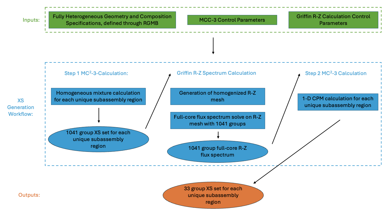
Figure 1: Diagram of workflow outlining the different steps that are taken as part of the cross section generation workflow using Griffin and MC-3.
Figure 1 shows a schematic of the inputs and outputs related to the cross section generation workflow, as well as a blueprint for all of the steps taken as part of the cross section generation procedure. For the purposes of this tutorial, it is assumed that fast reactor cross sections are generated using a 2-step method in MC-3 with an intermediate R-Z flux calculation, as this method has been shown to generate the most accurate cross section datasets for use with downstream full-core eigenvalue calculations (Stauff et al., 2022).
Griffin requires three pieces of information as inputs to the cross section generation workflow :
the input heterogeneous geometry, defined using the Reactor Geometry Mesh Builder (RGMB) mesh generators
all parameters related to the execution of 2-step MC-3 cross section generation
all parameters related to the intermediate Griffin R-Z flux calculation.
RGMB mesh generators provide a simplified pathway for defining pin, assembly, and core geometries that follow structured lattice patterns. Moreover, these mesh generators also define region ID mappings directly on the mesh. Through these specifications, Griffin is able to automatically determine unique subassembly regions based on geometrical and region ID based differences, and this information can then inform how to automatically generate downstream R-Z and assembly-homogenized meshes used as part of Griffin calculations, as well as provide information about how to setup the MCC-3 calculations that are needed. More information about how to perform mesh generation through RGMB will be provided in Heterogeneous input mesh generation through RGMB mesh generators. In addition to the input mesh, the rest of the input file describes the control parameters for the Griffin and MC-3 calculations that comprise the cross section generation workflow, where a special [MCC3CrossSection] block is used to define parameters specific to this workflow. As output to this cross section generation, a 33-group cross section library is generated for each unique subassembly region in ISOXML format, which can be directly read by Griffin to run subsequent full-core analysis.
As shown in Figure 1, the cross section generation workflow comprises of three steps. In the first step, pre-processed pointwise isotopic cross sections are condensed to a Ultra-Fine Group (UFG) structure for each subassembly type by solving the slowing down problem for a homogeneous mixture based on the composition of the subassembly under consideration. In this particular tutorial problem, the UFG structure follows the ANL1041 group structure. It should also be noted that a unique subassembly region is defined as a combination of assembly location and axial location that possesses a unique geometry and assignment of region IDs within the subassembly region. Going forward, this MCC-3 calculation will be referred to as the "Step 1 MC-3 Calculation".
From the UFG cross section set for each subassembly region, a whole-core transport calculation is performed in a cylindrical-Z (R-Z) geometry to calculate the full-core UFG flux distribution to account for spectral effects between subassembly regions. The R-Z geometry is automatically created by preserving the total volume of like hexagonal assemblies that are grouped together within the assembly lattice. This spectrum calculation is done in Griffin using the DFEM-SN solver, and is referred to as the "Griffin R-Z Spectrum Calculation". The flux spectrum is then passed back to MC-3 in the final step of the cross section generation workflow, where the UFG cross sections are condensed to a Broad Group (BG) cross section set for each unique subassembly region, referred here onwards as the "Step 2 MC-3 Calculation". In this example, the BG structure will follow the ANL33 group structure, and for each subassembly region that contains fuel or strong neutron absorbers, the cross section condensation step can optionally involve a 1-D collision probability method (CPM) calculation to account for local heterogeneity effects within the subassembly region. The 33-group BG cross section data library will be outputted as a single ISOXML file.
The cross section generation workflow has been implemented in such a way that many of the input file generation steps, data transfers, and generation of input meshes and problem boundaries related to how Griffin and MCC-3 operate have been automated. It should also be noted that all intermediate meshes and composition mappings are also automatically inferred from the input heterogeneous mesh, which directly contains all region ID and mesh specifications for each pin, assembly, and core region. Users who require more background on this cross section generation workflow are referred to (Lee et al., 2018) and (Lee et al., 2023). The following section details how to define the heterogeneous input mesh through the use of RGMB mesh generators, as well as how to set the control parameters within the Griffin input file to dictate how MCC-3 and Griffin are executed within the three steps that comprise the cross section generation workflow.
Input File Description for Cross Section Generation Workflow
This section focuses on the input files needed to run the cross section generation worfklow. For this tutorial, this step is comprised of three input files: abtr_het_mesh.i defines the heterogeneous mesh through RGMB mesh generators, xs_generation_mesh.i takes this heterogeneous mesh as input and generates the equivalent R-Z mesh that will be used as part of the Griffin R-Z spectrum calculation, while xs_generation.i defines all control parameters related to the cross section generation workflow. Using the !include <FILENAME>.i command in the input file, xs_generation.i directly imports the contents of xs_generation_mesh.i, which also uses this command to directly import the contents of abtr_het_mesh.i. This makes it so that only the file xs_generation.i needs to be called from the command line in order to expand the contents of all three input files and run the entire cross section generation workflow. The commands to run the cross section generation workflow from start to finish are shown below:
# Generate equivalent R-Z spectrum mesh and run XS generation workflow through Griffin
mpirun -np <N_PROC_TOTAL> /path/to/griffin/griffin-opt -i xs_generation.i
, where <N_PROC_TOTAL> refers to the total number of MPI processes available for the simulation. abtr_het_mesh.i and xs_generation_mesh.i generate an output 2-D R-Z mesh from an input mesh that represents the geometry and material ID assignment for the 3-D heterogeneous ABTR core. xs_generation.i contains all of the information related to the cross section generation worklow. Heterogeneous input mesh generation through RGMB mesh generators and Definition of equivalent R-Z core through EquivalentCoreMeshGenerator describe sections of abtr_het_mesh.i and xs_generation_mesh.i in more detail, respectively, while Input Parameters Specific to MC-3 Execution and Overall Cross Section Generation Workflow and Input Parameters Specific to Intermediate Griffin R-Z flux calculation describe the specifics of xs_generation.i.
Heterogeneous input mesh generation through RGMB mesh generators
The ReactorMeshParams, PinMeshGenerator, AssemblyMeshGenerator, and CoreMeshGenerator in abtr_het_mesh.i make use of the RGMB mesh generation system within the Reactor module to streamline the definition of latticed core geometries and the reporting IDs associated with such structures (Shemon et al., 2023). Mesh generation through RGMB is a requirement for taking advantage of Griffin's SFR cross section generation workflow, as it ensures that all reporting IDs related to region ID mappings as well as IDs corresponding to groupings of pin structures, assembly structures, and axial layers are defined in a consistent and predictable manner.
At the top of the abtr_het_mesh.i file, all global variables related to the mesh geometry as well as the region/material IDs are defined as global constants to be used within the [Mesh] block. For the purposes of this workflow, the region/material IDs defined in this section can be understood as unique material zones on the heterogeneous mesh that each have their own mappings of isotopic compositions. Thus, for this problem there are 12 unique material types within the heterogeneous core specifications.
fuel_pin_pitch = 0.908
fuel_clad_r_i = 0.348
fuel_clad_r_o = 0.40333 # Adjusts for wire wrap diameter
control_pin_pitch = 1.243
control_clad_r_i = 0.485
control_clad_r_o = 0.55904 # Adjusts for wire wrap diameter
control_duct_pitch_inner = 12.198
control_duct_pitch_outer = 12.798
duct_pitch_inner = 13.598
duct_pitch_outer = 14.198
assembly_pitch = 14.598

z_active_core_lower = 60
z_active_core_upper = 140
z_sodium_gp_upper = 160
z_gp_upper = 260

dz_active_core_lower = '${fparse z_active_core_lower - 0}'
dz_active_core_upper = '${fparse z_active_core_upper - z_active_core_lower}'
dz_sodium_gp_upper = '${fparse z_sodium_gp_upper - z_active_core_upper}'
dz_gp_upper = '${fparse z_gp_upper - z_sodium_gp_upper}'

max_axial_mesh_size = 8
naxial_active_core_lower = '${fparse ceil(dz_active_core_lower / max_axial_mesh_size)}'
naxial_active_core_upper = '${fparse ceil(dz_active_core_upper / max_axial_mesh_size)}'
naxial_sodium_gp_upper = '${fparse ceil(dz_sodium_gp_upper / max_axial_mesh_size)}'
naxial_gp_upper = '${fparse ceil(dz_gp_upper / max_axial_mesh_size)}'

# ==============================================================================
# Material IDs
# ==============================================================================
mid_fuel_1 = 1
mid_fuel_2 = 2
mid_fuel_3 = 3
mid_b4c = 4
mid_ht9 = 5
mid_sodium = 6
mid_rad_refl = 7
mid_rad_shld = 8
mid_lower_refl = 9
mid_upper_na_plen = 10
mid_upper_gas_plen = 11
mid_control_empty = 12Within the [Mesh] block, the ReactorMeshParams object defines the global parameters related to the heterogeneous mesh. This includes:
Number of dimensions of the output mesh, controlled by
ReactorMeshParams/dimGeometry type of the output mesh (Hexagonal or Cartesian), controlled by
ReactorMeshParams/geomAssembly pitch, controlled by
ReactorMeshParams/assembly_pitchAssembly layer thicknesses and number of subintervals per axial layer, controlled by
ReactorMeshParams/axial_regionsandReactorMeshParams/axial_mesh_intervals, respectivelyBoundary IDs assigned to the top, bottom, and radial sidesets of the outer boundary of the reactor core, controlled by
ReactorMeshParams/top_boundary_id,ReactorMeshParams/bottom_boundary_idandReactorMeshParams/radial_boundary_id, respectively.
The axial discretization used by the heterogeneous mesh, controlled by ReactorMeshParams/axial_regions and ReactorMeshParams/axial_mesh_intervals, will also be used as is to define the axial discretization of the equivalent homogenized, partially homogenized, or 2-D R-Z that is outputted by the [Mesh] block.
  # Define global reactor mesh parameters
  [rmp]
    type = ReactorMeshParams
    dim = 3
    geom = "Hex"
    assembly_pitch = ${assembly_pitch}
    axial_regions = '${dz_active_core_lower} ${dz_active_core_upper} ${dz_sodium_gp_upper} ${dz_gp_upper}'
    axial_mesh_intervals = '${naxial_active_core_lower} ${naxial_active_core_upper}
                            ${naxial_sodium_gp_upper} ${naxial_gp_upper}'
    top_boundary_id = 201
    bottom_boundary_id = 202
    radial_boundary_id = 203
    flexible_assembly_stitching = true
[]Pin structures are defined by calling PinMeshGenerator, and four different pin types are created, three of them used to create three fuel assembly types of varying fuel compositions, and one to define the control rod assembly. Each of these pin definitions have a unique values for PinMeshGenerator/pin_type to indicate uniqueness of pin types to the RGMB workflow.
  # Define constituent pins of fuel assemblies
  [fuel_pin_1]
    type = PinMeshGenerator
    reactor_params = rmp
    pin_type = 1
    pitch = ${fuel_pin_pitch}
    num_sectors = 2
    ring_radii = '${fuel_clad_r_i} ${fuel_clad_r_o}'
    mesh_intervals = '1 1 1' # Fuel, cladding, background
    region_ids = '${mid_lower_refl}     ${mid_lower_refl}     ${mid_lower_refl};
                  ${mid_fuel_1}         ${mid_ht9}            ${mid_sodium};
                  ${mid_upper_na_plen}  ${mid_upper_na_plen}  ${mid_upper_na_plen};
                  ${mid_upper_gas_plen} ${mid_upper_gas_plen} ${mid_upper_gas_plen}' # Fuel, cladding, background
    quad_center_elements = false
  []
  [fuel_pin_2]
    type = PinMeshGenerator
    reactor_params = rmp
    pin_type = 2
    pitch = ${fuel_pin_pitch}
    num_sectors = 2
    ring_radii = '${fuel_clad_r_i} ${fuel_clad_r_o}'
    mesh_intervals = '1 1 1' # Fuel, cladding, background
    region_ids = '${mid_lower_refl}     ${mid_lower_refl}     ${mid_lower_refl};
                  ${mid_fuel_2}         ${mid_ht9}            ${mid_sodium};
                  ${mid_upper_na_plen}  ${mid_upper_na_plen}  ${mid_upper_na_plen};
                  ${mid_upper_gas_plen} ${mid_upper_gas_plen} ${mid_upper_gas_plen}' # Fuel, cladding, background
    quad_center_elements = false
  []
  [fuel_pin_3]
    type = PinMeshGenerator
    reactor_params = rmp
    pin_type = 3
    pitch = ${fuel_pin_pitch}
    num_sectors = 2
    ring_radii = '${fuel_clad_r_i} ${fuel_clad_r_o}'
    mesh_intervals = '1 1 1' # Fuel, cladding, background
    region_ids = '${mid_lower_refl}     ${mid_lower_refl}     ${mid_lower_refl};
                  ${mid_fuel_3}         ${mid_ht9}            ${mid_sodium};
                  ${mid_upper_na_plen}  ${mid_upper_na_plen}  ${mid_upper_na_plen};
                  ${mid_upper_gas_plen} ${mid_upper_gas_plen} ${mid_upper_gas_plen}' # Fuel, cladding, background
    quad_center_elements = false
  []
  # Define constituent pin of control assembly
  [control_pin]
    type = PinMeshGenerator
    reactor_params = rmp
    pin_type = 4
    pitch = ${control_pin_pitch}
    num_sectors = 2
    ring_radii = '${control_clad_r_i} ${control_clad_r_o}'
    mesh_intervals = '1 1 1' # Fuel, cladding, background
    region_ids = '${mid_control_empty} ${mid_control_empty} ${mid_control_empty};
                  ${mid_control_empty} ${mid_control_empty} ${mid_control_empty};
                  ${mid_b4c}            ${mid_ht9}            ${mid_sodium};
                  ${mid_b4c}            ${mid_ht9}            ${mid_sodium}' # Fuel, cladding, background
    quad_center_elements = false
[]Pins are defined as a collection of ring radii surrounded by a background region and an optional duct region. The following parameters control the geometrical aspects of the pin structure:
pitch: pitch of pin structurenum_sectors: number of azimuthal sectors for each side of the hexagonal pinring_radii: location of radii used to define circular pin section of meshmesh_intervals: Number of subintervals to discretize the pin structure, where the values correspond to the innermost to outermost ring regions, the background region, and finally the innermost to outermost duct regions.
The region_ids parameter is used to set the region ID reporting IDs for the pin structure, where the horizontal axis from left to right represents the region IDs of the innermost to outermost radial ring regions, followed by the background region, and the vertical axis from top to bottom represents the region IDs of the four axial layers in the problem, from bottom to top. These region ID mappings are iterated on for each combination of axial and radial assembly location to determine which subassembly regions have unique material zone mappings on the heterogeneous mesh.
These four pin types are then stitched into assembly structures by calling AssemblyMeshGenerator. Here, three different fuel assembly types and one control assembly type are created, each of which has a different value for AssemblyMeshGenerator/assembly_type to indicate uniqueness of assembly types to the RGMB workflow. AssemblyMeshGenerator/background_intervals and AssemblyMeshGenerator/duct_intervals control how many subdiscretizations should be applied for each background and duct region, respectively, and AssemblyMeshGenerator/duct_halfpitch defines the halfpitch of each duct region.
  # Define fuel assemblies
  [fuel_assembly_1]
    type = AssemblyMeshGenerator
    assembly_type = 1
    background_intervals = 1
    background_region_id = '${mid_lower_refl} ${mid_sodium} ${mid_upper_na_plen} ${mid_upper_gas_plen}'
    duct_halfpitch = '${fparse duct_pitch_inner / 2} ${fparse duct_pitch_outer / 2}'
    duct_intervals = '1 1'
    duct_region_ids = ' ${mid_lower_refl}     ${mid_lower_refl};
                        ${mid_ht9}            ${mid_sodium};
                        ${mid_upper_na_plen}  ${mid_upper_na_plen};
                        ${mid_upper_gas_plen} ${mid_upper_gas_plen}'
    inputs = 'fuel_pin_1'
    pattern = '0 0 0 0 0 0 0 0 0;
              0 0 0 0 0 0 0 0 0 0;
             0 0 0 0 0 0 0 0 0 0 0;
            0 0 0 0 0 0 0 0 0 0 0 0;
           0 0 0 0 0 0 0 0 0 0 0 0 0;
          0 0 0 0 0 0 0 0 0 0 0 0 0 0;
         0 0 0 0 0 0 0 0 0 0 0 0 0 0 0;
        0 0 0 0 0 0 0 0 0 0 0 0 0 0 0 0;
       0 0 0 0 0 0 0 0 0 0 0 0 0 0 0 0 0;
        0 0 0 0 0 0 0 0 0 0 0 0 0 0 0 0;
         0 0 0 0 0 0 0 0 0 0 0 0 0 0 0;
          0 0 0 0 0 0 0 0 0 0 0 0 0 0;
           0 0 0 0 0 0 0 0 0 0 0 0 0;
            0 0 0 0 0 0 0 0 0 0 0 0;
             0 0 0 0 0 0 0 0 0 0 0;
              0 0 0 0 0 0 0 0 0 0;
               0 0 0 0 0 0 0 0 0'
  []
  [fuel_assembly_2]
    type = AssemblyMeshGenerator
    assembly_type = 2
    background_intervals = 1
    background_region_id = '${mid_lower_refl} ${mid_sodium} ${mid_upper_na_plen} ${mid_upper_gas_plen}'
    duct_halfpitch = '${fparse duct_pitch_inner / 2} ${fparse duct_pitch_outer / 2}'
    duct_intervals = '1 1'
    duct_region_ids = ' ${mid_lower_refl}     ${mid_lower_refl};
                        ${mid_ht9}            ${mid_sodium};
                        ${mid_upper_na_plen}  ${mid_upper_na_plen};
                        ${mid_upper_gas_plen} ${mid_upper_gas_plen}'
    inputs = 'fuel_pin_2'
    pattern = '0 0 0 0 0 0 0 0 0;
              0 0 0 0 0 0 0 0 0 0;
             0 0 0 0 0 0 0 0 0 0 0;
            0 0 0 0 0 0 0 0 0 0 0 0;
           0 0 0 0 0 0 0 0 0 0 0 0 0;
          0 0 0 0 0 0 0 0 0 0 0 0 0 0;
         0 0 0 0 0 0 0 0 0 0 0 0 0 0 0;
        0 0 0 0 0 0 0 0 0 0 0 0 0 0 0 0;
       0 0 0 0 0 0 0 0 0 0 0 0 0 0 0 0 0;
        0 0 0 0 0 0 0 0 0 0 0 0 0 0 0 0;
         0 0 0 0 0 0 0 0 0 0 0 0 0 0 0;
          0 0 0 0 0 0 0 0 0 0 0 0 0 0;
           0 0 0 0 0 0 0 0 0 0 0 0 0;
            0 0 0 0 0 0 0 0 0 0 0 0;
             0 0 0 0 0 0 0 0 0 0 0;
              0 0 0 0 0 0 0 0 0 0;
               0 0 0 0 0 0 0 0 0'
  []
  [fuel_assembly_3]
    type = AssemblyMeshGenerator
    assembly_type = 3
    background_intervals = 1
    background_region_id = '${mid_lower_refl} ${mid_sodium} ${mid_upper_na_plen} ${mid_upper_gas_plen}'
    duct_halfpitch = '${fparse duct_pitch_inner / 2} ${fparse duct_pitch_outer / 2}'
    duct_intervals = '1 1'
    duct_region_ids = ' ${mid_lower_refl}     ${mid_lower_refl};
                        ${mid_ht9}            ${mid_sodium};
                        ${mid_upper_na_plen}  ${mid_upper_na_plen};
                        ${mid_upper_gas_plen} ${mid_upper_gas_plen}'
    inputs = 'fuel_pin_3'
    pattern = '0 0 0 0 0 0 0 0 0;
              0 0 0 0 0 0 0 0 0 0;
             0 0 0 0 0 0 0 0 0 0 0;
            0 0 0 0 0 0 0 0 0 0 0 0;
           0 0 0 0 0 0 0 0 0 0 0 0 0;
          0 0 0 0 0 0 0 0 0 0 0 0 0 0;
         0 0 0 0 0 0 0 0 0 0 0 0 0 0 0;
        0 0 0 0 0 0 0 0 0 0 0 0 0 0 0 0;
       0 0 0 0 0 0 0 0 0 0 0 0 0 0 0 0 0;
        0 0 0 0 0 0 0 0 0 0 0 0 0 0 0 0;
         0 0 0 0 0 0 0 0 0 0 0 0 0 0 0;
          0 0 0 0 0 0 0 0 0 0 0 0 0 0;
           0 0 0 0 0 0 0 0 0 0 0 0 0;
            0 0 0 0 0 0 0 0 0 0 0 0;
             0 0 0 0 0 0 0 0 0 0 0;
              0 0 0 0 0 0 0 0 0 0;
               0 0 0 0 0 0 0 0 0'
  []
  # Define control assembly
  [control_assembly]
    type = AssemblyMeshGenerator
    assembly_type = 4
    background_intervals = 1
    background_region_id = '${mid_control_empty} ${mid_control_empty} ${mid_sodium} ${mid_sodium}'
    duct_halfpitch = '${fparse control_duct_pitch_inner / 2} ${fparse control_duct_pitch_outer / 2}
                      ${fparse duct_pitch_inner / 2}         ${fparse duct_pitch_outer / 2}'
    duct_intervals = '1 1 1 1'
    duct_region_ids = '${mid_control_empty} ${mid_control_empty} ${mid_control_empty} ${mid_control_empty};
                       ${mid_control_empty} ${mid_control_empty} ${mid_control_empty} ${mid_control_empty};
                       ${mid_ht9}           ${mid_sodium}        ${mid_ht9}           ${mid_sodium};
                       ${mid_ht9}           ${mid_sodium}        ${mid_ht9}           ${mid_sodium}'
    inputs = 'control_pin'
    pattern = '0 0 0 0 0 0;
              0 0 0 0 0 0 0;
             0 0 0 0 0 0 0 0;
            0 0 0 0 0 0 0 0 0;
           0 0 0 0 0 0 0 0 0 0;
          0 0 0 0 0 0 0 0 0 0 0;
           0 0 0 0 0 0 0 0 0 0;
            0 0 0 0 0 0 0 0 0;
             0 0 0 0 0 0 0 0;
              0 0 0 0 0 0 0;
               0 0 0 0 0 0'
[]Similar to PinMeshGenerator/region_ids, AssemblyMeshGenerator/background_region_id and AssemblyMeshGenerator/duct_region_ids set the region IDs of the background and duct regions, respectively, where the horizontal axis represents the radial region IDs (from innermost to outermost), and the vertical axis represents the axial region IDs (from bottom to top). Figure 2 shows how the 3-D region IDs are represented for Mesh/fuel_assembly_1 and Mesh/control_assembly.
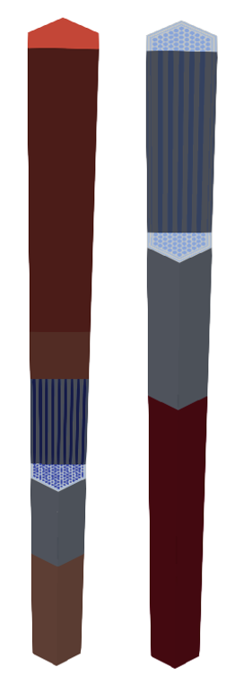
Figure 2: 3D region ID distribution of Mesh/fuel_assembly_1 (left) and Mesh/control_assembly (right)
In order to define homogenized assembly regions, PinMeshGenerator is called with PinMeshGenerator/use_as_assembly set to true. This is done so that the resulting mesh, which acts as an assembly mesh but does not have any constituent pin structures, can be stitched into CoreMeshGenerator in the next step. In this problem, this is done for the reflector and shielding regions, which are represented using a single region ID throughout the entire axial and radial extent.
# ==============================================================================
# ABTR Equivalent-full core cross section generation mesh
# Application: Griffin
# POC: Shikhar Kumar (kumars at anl.gov)
# If using or referring to this model, please cite as explained in
# https://mooseframework.inl.gov/virtual_test_bed/citing.html
# ==============================================================================

!include abtr_het_mesh.i
[Mesh]
  # Define equivalent RZ core from input heterogeneous RGMB core
  [rz_core]
    type = EquivalentCoreMeshGenerator
    input = het_core
    target_geometry = rz
    max_radial_mesh_size = 5
    radial_boundaries = '7.66 20.28 27.63 35.95 48.47 64.13 94.18 108.12'
    radial_assembly_names = 'control_assembly fuel_assembly_1 fuel_assembly_3
                             control_assembly fuel_assembly_1 fuel_assembly_2
                             reflector_assembly shielding_assembly'
    debug_equivalent_core = true
  []
  # Define and apply a coarse RZ mesh
  [rz_coarse_mesh]
    type = CartesianMeshGenerator
    dim = 2
    dx = '7.66 12.61 7.36 8.31 12.52 15.65 30.06 13.94'
    dy = '60 80 20 100'
  []
  [rz_coarse_id]
    type = CoarseMeshExtraElementIDGenerator
    input = rz_core
    coarse_mesh = rz_coarse_mesh
    extra_element_id_name = coarse_elem_id
  []
  coord_type = RZ
  data_driven_generator = rz_core
[]
The resulting assembly structure definitions can then be stitched together to define the heterogeneous core mesh. Here, a dummy assembly mesh does not have to be explicitly defined, and can be specified in CoreMeshGenerator/inputs by providing a dummy assembly name in CoreMeshGenerator/dummy_assembly_name. Figure 3 shows the resulting region ID distribution for the 3-D heterogeneous reactor core mesh.
  # Define heterogeneous core
  [het_core]
    type = CoreMeshGenerator
    inputs = 'fuel_assembly_1 fuel_assembly_2 fuel_assembly_3
              control_assembly reflector_assembly shielding_assembly
              dummy'
    dummy_assembly_name = 'dummy'
    pattern = '6 6 5 5 5 5 5 6 6;
              6 5 5 4 4 4 4 5 5 6;
             5 5 4 4 4 4 4 4 4 5 5;
            5 4 4 4 4 1 1 4 4 4 4 5;
           5 4 4 4 1 1 3 1 1 4 4 4 5;
          5 4 4 1 1 2 0 0 4 1 1 4 4 5;
         5 4 4 1 3 0 0 2 0 0 3 1 4 4 5;
        6 5 4 4 1 0 3 0 0 3 0 1 4 4 5 6;
       6 5 4 4 1 4 0 0 3 0 0 2 1 4 4 5 6;
        6 5 4 4 1 0 2 0 0 2 0 1 4 4 5 6;
         5 4 4 1 3 0 0 3 0 0 3 1 4 4 5;
          5 4 4 1 1 2 0 0 4 1 1 4 4 5;
           5 4 4 4 1 1 3 1 1 4 4 4 5;
            5 4 4 4 4 1 1 4 4 4 4 5;
             5 5 4 4 4 4 4 4 4 5 5;
              6 5 5 4 4 4 4 5 5 6;
               6 6 5 5 5 5 5 6 6'
    extrude = true
  []
[]
 mesh generators.](plots/hetcore_region_ids.png)
Figure 3: 3D region ID distribution of heterogeneous core created through RGMB mesh generators.
Definition of equivalent R-Z core through EquivalentCoreMeshGenerator
Through the definition of the heterogeneous core input mesh using RGMB mesh generators, a Griffin-specific mesh generator called EquivalentCoreMeshGenerator is called to enable all downstream calculations used as part of the cross section generation workflow.
  # Define equivalent RZ core from input heterogeneous RGMB core
  [rz_core]
    type = EquivalentCoreMeshGenerator
    input = het_core
    target_geometry = rz
    max_radial_mesh_size = 5
    radial_boundaries = '7.66 20.28 27.63 35.95 48.47 64.13 94.18 108.12'
    radial_assembly_names = 'control_assembly fuel_assembly_1 fuel_assembly_3
                             control_assembly fuel_assembly_1 fuel_assembly_2
                             reflector_assembly shielding_assembly'
    debug_equivalent_core = true
[]In this step, EquivalentCoreMeshGenerator accomplishes two tasks:
Generation of equivalent R-Z mesh for use with downstream Griffin R-Z spectrum calculation
Definition of all metadata related to setting up downstream MC-3 calculations.
Related to the first point, EquivalentCoreMeshGenerator/input takes a heterogeneous input core mesh defined through the use of CoreMeshGenerator, and creates an equivalent homogenized, partially homogenized, or 2-D R-Z mesh without the need for a user to generate this intermediate mesh from scratch. Since the downstream Griffin calculation in the cross section generation workflow requires a 2-D R-Z mesh, EquivalentCoreMeshGenerator/target_geometry is set to rz. However, at the full-core analysis step described in Input File Description for Full-Core Eigenvalue Calculation, a fully homogeneous input mesh needs to be generated from the input heterogeneous mesh instead, so this is done by following the same mesh generation workflow and setting EquivalentCoreMeshGenerator/target_geometry to full_hom. Other options for this parameter include ring_het and duct_het for ring-heterogeneous and duct heterogeneous intermediate output meshes, respectively.
Most of the remaining parameters in the [rz_core] control how the 2-D R-Z mesh should be discretized, where max_radial_mesh_size controls the maximum radial mesh size to subdivide the radial boundaries of the 2-D R-Z mesh. By default, EquivalentCoreMeshGenerator automatically infers the R-Z mesh boundaries by collapsing the input core lattice pattern by each hexagonal ring and grouping like assembly types. However, the R-Z mesh radial boundary and region assignments can also be specified manually by setting EquivalentCoreMeshGenerator/radial_boundaries and EquivalentCoreMeshGenerator/radial_assembly_names, respectively, where the names in EquivalentCoreMeshGenerator/radial_assembly_names correspond to the assembly names defined in CoreMeshGenerator/inputs to place the homogenized region IDs in each radial and axial region of the 2-D R-Z mesh. The manual approach is taken in this example, where the radial boundary and region assignments are based on prior studies done for the ABTR core (Stauff et al., 2022). The axial discretization used in the 2-D R-Z mesh uses the same discretization as the input heterogeneous mesh, which is controlled by the parameters ReactorMeshParams/axial_regions and ReactorMeshParams/axial_mesh_intervals.
 mesh generators (left).](plots/eqv_rzcore.png)
Figure 4: Generation of 2-D R-Z core mesh (right) from heterogeneous core created through RGMB mesh generators (left).
Figure 4 shows how the input heterogeneous mesh is converted to an equivalent 2-D R-Z mesh. This is done by iterating through each assembly type defined within the core, and determining which combinations of (assembly type, axial layer) are unique, where uniqueness is based on the heterogeneous mesh geometry of subassembly region AND the distribution of heterogeneous region IDs within the subassembly region. In order to illustrate this point, notice how the homogenized fuel subassemblies corresponding to [fuel_assembly_1], [fuel_assembly_2], [fuel_assembly_3] in the 2-D R-Z mesh have different IDs associated with the second axial layer from the bottom. Despite the heterogeneous geometry of these three subassembly regions being identical from a mesh discretization standpoint, EquivalentCoreMeshGenerator designates these homogenized regions as being unique due to the fact that the region IDs in the heterogeneous fuel pin regions of these subassemblies are not identical. Table 1 describes the mapping of each combination of assembly name and axial layer to the homogenized subassembly ID (defined in increments of 100).
Table 1: Mapping of assembly name and axial ID to subassembly ID
| Heterogeneous assembly name | Axial ID (1 = bottommost layer, 4 = topmost layer) | Subassembly region ID |
|---|---|---|
| fuel_assembly_1 | 1 | 100 |
| 2 | 200 | |
| 3 | 300 | |
| 4 | 400 | |
| fuel_assembly_2 | 1 | 100 |
| 2 | 500 | |
| 3 | 300 | |
| 4 | 400 | |
| fuel_assembly_3 | 1 | 100 |
| 2 | 600 | |
| 3 | 300 | |
| 4 | 400 | |
| control_assembly | 1 | 700 |
| 2 | 700 | |
| 3 | 800 | |
| 4 | 800 | |
| reflector_assembly | 1 | 900 |
| 2 | 900 | |
| 3 | 900 | |
| 4 | 900 | |
| shielding_assembly | 1 | 1000 |
| 2 | 1000 | |
| 3 | 1000 | |
| 4 | 1000 |
The mapping shown in Table 1 is computed by EquivalentCoreMeshGenerator and stored as metadata on the mesh. This metadata is what is primarily used to set up the MCC-3 execution and MCC-3 input file generation, which all happens under the hood. For example, each subassembly region ID shown in the third column of Table 1 represents a separate subassembly region for which MC-3 needs to be executed. The following metadata is also defined by EquivalentCoreMeshGenerator, which is used by downstream MC-3 calculations:
Homogenized volume fractions: For each subassembly ID shown in Table 1, a list of volume fractions for each heterogeneous region ID found within the subassembly is stored. This is used in the Step 1 MC-3 calculation step to set the compositions of the homogenized mixture calculation for each subassembly region.
1-D radial boundaries: For each subassembly ID shown in Table 1, the heterogeneous subassembly geometry and region ID layout is represented as a series of volume-preserved concentric rings, and this 1-D ring representation is used by the Step 2 MC-3 calculation to setup the 1-D CPM calculations wherever needed.
For a more comprehensive list of metadata stored by EquivalentCoreMeshGenerator, the console output from setting EquivalentCoreMeshGenerator/debug_equivalent_core = true can be inspected. As a final step for mesh generation, an explicity defined coarse mesh is defined for the output R-Z mesh in order to use with Coarse Mesh Finite Differences (CMFD) acceleration as part of the downstream Griffin R-Z spectrum calculation step, and setting Mesh/coord_type = RZ specifies that an RZ coordinate system should be used with the 2D mesh.
  # Define and apply a coarse RZ mesh
  [rz_coarse_mesh]
    type = CartesianMeshGenerator
    dim = 2
    dx = '7.66 12.61 7.36 8.31 12.52 15.65 30.06 13.94'
    dy = '60 80 20 100'
  []
  [rz_coarse_id]
    type = CoarseMeshExtraElementIDGenerator
    input = rz_core
    coarse_mesh = rz_coarse_mesh
    extra_element_id_name = coarse_elem_id
  []
  coord_type = RZ
data_driven_generator = rz_coreFinally, Mesh/data_driven_generator indicates to the mesh generator system that it should define the input heterogeneous mesh specifications through metadata defined by RGMB, instead of building a physical heterogeneous input mesh. The value of this parameter should point to the name of the EquivalentCoreMeshGenerator instance. The data-driven model is an optimization that Griffin requires to speed up mesh generation workflows that invoke EquivalentCoreMeshGenerator.
Input Parameters Specific to MC-3 Execution and Overall Cross Section Generation Workflow
As explained in Heterogeneous input mesh generation through RGMB mesh generators and Definition of equivalent R-Z core through EquivalentCoreMeshGenerator, the combination of abtr_het_mesh.i and xs_generation_mesh.i defines the [Mesh] block that generates a 2-D R-Z mesh from a fully-heterogeneous core geometry definition. However, since the output mesh does not contain any information about the isotopic compositions related to each region ID defined on the input mesh, the [Compositions] block in xs_generation.i is used to map the region IDs defined in xs_generation_mesh.i to physical isotopic compositions within each heterogeneous region:
[Compositions]
  [fuel1]
    type = IsotopeComposition
    isotope_densities = 'ZR90 3.91909E-03
                         ZR91 8.45242E-04
                         ZR92 1.27794E-03
                         ZR94 1.26746E-03
                         ZR96 1.99934E-04
                         U235 3.33146E-05
                         U236 2.65386E-06
                         U238 2.15143E-02
                         NP237 2.37839E-05
                         PU238 1.01970E-05
                         PU239 3.68541E-03
                         PU240 4.94293E-04
                         PU241 5.33116E-05
                         PU242 2.35963E-05
                         AM241 2.46886E-05
                         AM242M 6.47017E-07
                         AM243 5.15491E-06
                         CM244 1.28342E-06'
    density_type = atomic
    composition_ids = 1
  []
  [fuel2]
    type = IsotopeComposition
    isotope_densities = 'ZR90 3.91839E-03
                         ZR91 8.45090E-04
                         ZR92 1.27771E-03
                         ZR94 1.26723E-03
                         ZR96 1.99898E-04
                         U235 3.16338E-05
                         U236 2.51998E-06
                         U238 2.04290E-02
                         NP237 2.25841E-05
                         PU238 1.27905E-05
                         PU239 4.62263E-03
                         PU240 6.20033E-04
                         PU241 6.68729E-05
                         PU242 2.95978E-05
                         AM241 2.34432E-05
                         AM242M 6.14392E-07
                         AM243 4.89465E-06
                         CM244 1.21867E-06'
    density_type = atomic
    composition_ids = 2
  []
  [fuel3]
    type = IsotopeComposition
    isotope_densities = 'ZR90 3.91871E-03
                         ZR91 8.45159E-04
                         ZR92 1.27782E-03
                         ZR94 1.26734E-03
                         ZR96 1.99914E-04
                         U235 3.24342E-05
                         U236 2.58374E-06
                         U238 2.09457E-02
                         NP237 2.31554E-05
                         PU238 1.15555E-05
                         PU239 4.17640E-03
                         PU240 5.60169E-04
                         PU241 6.04162E-05
                         PU242 2.67400E-05
                         AM241 2.40363E-05
                         AM242M 6.29931E-07
                         AM243 5.01855E-06
                         CM244 1.24951E-06'
    density_type = atomic
    composition_ids = 3
  []
  [control_b4c]
    type = IsotopeComposition
    isotope_densities = 'B10 1.86773e-02
                         B11 7.47092e-02
                         C0 2.33466e-02'
    density_type = atomic
    composition_ids = 4
  []
  [shield_b4c]
    type = IsotopeComposition
    isotope_densities = 'B10 1.77984e-02
                         B11 7.11935e-02
                          C0 2.22479e-02'
    density_type = atomic
  []
  [ht9]
    type = IsotopeComposition
    isotope_densities = 'CR50 4.57952E-04
                         CR52 8.83105E-03
                         CR53 1.00138E-03
                         CR54 2.49227E-04
                         MN55 4.66898E-04
                         FE54 4.14335E-03
                         FE56 6.50402E-02
                         FE57 1.50207E-03
                         FE58 1.99862E-04
                         NI58 2.97516E-04
                         NI60 1.14633E-04
                         NI61 4.96964E-06
                         NI62 1.59028E-05
                         NI64 4.05854E-06
                         MO92 7.39648E-05
                         MO94 4.60520E-05
                         MO95 7.93486E-05
                         MO96 8.30758E-05
                         MO97 4.76257E-05
                         MO98 1.20265E-04
                         MO100 4.79570E-05'
    density_type = atomic
    composition_ids = 5
  []
  [sodium]
    type = IsotopeComposition
    isotope_densities = 'NA23 2.22656e-02'
    density_type = atomic
    composition_ids = 6
  []
  [void]
    type = IsotopeComposition
    isotope_densities = 'HE4 1.0e-10'
    density_type = atomic
  []
  [radial_reflector]
    type = MixedComposition
    volume_fraction = 'sodium 0.1573 ht9 0.8427'
    composition_ids = 7
  []
  [radial_shielding]
    type = MixedComposition
    volume_fraction = 'sodium 0.1730 ht9 0.3041 shield_b4c 0.5229'
    composition_ids = 8
  []
  [lower_reflector]
    type = MixedComposition
    volume_fraction = 'sodium 0.3208 ht9 0.6792'
    composition_ids = 9
  []
  [upper_na_plenum]
    type = MixedComposition
    volume_fraction = 'sodium 0.7682 ht9 0.2318'
    composition_ids = 10
  []
  [upper_gas_plenum]
    type = MixedComposition
    volume_fraction = 'sodium 0.3208 ht9 0.2318 void 0.4474'
    composition_ids = 11
  []
  [control_empty]
    type = MixedComposition
    volume_fraction = 'sodium 0.9217 ht9 0.0783'
    composition_ids = 12
  []
[]IsotopeComposition is used to map compositions of individual isotopes and their atomic densities to a specific region, while MixedComposition is used to define compositions as volume fractions of existing IsotopeComposition instances. Compositions listed in the [Compositions] block are mapped to a region ID defined on the heterogeneous mesh through the parameter IsotopeComposition/composition_ids or MixedComposition/composition_ids.
xs_generation.i also defines the control logic related to the cross section generation workflow calculations in Griffin and MC-3 that are set by the user. This file resembles a typical Griffin input file except for a key difference, which is the [MCC3CrossSection] block. This input block controls aspects specific to the cross section generation workflow, and will be explained in more detail in this section.
[MCC3CrossSection]
  remove_pwfiles = false
  remove_inputs = true
  remove_outputs = true
  remove_xmlfiles = true
  endfb_version = 'ENDF/B-VII.0'
  library_pointwise = './'

  xml_macro_cross_section = true
  xml_filename = 'mcc3xs.xml'
  generate_core_input = true

  rz_calculation = true
  rz_spectrum_pn_order = 3
  group_structure = 'ANL33'
  rz_group_structure = 'ANL1041'

  map_het_grid_name = 'fuel1 Tfuel
                       fuel2 Tfuel
                       fuel3 Tfuel
                 control_b4c Tcool
                         ht9 Tcool
                      sodium Tcool
            radial_reflector Tcool
            radial_shielding Tcool
             lower_reflector Tcool
             upper_na_plenum Tcool
            upper_gas_plenum Tcool
               control_empty Tcool'
  map_het_grid_ref_value = 'Tfuel 900
                            Tcool 700'
  map_het_grid_values = 'Tfuel 900
                         Tcool 700'

  het_cross_sections = 'fuel1 fuel2 fuel3 control_b4c'
  max_het_mesh_size = 0.5
  target_core = full_hom
[]MCC3CrossSection/remove_pwfiles, MCC3CrossSection/remove_inputs, MCC3CrossSection/remove_outputs, and MCC3CrossSection/remove_xmlfiles control whether intermediate files generated by MCC-3 execution are removed after the simulation. MCC3CrossSection/griffin_data points to the location of where the griffin_data repository (a submodule of the Griffin repository) can be found, while MCC3CrossSection/endfb_version points to the ENDF/B library version that should be used for input cross section data. MCC3CrossSection/library_pointwise refers to a directory that has pre-generated pointwise data for use with Step 1 MCC-3 calculations. If this directory does not exist, this data library will be automatically generated as part of the cross section generation workflow execution.
MCC3CrossSection/xml_macro_cross_section controls whether the output cross section library should generate macroscopic multigroup cross sections (true) or microscopic multigroup cross sections (false), MCC3CrossSection/xml_filename controls the filename of the output xml cross section data library, and MCC3CrossSection/generate_core_input controls whether a Griffin input file should be automatically generated for running a full-core eigenvalue calculation. By setting this value to true, the input file that will be run in Input File Description for Full-Core Eigenvalue Calculation will be generated during the execution of the cross section workflow.
Additionaly, setting MCC3CrossSection/rz_calculation to true indicates that an intermediate Griffin flux RZ calculation should be conducted as part of the cross section generation workflow. MCC3CrossSection/rz_spectrum_pn_order sets the maximum flux moment order of the RZ flux spectrum, MCC3CrossSection/rz_group_structure sets the group structure of the intermediate flux spectrum calculation, while MCC3CrossSection/group_structure sets the final group structure of the output cross section library after running the Step 2 MC-3 calculation.
MCC3CrossSection/map_het_grid_name, MCC3CrossSection/map_het_grid_ref_value, and MCC3CrossSection/map_het_grid_values control how cross sections are tabulated as a function of tabulation variables such as temperature. MCC3CrossSection/map_het_grid_name maps each composition defined in the [Compositions] block that has an associated region ID to an associated grid variable. For the purposes of this tutorial, each heterogeneous region has a single temperature variable it is tabulated against, where Tfuel represents the fuel temperature, and Tcool represents the coolant temperature. MCC3CrossSection/map_het_grid_ref_value sets the reference value for each grid variable of interest, while MCC3CrossSection/map_het_grid_values defines all tabulated values that are assocaited with each grid variable.
Finally, MCC3CrossSection/target_core sets what type of core mesh will be generated for the full-core analysis step (fully homogeneous, duct heterogeneous, or ring heterogeneous), and this informs how many cross section regions should be computed for the output cross section dataset for each subassembly region. In this case, the full-core analysis step will be conducted on a fully homogeneous target core, so a single cross section material zone will be defined for each subassembly region, as opposed to multiple material zones per subassembly region for duct heterogeneous and ring heterogeneous target cores. MCC3CrossSection/het_cross_sections defines heterogeneous compositions that should be solved in the Step 2 MC-3 calculation step using the 1D CPM method to capture local spatial self-shielding effects, while MCC3CrossSection/max_het_mesh_size controls the maximum sub-discretization that should be used for each ring region within 1D CPM calculations.
In order to provide more detail about how Step 1 MC-3 input files are created, the metadata extracted from the mesh generator listed in MCC3CrossSection/rz_meshgenerator defines all unique subassembly regions within the reactor core. For each unique subassembly region, the homogenized mixture composition is then inferred using the volume fractions for each heterogeneous region IDs found in the subassembly (also computed as metadata), as well as the isotopic compositions for each of these region IDs. This mixture composition is written as part of the MC-3 input file before being executed by MC-3 and processed for use with the downstream Griffin R-Z flux spectrum calculation.
For Step 2 MC-3 input file generation, the same subassembly regions are considered as part of the BG cross section condensation step, with the primary difference being that some of these subassembly regions undergo a 1D CPM calculation step to incorporate local spatial self-shielding effects into the condensed cross sections. Only subassembly regions that contain region IDs associated with any of the compositions listed in MCCCrossSection/het_cross_sections will undergo this 1D CPM calculation step. Otherwise the condensation occurs assuming a homogenized mixture composition. Based on the data presented in Table 1, subassemblies with IDs 200, 500, 600, and 800 will undergo 1D CPM calculations, as these are the fuel and control subassemblies that contain the compositions specified by MCCCrossSection/het_cross_sections. The problem parameters for each of these 1D CPM calculations are based on the specifications of the ring boundaries and isotopic compositions for each ring region in the MC-3 input file. This is automatically inferred through the 1D ring model that is defined by EquivalentCoreMeshGenerator and stored as metadata. For example, for the fuel subassembly region with ID 200 (assembly named [fuel_assembly_1] in mesh input file at second-to-the-bottom axial layer) that undergoes the 1D CPM calculation step, Figure 5 shows the equivalent 1D ring geometry that MC-3 uses to run the 1D CPM calculation. Since 1D CPM calculations require a fission source to run, for heterogeneous regions such as control subassemblies that do not have any fuel material, the 1D CPM calculation will arbitrarily add a fuel region surrounding the 1D geometry, based on the homogenized composition of one of the fuel subassembly regions in the reactor core.
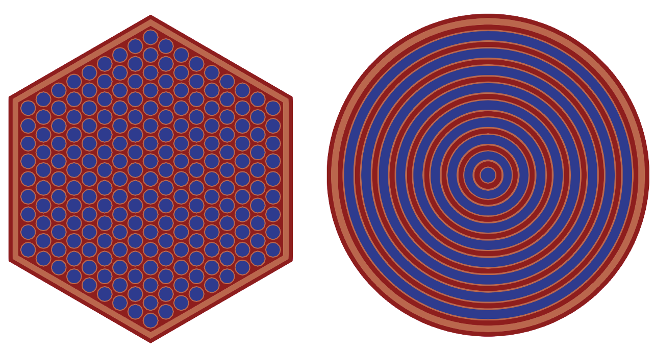
Figure 5: 2-D region ID layout of fuel subassembly region (left), and associated 1-D ring geometry that is solved in Step 2 MC-3 calculation step (right).
Input Parameters Specific to Intermediate Griffin R-Z flux calculation
Outside of the [Compositions] and [MCC3CrossSection] blocks, the rest of the xs_generation.i input file specifies control parameters for the intermediate R-Z flux spectrum calculation that is calculated in Griffin. The associated mesh that is defined in the [Mesh] block is the R-Z mesh that will be used to solve for the UFG flux spectrum, and the [TransportSystems] block sets up the eigenvalue transport problem that will be solved with the DFEM-SN solver, while the [Executioner] block defines the problem convergence tolerances and parameters specific to CMFD acceleration.
[TransportSystems]
  particle = neutron
  equation_type = eigenvalue
  G = 1041
  ReflectingBoundary = 'left'
  VacuumBoundary = 'right top bottom'
  [dfem_sn]
    scheme = DFEM-SN
    family = MONOMIAL
    order = FIRST
    AQtype = Gauss-Chebyshev
    NPolar = 3
    NAzmthl = 7
    NA = 3
    using_averaged_xs = true
    update_averaged_xs_on = INITIAL
  []
[]

[Executioner]
  type = SweepUpdate
  richardson_rel_tol = 1e-6
  richardson_abs_tol = 1e-6
  richardson_max_its = 1000
  richardson_value = eigenvalue
  inner_solve_type = GMRes
  max_inner_its = 2
  cmfd_acceleration = true
  truncate_scat_order = 0
  coarse_element_id = coarse_elem_id
  uniform_group_collapsing = 20
  prolongation_type = multiplicative
[]Here, TransportSystems/G must match the number of groups defined in MCC3CrossSection/rz_group_structure, and TransportSystems/VacuumBoundary and TransportSystems/ReflectingBoundary set the boundary conditions to be used in the 2-D R-Z problem. The resulting flux distribution that is solved for by Griffin is automatically passed to MC-3 to run the MC-3 step 2 calculations for each subassembly region.
Input File Description for Full-Core Eigenvalue Calculation
By running Griffin on the xs_generation.i file, two files are created that are used for the full-core eigenvalue calculation step that will be explained in this section. The first is the BG cross section library, named mcc3xs.xml (this name is controlled by MCCCrossSection/xml_filename), and the second is the Griffin input file that will be used for this section, named core_hom_macro.i (this is a fixed name, based on whether assembly homogenized cross sections are calculated, and whether microscopic or macroscopic cross sections are used in the output cross section library). The automatic generation of this input file streamlines the setup of the full-core analysis step, and the contents of this file are shown below:
# ==============================================================================
# ABTR Equivalent-full core calculation
# Application: Griffin
# POC: Shikhar Kumar (kumars at anl.gov)
# If using or referring to this model, please cite as explained in
# https://mooseframework.inl.gov/virtual_test_bed/citing.html
# ==============================================================================

# This input file is automatically generated by the Griffin [MCC3CrossSection] block when generating the 33 group SFR cross section library
# - User should define heterogeneous RGMB core mesh in [Mesh] block or as separate input file
# - User should set Mesh/eqv_core/input to name of heterogeneous RGMB CoreMeshGenerator mesh
# - User should make sure boundary sidesets (outer_core, top, and bottom) are defined
#   in either TransportSystems/VacuumBoundary or TransportSystems/ReflectingBoundary
#   but not both
# - Optionally, a coarse mesh can be defined at the end of this Mesh block by the user to run Griffin with CMFD
# See online documentation or 'tests' file for the command line arguments to pass to do this
# Adding command line arguments from the input is coming in MOOSE FY24

[Mesh]
  [eqv_core]
    type = EquivalentCoreMeshGenerator
    input = het_core
    target_geometry = full_hom
  []
  [block_numbering]
    type = ElementIDToSubdomainID
    input = 'eqv_core'
    extra_element_id_name = 'material_id'
  []
  data_driven_generator = eqv_core
[]

[GlobalParams]
  is_meter = false
  plus = true
  library_file = 'mcc3xs.xml'
  library_name = 'ISOTXS-neutron'
[]

[TransportSystems]
  particle = neutron
  equation_type = eigenvalue
  G = 33
  # ReflectingBoundary = 'outer_core top bottom'
  VacuumBoundary = 'outer_core top bottom'
  [dfem_sn]
    scheme = DFEM-SN
    family = L2_LAGRANGE
    order = FIRST
    AQtype = Gauss-Chebyshev
    NPolar = 2
    NAzmthl = 3
    NA = 1
    using_array_variable = true
    using_averaged_xs = true
    direction_major_ordering = true
  []
[]

[Executioner]
  type = SweepUpdate
  richardson_rel_tol = 1e-6
  richardson_abs_tol = 1e-6
  richardson_max_its = 100
  richardson_value = eigenvalue
  inner_solve_type = GMRes
  max_inner_its = 4
  inner_tol = 1.e-3
  cmfd_acceleration = true
[]

[Materials]
  [material_core_grid1]
    type = MixedMatIDNeutronicsMaterial
    isotopes = 'pseudo_REG'
    densities = '1.0'
    block = '100 300 400 700 800 900 1000'
    grid_names = 'Tcool'
    grid = '1'
  []
  [material_core_grid2]
    type = MixedMatIDNeutronicsMaterial
    isotopes = 'pseudo_REG'
    densities = '1.0'
    block = '200 500 600'
    grid_names = 'Tcool Tfuel'
    grid = '1 1'
  []
[]Users are encouraged to look through this input file in detail and update input parameters accordingly based on their modeling needs. At a minimum however, a mesh file related to the heterogeneous reactor core needs to be defined with a name that matches Mesh/eqv_core/input, and boundary conditions for the full-core eigenvalue problem need to be defined by setting the appropriate outer boundary sidesets using TransportSystems/VacuumBoundary and TransportSystems/ReflectingBoundary. By looking at this file, it can be seen that the mapping between mesh blocks and cross section material ID is automatically done by calling MixedMatIDNeutronicsMaterial in the [Materials] block, and this assumes that the homogeneous input reactor core mesh has been generated with EquivalentCoreMeshGenerator.
In its current form, the [Mesh] block in core_hom_macro.i is incomplete and needs the heterogeneous reactor specifications to be defined as input to [eqv_core]. Since the heterogeneous input mesh was already defined in the cross section generation step, abtr_het_mesh.i can be used directly for this purpose in the full-core calculation step as well. The [Mesh] block in core_hom_macro.i follows very similar steps as the ones explained in xs_generation_mesh.i, EquivalentCoreMeshGenerator is responsible for generating the homogeneous mesh from the input heterogeneous mesh specifications.
In core_hom_macro.i, EquivalentCoreMeshGenerator/target_geometry is set to full_hom to specify a full-homogeneous reactor mesh as the output mesh. Additionally, EquivalentCoreMeshGenerator/quad_center_elements can be set to dictate whether the homogeneized hexagonal prism regions are discretized into 2 quadrilaterial prism regions (true) or 6 triangular prism regions (false).
 mesh generators (left).](plots/eqv_fullhomcore.png)
Figure 6: Generation of 3-D fully homogeneous core mesh (right) from 3-D heterogeneous core created through RGMB mesh generators (left).
While core_hom_macro.i does not define a coarse mesh for the output mesh, this can be done manually by adding the following lines to the end of the [Mesh] block in core_hom_macro.i:
[Mesh]
  [coarse_mesh]
    type = CoarseMeshExtraElementIDGenerator
    input = block_numbering
    coarse_mesh = block_numbering
    extra_element_id_name = coarse_element_id
  []
[]
Here, the coarse mesh is defined to be identical to the fine mesh, which in this case is the assembly-homogeneous mesh created by EquivalentCoreMeshGenerator. Thus, the full-core eigenvalue calculation can be run by running the following commands:
# Run full-core eigenvalue calculation and override default parameters defined in core_hom_macro.i
mpirun -np <N_PROC_TOTAL> /path/to/griffin/griffin-opt -i abtr_het_mesh.i core_hom_macro.i
    Mesh/eqv_core/quad_center_elements=true max_axial_mesh_size=10 Mesh/uniform_refine=1
    TransportSystems/ReflectingBoundary='' TransportSystems/VacuumBoundary='outer_core top bottom'
    TransportSystems/dfem_sn/NAzmthl=4 TransportSystems/dfem_sn/NPolar=3
    Executioner/coarse_element_id=coarse_element_id Executioner/cmfd_eigen_solver_type=krylovshur
    PowerDensity/power=250000000 PowerDensity/power_density_variable=power --distributed-mesh
The command line options specify the following:
- mesh refinement should be applied - EquivalentCoreMeshGenerator settings are updated through the [Mesh] block - the boundary conditions sidesets are set - DFEM-SN angular discretizations are updated to increase solution accuracy through the [TransportSystems] block - CMFD settings are updated through the [Executioner] block - the reactor power is set through the [PowerDensity] block.
These parameter settings ensure that calculated eigenvalues are predicted to within 100pcm of previous modeling work for the ABTR reactor core (Stauff et al., 2022).
References
- Y I Chang, P J Finck, C Grandy, J Cahalan, L Deitrich, F Dunn, D Fallin, M Farmer, T Fanning, T Kim, L Krajtl, S Lomperski, A Moisseytsev, Y Momozaki, J Sienicki, Y Park, Y Tang, C Reed, C Tzanos, S Wiedmeyer, W Yang, Y Chikazawa, and JAEA.
Advanced burner test reactor preconceptual design report.
Technical Report ANL-ABR-1, Argonne National Laboratory, 2008.
URL: https://www.osti.gov/biblio/946035 https://www.osti.gov/servlets/purl/946035, doi:10.2172/946035.[BibTeX]
- C. Lee, Y.S. Jung, S. Kumar, N. Choi, J. Hanophy, and Y. Wang.
Improved Fast Reactor Capability of Griffin in FY23.
Technical Report ANL/NSE-23/73; INL/RPT-23-74897, Argonne National Laboratory; Idaho National Laboratory, 2023.[BibTeX]
- Chang Ho Lee, Yeon Sang Jung, and Won Sik Yang.
MC2-3: Multigroup Cross Section Generation Code for Fast Reactor Analysis.
Technical Report ANL/NE-11/41 Rev.3, Argonne National Laboratory, 2018.[BibTeX]
- Emily Shemon, Yinbin Miao, Shikhar Kumar, Kun Mo, Yeon Sang Jung, Aaron Oaks, Scott Richards, Guillaume Giudicelli, Logan Harbour, and Roy Stogner.
Moose reactor module: an open-source capability for meshing nuclear reactor geometries.
Nuclear Science and Engineering, 0(0):1–25, 2023.
URL: https://doi.org/10.1080/00295639.2022.2149231, arXiv:https://doi.org/10.1080/00295639.2022.2149231, doi:10.1080/00295639.2022.2149231.[BibTeX]
- N. Stauff, M. Atz, A. Abdelhameed, K. Kiesling, S. Kumar, Jung, Y.S., and P. Shriwise.
Status of the NEAMS and ARC Fast Reactor Tools Integration to the NEAMS Workbench.
Technical Report ANL/NEAMS-20/2 Rev. 1, Argonne National Laboratory, 2022.[BibTeX]