Griffin-BISON Multiphysics 30 Ȼ Reactivity Insertion Test
This document outlines the efforts on modeling the 30 Ȼ reactivity insertion tests conducted in the KRUSTY warm critical experiments. This model is developed based on the 15 Ȼ Reactivity Insertion Test model.
Overview
Similar to the 15 Ȼ reactivity insertion transient, KRUSTY was operated at a zero-power critical state (fission power negligible) at room temperatures prior to the transient. The 30 Ȼ test started by repeating the 15 Ȼ test with roughly 15 Ȼ reactivity inserted in a single step to initiate the transient (Poston et al., 2020). Fission heat generated in the UMo fuel region increased as the radial reflector of KRUSTY was lifted upwards, covering more portion of the fuel disk. The fuel region heated up and thermally expanded, creating negative reactivity feedback to reduce the power. The power peaked at 3.65 kW and was brought down due to increased neutron leakages. An additional 15 Ȼ reactivity was added to the core incrementally when the reactor power dropped at about 3 kW. With small reactivity inserted to the core, the reactor power was maintained around 3 kW for about 150 s. During this period, the fuel temperature increased continuously which led to more negative reactivity feedback. With no additional reactivity added to the core, the reactor power dropped again due to the increased negative reactivity feedback. The total excess reactivity inserted to the core was estimated to be about 29.9 Ȼ. The β_eff was assumed to be 650 pm (Poston et al., 2020).
Griffin-BISON Multiphysics Model
The Multiphysics model to simulate the 30 Ȼ run are very similar to the model developed for the 15 Ȼ test (Poston et al., 2020). Specifically, a two-level MOOSE MultiApp hierarchy with Griffin for neutronics and BISON for thermo-mechanics was used to couple the two codes. Fission power was calculated using the DFEM-SN(2,3) solver accelerated with the CMFD technique. Anisotropic scattering of neutrons in the reflectors were modeled by setting NA=3 and adopting a hybrid cross section set. BISON read the fission power from Griffin to solve for core temperatures and displacement fields. Griffin neutronic calculations were then repeated with the updated temperature fields and displacement fields and provided updated fission power to BISON.
The approach to model the first 15 Ȼ reactivity insertion for starting up the 30 Ȼ transient is the same as those in the 15 Ȼ model (Poston et al., 2020), except that the radial reflector displacement was slightly reduced (1.447 mm instead of the 1.48 mm) considering the measured peak power was 3.65 kW instead of 3.75 kW. To model the control mechanism used in KRUSTY for maintaining a constant power, an automatic reactivity insertion mechanism was implemented. The radial reflector was raised by about 0.126 mm whenever the quarter-core power passed below 750 W. With this mechanism, the reactor power was successfully maintained between 750 ∼760 W window for approximately 150 seconds in the simulation. The total displacement of the radial reflector during the second stage is 1.638 mm, resulting in a total of 3.085 mm reflector insertion throughout the simulation of the 30 Ȼ test. The total reactivity added in the numerical model was estimated to be about 29.7 Ȼ, which is close to the 29.9 Ȼ from experiments. The displacements were created by applying a Dirichlet boundary condition to the bottom surface of the solid assembly in BISON. Figure 1 presents the calculated displacement fields before the transient, after the startup and after all 29.7 Ȼ inserted to the core.
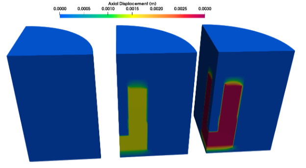
Figure 1: Displacement field prior the 30 Ȼ transient (left), at the beginning of the transient (middle) and after the transient (right).
The steps of modeling the 30 Ȼ transient are like the steps for 15 Ȼ test. Griffin was the main application which calculates the fission power, controls the time steps, and calls the BISON sub-application to calculate the temperature distributions as well as the displacement fields. Listing 1-6 include the key blocks that were unique for modeling the 30 Ȼ tests, in particular for modeling the second step of the transient.
Listing 1: Input block in Griffin main application to control the time step based on the number of iterations and power evolution.
[Executioner]
  [TimeStepper]
    type = IterationAdaptiveDT
    dt = 1e-2
    timestep_limiting_postprocessor = power_driven_dt
  []
[]The upper limit for the current time step length between 755 seconds and 900 s is determined by the Postprocessor “power_driven_dt” which is defined in Listing 2.
Listing 2: Input block which defines the postprocessor power_driven_dt, which is utilized to control the time step size.
[Postprocessors]
  [power_driven_dt]
    type = ParsedPostprocessor
    pp_names = 'integrated_power power_limited_dt'
    constant_names = 'low_pw hi_pw ldt hdt'
    constant_expressions = '754 760 1 1'
    function = 'pddt:=if(integrated_power<low_pw,ldt,if(integrated_power>hi_pw,hdt,ldt+(hdt-ldt)*(integrated_power-low_pw)/(hi_pw-low_pw)));
                min(power_limited_dt,pddt)'
  []
[]These Postprocessors help make it possible to control the time step size during the insertion of the second 15 Ȼ.
Listing 3: Input blocks to transfer the displacement positions between BISON and Griffin for modeling the second step of the experiment.
[Transfers]
  [from_bison_disp]
    type = MultiAppPostprocessorTransfer
    from_multi_app = bison
    from_postprocessor = disp_old_origin
    to_postprocessor = disp_old_medium
    reduction_type = average
  []

  [to_bison_disp]
    type = MultiAppPostprocessorTransfer
    to_multi_app = bison
    from_postprocessor = disp_old_medium
    to_postprocessor = disp_old_target
  []
[]As an essential part of the control approach used for the second stage of reactivity insertion, the shift value of the radial reflector at the last time step must be accessible by the control algorithm. To simplify the setup which already includes fixed point iterations between multiple solves, this value is transferred to the main application and transferred back into another Postprocessor. The input blocks for the three postprocessor, in which the disp_old_medium is defined in the Griffin input and the other two defined in BISON input are included in the Listing 4.
Listing 4: Input blocks for defining the Postprocessors in transferring the displacements.
[Postprocessors]
  [disp_old_origin]
    type = FunctionValuePostprocessor
    function = ref_mov
    execute_on = 'initial timestep_end'
  []

  [disp_old_target]
    type = Receiver
    default = '${fparse reflector_disp_init+reflector_disp_increment_1}'
  []
[]Listing 5: Input blocks that define the function “ref_mov” in Listing 4.
[Functions]
  [ref_mov]
    type = ParsedFunction
    symbol_names = 'reflector_disp_0       reflector_disp_increment_1         reflector_disp_increment_2         rdi2_scale_factor t_first_15c_insertion  t_start_power_monitoring existing_reflector_disp unit_increment_fraction pw          pw_ref'
    symbol_values = '${reflector_disp_init} ${reflector_disp_increment_1}      ${reflector_disp_increment_2}      1.1               0.5                    697                      disp_old_target         0.09                    total_power 750'
    expression = 'reflector_disp_15c:=reflector_disp_0+reflector_disp_increment_1;
                    if(t<0,reflector_disp_0,
                          if(t<t_first_15c_insertion,reflector_disp_0+reflector_disp_increment_1/t_first_15c_insertion*t,
                                                      if(t<t_start_power_monitoring,reflector_disp_15c,
                                                                                    if(pw<pw_ref&existing_reflector_disp<reflector_disp_15c+reflector_disp_increment_2*rdi2_scale_factor,existing_reflector_disp+reflector_disp_increment_2*unit_increment_fraction,
                                                                                                                                                                                         existing_reflector_disp))))'
  []
[]The definitions for each of the variables and symbols were listed in Table 1 below:
Table 1: Definition of the constant values in the ref_mov function that used to describe the radial reflector movement in the second step of the 30 Ȼ test.
| Constant Name | Description |
|---|---|
reflector_disp_init | initial reflector displacement at the start of the test |
reflector_disp_increment_1 | increment of the reflector displacement at the first 15 Ȼ insertion |
reflector_disp_increment_2 | nominal total increment of the reflector displacement at the second 15 Ȼ insertion |
rdi2_scale_factor | scale factor for the second 15 Ȼ insertion that is tuned to achieve ~150 second power maintenance |
t_first_15c_insertion | time at which the first 15 Ȼ insertion is completed (starting from t = 0) |
t_start_power_monitoring | time at which the power starts to be monitored for power maintenance during the second 15 Ȼ insertion |
existing_reflector_disp | existing reflector displacement recorded by a post-processor |
unit_increment_fraction | fraction of the nominal total increment of the reflector displacement at the second 15 Ȼ insertion that is applied during each insertion step; the value is obtained by tuning to limit the power jump during each step of the insertion |
pw | total current power of the microreactor |
pw_ref | reference power for power maintenance during the second 15 Ȼ insertion |
The Function “Ref_mov” has also been used to prescribe the boundary condition for generating the displacement mesh as its input block is included in Listing 6.
Listing 6: Input block for defining the BISON boundary condition at the bottom surface the comet
[BCs]
  [BottomSSFixZ]
    type = FunctionDirichletBC
    variable = disp_z
    boundary = 'ss_bot'
    function = ref_mov
  []
[]Simulation Results
Figure 2 compares the total power calculated by Griffin with the measured total power from neutron detectors. Overall, the calculated power history matches experimental history well. The multiphysics model predicted the power peaking accurately. In experiment, the experiment achieved a peak power of 3.65 kW, or a quarter-core power of 913 W, and the numerical model calculated a peak quarter-core power of 913.5 W. After the peaking, when the quarter-core power drops to 750 W, the automatic reactivity insertion mechanism was proved to be able to maintain the quarter-core power within the 750~760 W window for approximately 150 seconds, which agrees also well with the experimental data. Finally, in the absence of additional reactivity insertion, reactor power started to decrease continuously. Figure 2 also shows that the multiphysics model predicts the power decreasing rate correctly.
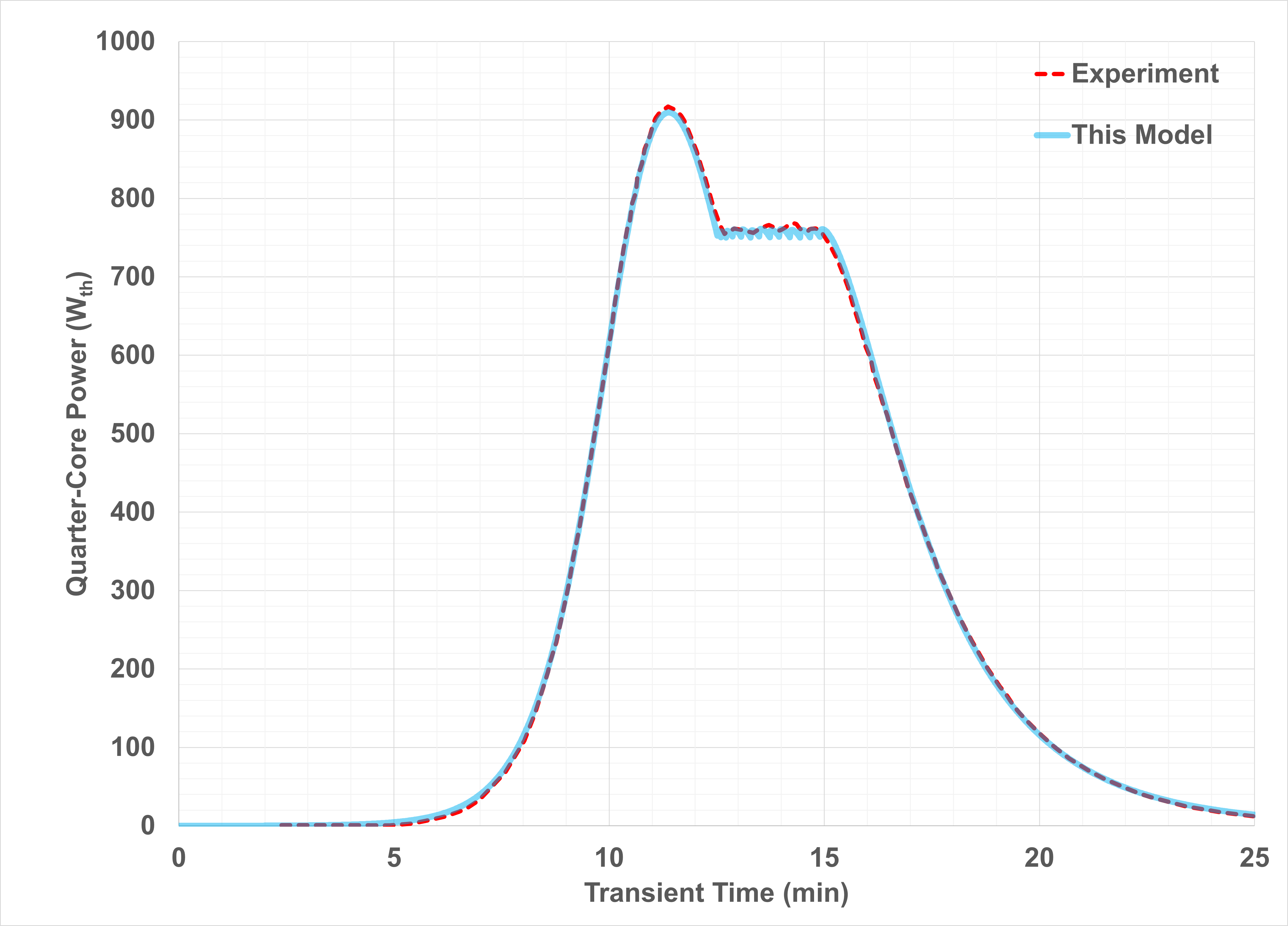
Figure 2: Predicted power evolution vs measurement (30 ₵ test)
References
- David I Poston, Marc A Gibson, Patrick R McClure, and Rene G Sanchez.
Results of the krusty warm critical experiments.
Nuclear Technology, 206(sup1):S78–S88, 2020.[BibTeX]
@article{Poston2020_1,
    author = "Poston, David I and Gibson, Marc A and McClure, Patrick R and Sanchez, Rene G",
    title = "Results of the KRUSTY warm critical experiments",
    journal = "Nuclear Technology",
    volume = "206",
    number = "sup1",
    pages = "S78--S88",
    year = "2020",
    publisher = "Taylor \\& Francis"
}
(microreactors/KRUSTY/Multiphysics_30C_RIT/KRUSTY_Griffin_SN23_NA23_CMFD_TR.i)
################################################################################
## NEAMS Micro-Reactor Application Driver                                     ##
## KRUSTY Multiphysics 30-Cent Reactivity Insertion                           ##
## Griffin neutronics input file (Main App)                                   ##
## DFEM-SN (2, 3) NA = 3 with CMFD acceleration                               ##
################################################################################

max_power_increment = 10
min_dt = 0.01
mesh_file = '../gold/MESH/Griffin_mesh.e'

[Mesh]
  [fmg]
    # This simulation relies on the steady state KRUSTY simulation
    # with zero reflector insertion as the initial condition
    # Refer to the mesh setup in the steady state simulation
    type = FileMeshGenerator
    file = ${mesh_file}
    # file = 'griffin_mesh.cpr'
  []
  [rot]
    type = TransformGenerator
    input = fmg
    transform = ROTATE
    vector_value = '-90 0 0'
  []
  [id]
    type=SubdomainExtraElementIDGenerator
    input = rot
    subdomains = '1 2 3 4 5 6
                  64 71 72 73
                  8 9 10 11
                  12 1212
                  13 14 15 16 17 18 19
                  20 21 22 23 24
                  2081 2091 2101 2111 2121 2131 2141
                  2082 2092 2102 2112 2122 2132 2142
                  3081 3091 3101 3111 3121 3131 3141
                  3082 3092 3102 3112 3122 3132 3142
                  4081 4091 4101 4111 4121 4131 4141
                  4082 4092 4102 4112 4122 4132 4142'

    extra_element_id_names = 'material_id'
    extra_element_ids ='99 17 11 15 70 18
                        99 6 6 60
                        8 5 10 40
                        51 52
                        4 20 18 40 50 14 13
                        6 7 12 11 9
                        300  310  320  330  340  350  360
                        301  311  321  331  341  351  361
                        202  212  222  232  242  252  262
                        203  213  223  233  243  253  263
                        104  114  124  134  144  154  164
                        105  115  125  135  145  155  165'
  []
  [coarse_mesh]
    type = GeneratedMeshGenerator
    dim= 3
    nx = 20   # about 2 cm may need to adjust
    ny = 20   # about 2 cm may need to adjust
    nz = 40   # about 5 cm may need to adjust to test convergence or performance
    xmin = -2
    xmax =  52
    ymin = -2
    ymax =  52
    zmin = -1
    zmax =  135
  []
  [assign_coarse_id]
    type = CoarseMeshExtraElementIDGenerator
    input = id
    coarse_mesh = coarse_mesh
    extra_element_id_name = coarse_element_id
  []
  parallel_type = distributed
  displacements = 'disp_x disp_y disp_z'
[]

# No initial value needed as this is restarting
[AuxVariables]
  [Tf]
    order = CONSTANT
    family = MONOMIAL
  []
  [Ts]
    order = CONSTANT
    family = MONOMIAL
  []
  [disp_x]
  []
  [disp_y]
  []
  [disp_z]
  []
[]

[TransportSystems]
  particle = neutron
  equation_type = transient
  G = 22
  VacuumBoundary = '9527 9528 9529'
  ReflectingBoundary = '1982 1983'

  [sn]
    scheme = DFEM-SN
    family = MONOMIAL
    order = FIRST
    AQtype = Gauss-Chebyshev
    NPolar = 2
    NAzmthl = 3

    NA = 3
    sweep_type = asynchronous_parallel_sweeper
    using_array_variable = true
    collapse_scattering = true
    n_delay_groups = 6

    use_displaced_mesh = true
  []
[]

[PowerDensity]
  power = 0.01
  power_density_variable = power_density
  integrated_power_postprocessor = integrated_power
[]

[Postprocessors]
  [_dt]
    type = TimestepSize
    execute_on = 'initial timestep_end'
  []
  [power_increment]
    type = ChangeOverTimePostprocessor
    postprocessor = integrated_power
    change_with_respect_to_initial = false
    execute_on = 'initial timestep_end'
    take_absolute_value = true
  []
  # A postprocessor to limit the timestep based on the absolute power increment
  [power_limited_dt]
    type = ParsedPostprocessor
    pp_names = 'power_increment _dt'
    constant_names = 'max_increment min_dt'
    constant_expressions = '${max_power_increment} ${min_dt}'
    function = 't_lim:=_dt*max_increment/power_increment;
                max(min_dt,t_lim)'
  []
  [power_driven_dt]
    type = ParsedPostprocessor
    pp_names = 'integrated_power power_limited_dt'
    constant_names = 'low_pw hi_pw ldt hdt'
    constant_expressions = '754 760 1 1'
    function = 'pddt:=if(integrated_power<low_pw,ldt,if(integrated_power>hi_pw,hdt,ldt+(hdt-ldt)*(integrated_power-low_pw)/(hi_pw-low_pw)));
                min(power_limited_dt,pddt)'
  []
  [disp_old_medium]
    type = Receiver
    default = 0.0 # should be the same as `reflector_disp_init` in subapp
  []
[]

[Executioner]
  type = TransientSweepUpdate
  verbose = true

  richardson_abs_tol = 1e-6
  richardson_rel_tol = 1e-15

  richardson_max_its = 30
  inner_solve_type = GMRes
  max_inner_its = 100

  cmfd_acceleration = true
  coarse_element_id = coarse_element_id
  max_diffusion_coefficient = 10.0
  diffusion_prec_type = lu
  prolongation_type = multiplicative

  end_time = 7200
  dtmin = ${min_dt}
  dtmax = 10

  [TimeStepper]
    type = IterationAdaptiveDT
    dt = 1e-2
    timestep_limiting_postprocessor = power_driven_dt
  []
[]

[Materials]
  [all]
    type = CoupledFeedbackMatIDNeutronicsMaterial
    block = '1 2 3 4 5 6
         64 71 72 73
         8 9 10 11
         12 1212
         13 14 15 16 17 18 19
         20 21 22 23 24
         2081 2091 2101 2111 2121 2131 2141
         2082 2092 2102 2112 2122 2132 2142
         3081 3091 3101 3111 3121 3131 3141
         3082 3092 3102 3112 3122 3132 3142
         4081 4091 4101 4111 4121 4131 4141
         4082 4092 4102 4112 4122 4132 4142'
    library_file ='../Neutronics/Serp_hbrid_reflector_updated.xml'
    library_name ='krusty_serpent_ANL_endf70_g22'
    isotopes = 'pseudo'
    densities = '1.0'
    grid_names = 'Tfuel Tsteel'
    grid_variables = 'Tf Ts'
    plus = 1
    is_meter = true
    dbgmat = false

    displacements = 'disp_x disp_y disp_z'
  []
[]

[Outputs]
  csv = true
  exodus = true
  [pgraph]
    type = PerfGraphOutput
    level = 2
  []
  [cp]
    type = Checkpoint
    num_files = 2
  []
[]

[MultiApps]
  [bison]
    type = TransientMultiApp
    input_files = KRUSTY_BISON_THERMOMECHANICS_TR.i
    execute_on = 'initial timestep_end'
  []
[]

[Transfers]
  [to_sub_power_density]
    type = MultiAppGeneralFieldShapeEvaluationTransfer
    to_multi_app = bison
    source_variable = power_density
    variable = power_density
    from_postprocessors_to_be_preserved = integrated_power
    to_postprocessors_to_be_preserved = total_power
    execute_on = 'timestep_end'
  []
  [from_sub_tempf]
    type = MultiAppGeneralFieldShapeEvaluationTransfer
    from_multi_app = bison
    variable = Tf
    source_variable = Tfuel
  []
  [from_sub_tempm]
    type = MultiAppGeneralFieldShapeEvaluationTransfer
    from_multi_app = bison
    variable = Ts
    source_variable = Tsteel
  []
  [from_sub_disp_x]
    type = MultiAppGeneralFieldShapeEvaluationTransfer
    from_multi_app = bison
    variable = disp_x
    source_variable = disp_x
  []
  [from_sub_disp_y]
    type = MultiAppGeneralFieldShapeEvaluationTransfer
    from_multi_app = bison
    variable = disp_y
    source_variable = disp_y
  []
  [from_sub_disp_z]
    type = MultiAppGeneralFieldShapeEvaluationTransfer
    from_multi_app = bison
    variable = disp_z
    source_variable = disp_z
  []
  ## transfer and store the reflector displacement at the main app to facilitate the control mechanism
  [from_bison_disp]
    type = MultiAppPostprocessorTransfer
    from_multi_app = bison
    from_postprocessor = disp_old_origin
    to_postprocessor = disp_old_medium
    reduction_type = average
  []
  [to_bison_disp]
    type = MultiAppPostprocessorTransfer
    to_multi_app = bison
    from_postprocessor = disp_old_medium
    to_postprocessor = disp_old_target
  []
[]

[UserObjects]
  [ss]
    type = TransportSolutionVectorFile
    transport_system = sn
    writing = false
    execute_on = initial
  []
[]
(microreactors/KRUSTY/Multiphysics_30C_RIT/KRUSTY_BISON_THERMOMECHANICS_TR.i)
################################################################################
## NEAMS Micro-Reactor Application Driver                                     ##
## KRUSTY Multiphysics 30-Cent Reactivity Insertion                           ##
## BISON thermomechanics main input file (Child App)                          ##
## Heat Conduction, Thermal Expansion, Thermal Stress                         ##
################################################################################

!include ../Multiphysics_SS/KRUSTY_BISON_PARAMS.i

restart_cp_file = '../Multiphysics_SS/KRUSTY_Griffin_SN23_NA23_CMFD_out_bison0_checkpoint_cp/LATEST'

reflector_disp_init = 0
reflector_disp_increment_1 = 1.447e-3 # Corresponding to the first 15 cents reactivity insertion
reflector_disp_increment_2 = 1.400e-3 # Corresponding to the nominal second 15 cents reactivity insertion

[GlobalParams]
  temperature = temp
  displacements = 'disp_x disp_y disp_z'
  stress_free_temperature = 298
[]

[Problem]
  type = ReferenceResidualProblem
  reference_vector = 'ref'
  extra_tag_vectors = 'ref'
  group_variables = 'disp_x disp_y disp_z'

  restart_file_base = ${restart_cp_file}
[]

[Mesh]
  file = ${restart_cp_file}
  parallel_type = distributed
[]

# No initial value needed as this is restarting
# For both Variables and AuxVariables
[Variables]
  # We have two temperature variables, one for the fuel and one for the non-fuel
  # This is to allow discontinuity on the fuel surface so that the insulation
  # can be better simulated using `InterfaceKernels`
  [temp]
    block = ${nonfuel_all}
  []
  [temp_f]
    block = ${fuel_all}
  []
[]

[AuxVariables]
  [power_density]
    block = ${fuel_all}
    family = L2_LAGRANGE
    order = FIRST
  []
  [Tfuel]
    order = CONSTANT
    family = MONOMIAL
  []
  [Tsteel]
    order = CONSTANT
    family = MONOMIAL
  []
  [external_power]
  []
  [hp_temp_aux]
  []
[]

[UserObjects]
  [temp_f_avg]
    type = LayeredAverage
    variable = temp_f
    direction = z
    num_layers = 100
    block = ${fuel_all}
  []
  [temp_s_avg]
    type = LayeredAverage
    variable = temp
    direction = z
    num_layers = 100
    block = '${ss_all} 998'
  []
[]

[AuxKernels]
  [assign_tfuel_f]
    type = NormalizationAux
    variable = Tfuel
    source_variable = temp_f
    execute_on = 'timestep_end'
    block = ${fuel_all}
  []
  [assign_tfuel_nf]
    type = SpatialUserObjectAux
    variable = Tfuel
    user_object = temp_f_avg
    execute_on = 'timestep_end'
    block = ${nonfuel_all}
  []
  [assign_tsteel_s]
    type = NormalizationAux
    variable = Tsteel
    source_variable = temp
    execute_on = 'timestep_end'
    block = '${ss_all} 998'
  []
  [assign_tsteel_ns]
    type = SpatialUserObjectAux
    variable = Tsteel
    user_object = temp_s_avg
    execute_on = 'timestep_end'
    block = ${non_ss_998_all}
  []
[]

# A small materials block for thin layers
[Materials]
  [thermal_cond_mli]
    type = GenericConstantMaterial
    prop_names = 'thermal_conductivity_mli'
    prop_values = '${hp_mli_cond}'
    boundary = 'fuel_top fuel_bottom fuel_side_1'
  []
  [thermal_cond_center]
    type = GenericConstantMaterial
    prop_names = 'thermal_conductivity_center'
    prop_values = '0.20'
    boundary = 'fuel_inside'
  []
  [thermal_cond_other]
    type = GenericConstantMaterial
    prop_names = 'thermal_conductivity_other'
    prop_values = '15.0'
    boundary = 'fuel_side_2'
  []
[]

[InterfaceKernels]
  [fuel_ref]
    type = ThinLayerHeatTransfer
    thermal_conductivity = thermal_conductivity_mli
    thickness = 0.005
    variable = temp_f
    neighbor_var = temp
    boundary = 'fuel_top fuel_bottom fuel_side_1'
  []
  [fuel_center]
    type = ThinLayerHeatTransfer
    thermal_conductivity = thermal_conductivity_center
    thickness = 0.001
    variable = temp_f
    neighbor_var = temp
    boundary = 'fuel_inside'
  []
  [fuel_other]
    type = ThinLayerHeatTransfer
    thermal_conductivity = thermal_conductivity_other
    thickness = 0.0001
    variable = temp_f
    neighbor_var = temp
    boundary = 'fuel_side_2'
  []
[]

[Kernels]
  [heat]
    type = HeatConduction
    variable = temp
    extra_vector_tags = 'ref'
    block = ${nonfuel_all}
  []
  [heat_f]
    type = HeatConduction
    variable = temp_f
    extra_vector_tags = 'ref'
    block = ${fuel_all}
  []
  [heat_ie]
    type = HeatConductionTimeDerivative
    variable = temp
    extra_vector_tags = 'ref'
    block = ${nonfuel_all}
  []
  [heat_ie_f]
    type = HeatConductionTimeDerivative
    variable = temp_f
    extra_vector_tags = 'ref'
    block = ${fuel_all}
  []
  [heatsource]
    type = CoupledForce
    variable = temp_f
    block = ${fuel_all}
    v = power_density
    extra_vector_tags = 'ref'
  []

  # These diffusion kernels evenly disperse the displacement across the void
  [diff_x]
    type = MatDiffusion
    block = '${air_all} ${hp_fuel_gap_all} ${hp_mli_all}'
    variable = disp_x
    diffusivity = 1e5
    extra_vector_tags = 'ref'
  []
  [diff_y]
    type = MatDiffusion
    block = '${air_all} ${hp_fuel_gap_all} ${hp_mli_all}'
    variable = disp_y
    diffusivity = 1e5
    extra_vector_tags = 'ref'
  []
  [diff_z]
    type = MatDiffusion
    block = '${air_all} ${hp_fuel_gap_all} ${hp_mli_all}'
    variable = disp_z
    diffusivity = 1e5
    extra_vector_tags = 'ref'
  []
[]

# We create variables separately because Air density requires displacement variables
# but the solid mechanics equations would only create these variables on blocks we solve equations
# for displacements on
# Note: not creating the displacement variables on the air blocks would likely be more efficient
[Variables]
  [disp_x]
  []
  [disp_y]
  []
  [disp_z]
  []
[]

[Physics/SolidMechanics/QuasiStatic]
  add_variables = false
  [mech_parts_fuel]
    block = '${fuel_all}'
    temperature = temp_f
    strain = SMALL # Small strain should work, but finite may have better performance
    add_variables = true
    eigenstrain_names = 'thermal_strain'
    generate_output = 'vonmises_stress strain_xx strain_yy strain_zz stress_xx stress_yy stress_zz hydrostatic_stress'
    extra_vector_tags = 'ref'
    use_automatic_differentiation = false
  []
  [mech_parts_non_fuel]
    block = '${nonfuel_mech}'
    strain = SMALL # Small strain should work, but finite may have better performance
    add_variables = true
    eigenstrain_names = 'thermal_strain'
    generate_output = 'vonmises_stress strain_xx strain_yy strain_zz stress_xx stress_yy stress_zz hydrostatic_stress'
    extra_vector_tags = 'ref'
    use_automatic_differentiation = false
  []
[]

[Materials]
  [stress]
    type = ComputeLinearElasticStress
    block = '${no_void} ${hp_all}'
  []

  [UMoDens]
    type = Density
    block = ${fuel_all}
    density = ${umo_dens}
  []
  [UMoMech]
    type = ComputeIsotropicElasticityTensor
    block = ${fuel_all}
    youngs_modulus = ${umo_ym}
    poissons_ratio = ${umo_pr}
  []
  [UMoExp]
    type = U10MoThermalExpansionEigenstrain
    block = ${fuel_all}
    temperature = temp_f
    eigenstrain_name = thermal_strain
    stress_free_temperature = 298
    model_option = Rest
  []
  [fission_density]
    type = GenericConstantMaterial
    prop_names = 'fission_density'
    prop_values = 0.0
    block = ${fuel_all}
  []
  [UMo_thermal]
    type = HeatConductionMaterial
    block = ${fuel_all}
    temp = temp_f
    specific_heat_temperature_function = umo_heat_cap
    thermal_conductivity_temperature_function = umo_tc
  []
  [BeODens]
    type = Density
    block = ${beo_all}
    density = ${beo_dens}
  []
  [BeOMech]
    type = BeOElasticityTensor
    temperature = temp
    block = ${beo_all}
    porosity = 0.01
  []

  [BeOExp]
    type = BeOThermalExpansionEigenstrain
    eigenstrain_name = thermal_strain
    stress_free_temperature = 298
    temperature = temp
    block = ${beo_all}
  []
  [BeO_thermal]
    type = BeOThermal
    block = ${beo_all}
    fluence_conversion_factor = 1
    temperature = temp
    outputs = all
    porosity = 0
    fast_neutron_fluence = 0
  []
  [AirDens]
    type = Density
    block = ${air_all}
    density = ${air_dens}
  []
  [AirTherm]
    type = HeatConductionMaterial
    block = ${air_all}
    thermal_conductivity = ${air_cond}
    specific_heat = ${air_sph}
  []

  # HP Fuel Coupling Material
  # Note HP was replaced with steel rods
  [HPFDens]
    type = Density
    block = ${hp_fuel_gap_names}
    density = ${hp_fuel_couple_dens}
  []
  [HPFTherm]
    type = HeatConductionMaterial
    block = ${hp_fuel_gap_names}
    thermal_conductivity = ${hp_fuel_couple_cond}
    specific_heat = ${hp_fuel_couple_sph}
  []

  [HPMLIDens]
    type = Density
    block = ${hp_mli_names}
    density = ${hp_mli_dens}
  []
  [HPMLIherm]
    type = HeatConductionMaterial
    block = ${hp_mli_names}
    thermal_conductivity = ${hp_mli_cond}
    specific_heat = ${hp_mli_sph}
  []

  #Stainless Steel; Assuming all the stuctures are SS316
  [SS316Dens]
    type = Density
    block = '${ss_all} ${hp_all}'
    density = ${ss_dens}
  []
  [SS316Mech]
    type = SS316ElasticityTensor
    elastic_constants_model = legacy_ifr
    block = '${ss_all} ${hp_all}'
    temperature = temp
  []
  [SS316Exp]
    type = SS316ThermalExpansionEigenstrain
    block = '${ss_all} ${hp_all}'
    temperature = temp
    eigenstrain_name = thermal_strain
    stress_free_temperature = 298
  []

  [SS316Therm]
    type = SS316Thermal
    block = '${ss_all} ${hp_all}'
    temperature = temp
  []

  #Aluminium
  [Al6061Dens]
    type = Density
    block = ${Al_all}
    density = ${al_dens}
  []
  [Al6061Mech]
    type = Al6061ElasticityTensor
    block = ${Al_all}
    temperature = temp
    youngs_modulus_model = Kaufman
  []
  [Al6061Exp]
    type = Al6061ThermalExpansionEigenstrain
    block = ${Al_all}
    temperature = temp
    eigenstrain_name = thermal_strain
    stress_free_temperature = 298
  []

  [Al6061Therm]
    type = SS316Thermal
    block = ${Al_all}
    temperature = temp
  []

  #Natural Boron Carbide (Not enriched boron)
  [B4CDens]
    type = Density
    block = ${b4c_all}
    density = ${b4c_dens}
  []
  [B4CMech]
    type = ComputeIsotropicElasticityTensor
    block = ${b4c_all}
    youngs_modulus = ${b4c_ym}
    poissons_ratio = ${b4c_pr}
  []
  [B4CExp]
    type = ComputeThermalExpansionEigenstrain
    block = ${b4c_all}
    thermal_expansion_coeff = ${b4c_exp}
    eigenstrain_name = thermal_strain
  []
  [B4CTherm]
    type = HeatConductionMaterial
    block = ${b4c_all}
    thermal_conductivity = ${b4c_cond}
    specific_heat = ${b4c_sph}
  []

  #Pure Beryllium
  [BeDens]
    type = Density
    block = ${Be_all}
    density = ${Be_dens}
  []
  [BeMech]
    type = ComputeIsotropicElasticityTensor
    block = ${Be_all}
    youngs_modulus = ${Be_ym}
    poissons_ratio = ${Be_pr}
  []
  [BeExp]
    type = ComputeThermalExpansionEigenstrain
    block = ${Be_all}
    thermal_expansion_coeff = ${Be_exp}
    eigenstrain_name = thermal_strain
  []
  [BeTherm]
    type = HeatConductionMaterial
    block = ${Be_all}
    thermal_conductivity = ${Be_cond}
    specific_heat = ${Be_sph}
  []

[]

[Functions]
  [umo_heat_cap]
    # https://doi.org/10.1016/S0022-3697(00)00219-5.
    type = ParsedFunction
    expression = 'M:=210.4243/1000;
                  dHdT:=20.8+1.174e-2*t+0.4715e5/t/t;
                  dHdT/M'
  []
  [umo_tc]
    type = ParsedFunction
    expression = '0.606+0.0351*t'
  []
  # The function that controls the displacement of the reflector
  # Used to control the reactivity insertion
  [ref_mov]
      type = ParsedFunction
      symbol_names =  'reflector_disp_0       reflector_disp_increment_1         reflector_disp_increment_2         rdi2_scale_factor t_first_15c_insertion  t_start_power_monitoring existing_reflector_disp unit_increment_fraction pw          pw_ref'
      symbol_values = '${reflector_disp_init} ${reflector_disp_increment_1}      ${reflector_disp_increment_2}      1.1               0.5                    697                      disp_old_target         0.09                    total_power 750'
      expression = 'reflector_disp_15c:=reflector_disp_0+reflector_disp_increment_1;
                    if(t<0,reflector_disp_0,
                          if(t<t_first_15c_insertion,reflector_disp_0+reflector_disp_increment_1/t_first_15c_insertion*t,
                                                      if(t<t_start_power_monitoring,reflector_disp_15c,
                                                                                    if(pw<pw_ref&existing_reflector_disp<reflector_disp_15c+reflector_disp_increment_2*rdi2_scale_factor,existing_reflector_disp+reflector_disp_increment_2*unit_increment_fraction,
                                                                                                                                                                                         existing_reflector_disp))))'
  []
[]

[BCs]
  [OuterWall]
    type = ConvectiveHeatFluxBC
    variable = temp
    boundary = '9531 Core_bottom Core_outer_boundary' #outer wall sideset
    heat_transfer_coefficient = 5 # free convection in dry air W/m2/K
    T_infinity = 300 # room temperature
  []
  [BottomFixZ]
    type = DirichletBC
    variable = disp_z
    boundary = 'Core_bottom'
    value = 0.0
  []
  # The BC that controls the displacement of the reflector
  [BottomSSFixZ]
    type = FunctionDirichletBC
    variable = disp_z
    boundary = 'ss_bot'
    function = ref_mov
  []
  [TopFixZ]
    type = DirichletBC
    variable = disp_z
    boundary = 'Core_top'
    value = 0.0
  []

  [MirrorOneFixX]
    type = DirichletBC
    variable = disp_y
    boundary = 'Mirror_Y_surf'
    value = 0.0
  []
  [MirrorOneFixY]
    type = DirichletBC
    variable = disp_x
    boundary = 'Mirror_X_surf'
    value = 0.0
  []
[]

[Preconditioning]
  [SMP]
    type = SMP
    full = true
  []
[]

[Executioner]
  type = Transient

  petsc_options_iname = '-pc_type -pc_factor_mat_solver_package -ksp_gmres_restart'
  petsc_options_value = 'lu       superlu_dist                  51'
  line_search = 'none'

  nl_abs_tol = 1e-7
  nl_rel_tol = 1e-7
  l_tol = 1e-4
  l_max_its = 25
  automatic_scaling = true
  compute_scaling_once = false

  start_time = 0
  end_time = 7200
  # Let main app to control the time step
  dt = 10
[]

[Postprocessors]
  [_dt]
    type = TimestepSize
  []
  [total_power]
    type = ElementIntegralVariablePostprocessor
    block = ${fuel_all}
    variable = power_density
    execute_on = 'initial TIMESTEP_END transfer'
  []
  [avg_fuel_temp]
    type = ElementAverageValue
    block = ${fuel_all}
    variable = temp_f
    execute_on = 'initial TIMESTEP_END'
  []
  [max_fuel_temp]
    type = ElementExtremeValue
    block = ${fuel_all}
    variable = temp_f
    value_type = max
    execute_on = 'initial TIMESTEP_END'
  []
  [min_fuel_temp]
    type = ElementExtremeValue
    block = ${fuel_all}
    variable = temp_f
    value_type = min
    execute_on = 'initial TIMESTEP_END'
  []
  [avg_nonfuel_temp]
    type = ElementAverageValue
    block = ${nonfuel_all}
    variable = temp
    execute_on = 'initial TIMESTEP_END'
  []
  [max_nonfuel_temp]
    type = ElementExtremeValue
    block = ${nonfuel_all}
    variable = temp
    value_type = max
    execute_on = 'initial TIMESTEP_END'
  []
  [min_nonfuel_temp]
    type = ElementExtremeValue
    block = ${nonfuel_all}
    variable = temp
    value_type = min
    execute_on = 'initial TIMESTEP_END'
  []
  [avg_fuel_cond]
    type = ElementAverageValue
    block = ${fuel_all}
    variable = thermal_conductivity
    execute_on = 'initial TIMESTEP_END'
  []
  [fuel_volume]
    type = VolumePostprocessor
    block = ${fuel_all}
    use_displaced_mesh = true
    execute_on = 'initial TIMESTEP_END'
  []
  [power_density_avg_everywhere]
    type = ElementAverageValue
    variable = power_density
    block = ${fuel_all}
  []
  [power_density_avg]
    type = ElementAverageValue
    variable = power_density
    block = ${fuel_all}
  []
  [power_density_max]
    type = ElementExtremeValue
    variable = power_density
    block = ${fuel_all}
  []
  [power_density_min]
    type = ElementExtremeValue
    variable = power_density
    block = ${fuel_all}
    value_type = min
  []
  [disp_old_origin]
    type = FunctionValuePostprocessor
    function = ref_mov
    execute_on = 'initial timestep_end'
  []
  [disp_old_target]
    type = Receiver
    default = ${fparse reflector_disp_init+reflector_disp_increment_1}
  []
[]

[Outputs]
  csv = true
  [exodus]
    type = Exodus
    enable = false
  []
  [checkpoint]
    type = Checkpoint
    enable = false
  []
  perf_graph = true
  color = true
[]