Meshing Terminology
Before proceeding in this tutorial, we briefly define some terminology, limiting discussion to the spatial domain for simplicity:
Finite Element Method (FEM)
A numerical technique to solve PDEs which first requires that the spatial domain be divided into a mesh consisting of a finite number of discretized pieces. (FEM is one of the foundations of the MOOSE framework.)
Mesh
A set of points connected to form a network which discretize a geometry into discrete elements.
An example of a unit pin cell mesh is given in Figure 1.
Node
A coordinate point in space, connected to one or more elements, which will be used along with other nodes to define element shape.
Nodes are highlighted as small circles in Figure 1. Nodes specify the vertices of linear triangular and quadrilateral elements.
Finite Element (or simply Element)
An ordered grouping of nodes that defines the boundaries of a piece of the spatial domain. A typical first order 2D element has 3 (triangle) or 4 (quadrilateral) nodes. Straight lines connect the nodes to form the element shape. In 3D, typical elements have 6 (triangular prism), 8 (hexahedron), 4 (tetrahedron) or 5 (pyramid) nodes. The full set of elements comprises the mesh which approximates the geometry. Basis functions from the FEM are defined on each element. Higher order elements may have additional nodes than those listed here, and may have curved geometries. A mesh can consist of different types of elements.
The mesh in Figure 1 has 48 unique elements (12 triangular in the center, and 36 quadrilateral).
Block (or Subdomain)
A grouping of elements which must have similar type and order. A mesh may have few or many blocks.
The mesh in Figure 1, has 4 unique blocks: 1 triangular element block (blue), and 3 quadrilateral element blocks (red, green, gray).
Nodeset
A grouping of nodes. Nodes can belong to more than one nodeset.
The mesh in Figure 1 has 3 nodesets, one pertaining to each sideset. Nodes within each nodeset link together to form the sideset edges.
Sideset
A grouping of element edges or faces (in 2D & 3D respectively) categorized by their owning surfaces or volumes. These are associated with elements and this association is determined by a normal direction to the edge or face. Edges or faces may belong to more than one sideset.
The mesh in Figure 1 has 3 unique sidesets (1 exterior sideset and 2 interior sidesets). No sideset was created between the blue and red blocks because these actually represent the same material (fuel) and therefore there is no material interface, information transfer, or boundary condition to apply here.
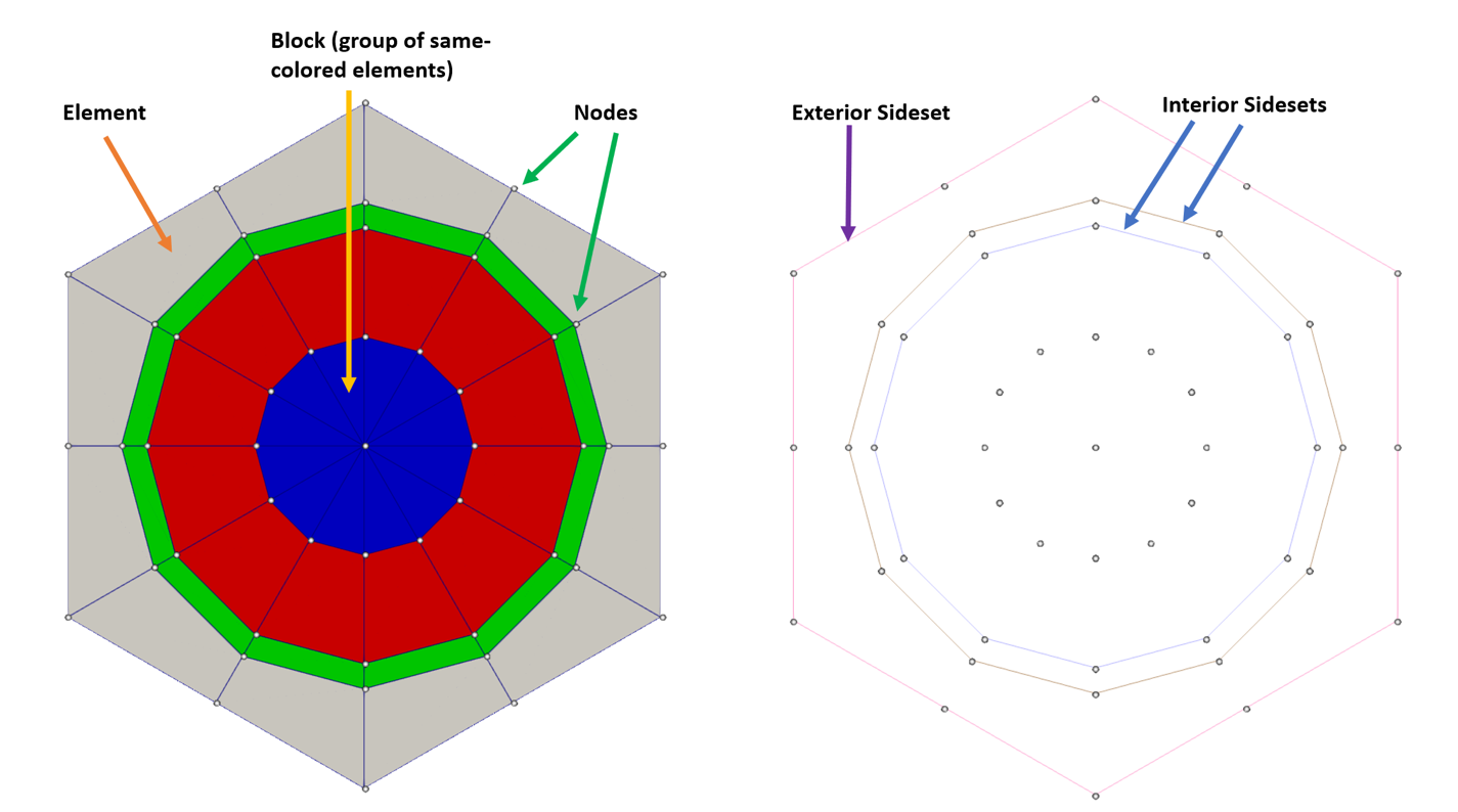
Figure 1: A unit pin cell mesh showing nodes, elements, blocks, and sidesets.