- inputThe input mesh to be modified. Note that this generator only works with PatternedHexMeshGenerator and its derived classes such as HexIDPatternedMeshGenerator.
C++ Type:MeshGeneratorName
Controllable:No
Description:The input mesh to be modified. Note that this generator only works with PatternedHexMeshGenerator and its derived classes such as HexIDPatternedMeshGenerator.
- input_mesh_external_boundaryThe external boundary of the input mesh.
C++ Type:BoundaryName
Controllable:No
Description:The external boundary of the input mesh.
- new_num_sectorNumber of sectors of each side for the new mesh.
C++ Type:unsigned int
Controllable:No
Description:Number of sectors of each side for the new mesh.
PatternedHexPeripheralModifier
This PatternedHexPeripheralModifier object removes the outmost layer of the input mesh and add a transition layer mesh to facilitate stitching.
Overview
This PatternedHexPeripheralModifier class utilizes FillBetweenPointVectorsTools to replace the outmost layer of the quad elements of the 2D hexagonal assembly mesh generated by PatternedHexMeshGenerator (or its derived class HexIDPatternedMeshGenerator) with a transition layer consisting of triangular elements so that the assembly mesh can have nodes on designated positions on the external boundary. This boundary modification facilitates the stitching of hexagonal assemblies which have different node numbers on their outer periphery due to differing numbers of interior pins and/or different azimuthal discretization.
Default Behavior of PatternedHexMeshGenerator and the Least Common Multiple Approach
When PatternedHexMeshGenerator is used to generate a hexagonal assembly mesh, the number of nodes on each hexagon side follows a pre-determined formula based on the pin cell meshes which comprise the assembly. These pin cell hexagonal meshes used by PatternedHexMeshGenerator must have a uniform even number of sectors per side (e.g., ) given by "num_sectors_per_side" in PolygonConcentricCircleMeshGenerator. If PatternedHexMeshGenerator creates a hexagonal bundle with () pins on each side of the outermost ring, there are sectors or nodes on each side of the hexagonal assembly mesh. If all the assemblies within a reactor core contain identical numbers of pins, it is straightforward to make assembly meshes stitchable with each other by using the same number for the azimuthal discretization of each pin cell. However, if a reactor core includes assemblies with different numbers of pins, must be wisely selected based on the least common multiple of ( is the assembly index) of all the assemblies involved. This approach may be practical in cases where two assembly types with different pin numbers are involved, as shown in the following table:
| Assm. #1 Number of pins per side | Assm. #1 Number of azimuthal intervals per sector | Assm. #1 Number of pins per side | Assm. #1 Number of azimuthal intervals per sector | Node Number on Assembly Side |
|---|---|---|---|---|
| 2 | 5 | 3 | 3 | 30 |
| 2 | 7 | 4 | 3 | 42 |
| 2 | 3 | 5 | 1 | 18 |
| 2 | 11 | 6 | 3 | 66 |
| 2 | 13 | 7 | 3 | 78 |
| 3 | 7 | 4 | 5 | 70 |
| 3 | 9 | 5 | 5 | 90 |
| 3 | 11 | 6 | 5 | 110 |
| 3 | 13 | 7 | 5 | 130 |
| 4 | 9 | 5 | 7 | 126 |
| 4 | 11 | 6 | 7 | 154 |
| 4 | 13 | 7 | 7 | 182 |
| 5 | 11 | 6 | 9 | 198 |
| 5 | 13 | 7 | 9 | 234 |
| 6 | 13 | 7 | 11 | 286 |
However, multiple different assemblies with unique numbers of pins are involved in a reactor core, the "num_sectors_per_side" (i.e., ) may be impractically large, as indicated in the following table:
| Assm. #1 | Assm. #1 | Assm. #2 | Assm. #2 | Assm. #3 | Assm. #3 | Node Number on Assembly Side |
|---|---|---|---|---|---|---|
| 2 | 35 | 3 | 21 | 4 | 15 | 210 |
| 2 | 15 | 3 | 9 | 5 | 5 | 90 |
| 2 | 55 | 3 | 33 | 6 | 15 | 330 |
| 2 | 21 | 4 | 9 | 5 | 7 | 126 |
| 2 | 77 | 4 | 33 | 6 | 21 | 462 |
| 2 | 33 | 5 | 11 | 6 | 9 | 198 |
| 3 | 63 | 4 | 45 | 5 | 35 | 630 |
| 3 | 77 | 4 | 55 | 6 | 35 | 770 |
| 3 | 99 | 5 | 55 | 6 | 45 | 990 |
| 4 | 99 | 5 | 77 | 6 | 63 | 1386 |
Modification of Peripheral Boundary to Allow Stitching
The PatternedHexPeripheralModifier class modifies assembly meshes so that assemblies with different number of pins can be stitched together without increasing the mesh fidelity to an impractically fine fidelity (as shown in the previous section). This mesh generator only works with the "input" mesh created by PatternedHexMeshGenerator. Users must specify the external boundary of the input assembly mesh through "input_mesh_external_boundary". Given this input, the mesh generator identifies and deletes the outmost layer of elements and uses the newly formed external boundary as one of the two vectors of boundary nodes needed by FillBetweenPointVectorsTools after symmetry reduction. In addition, uniformly distributed nodes are placed along the original external boundary of the mesh and defined as the second vector of boundary nodes needed by FillBetweenPointVectorsTools. The number of new boundary nodes is specified using "new_num_sector". Thus, the outmost layer of the assembly mesh can be replaced with a triangular element transition layer mesh that can be easily stitched with another transition layer mesh. An example of the assembly mesh modified by this mesh generator is shown in Figure 1
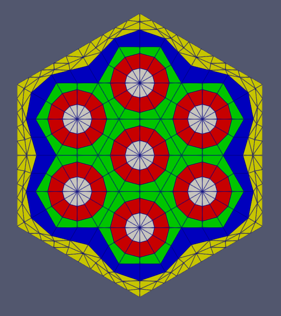
Figure 1: A schematic drawing of an example assembly mesh with transition layer as its outmost mesh layer.
Advantages
This mesh generator forces the number of nodes on a hexagonal mesh to match a user-specified input. This allows assemblies with different number of pins or azimuthal discretizations (and consequently different numbers of boundary nodes) to be stitched together without increasing the mesh density to an unreasonable level.
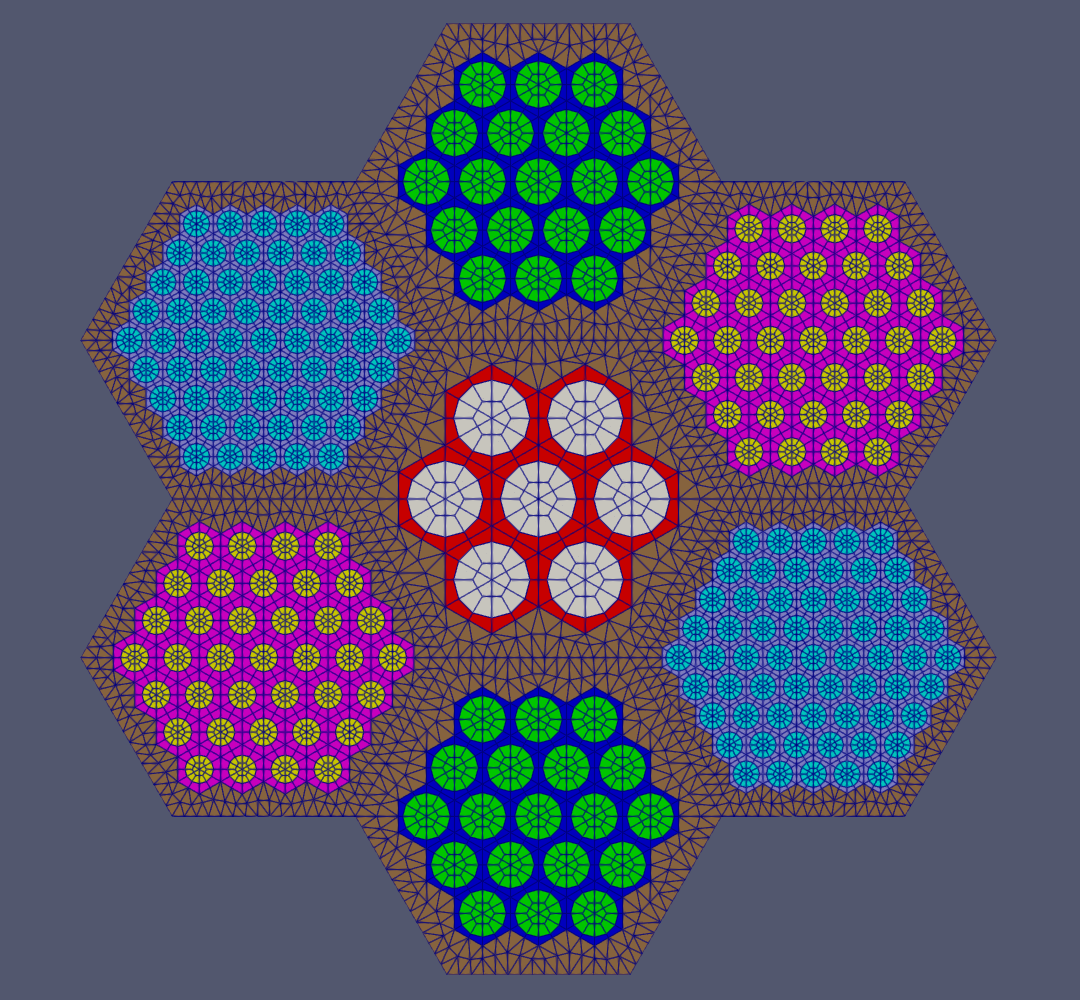
Figure 2: A schematic drawing showing a virtual core design with assemblies including 7, 19, 37 and 61 pins.
Figure 2 illustrates a core comprising four types of assemblies. This mesh generator's functionality was leveraged to force a common mesh density on each hexagonal assembly side (16 nodes on each assembly side) so that the assemblies can be easily stitched. In the absence of this mesh generator, the least common multiple approach would require 631 nodes on each assembly side as shown in Figure 3. The mesh density would be increased dramatically just to ensure stitchability, showing the prominent advantage of using this mesh generator instead of the least common multiple approach.
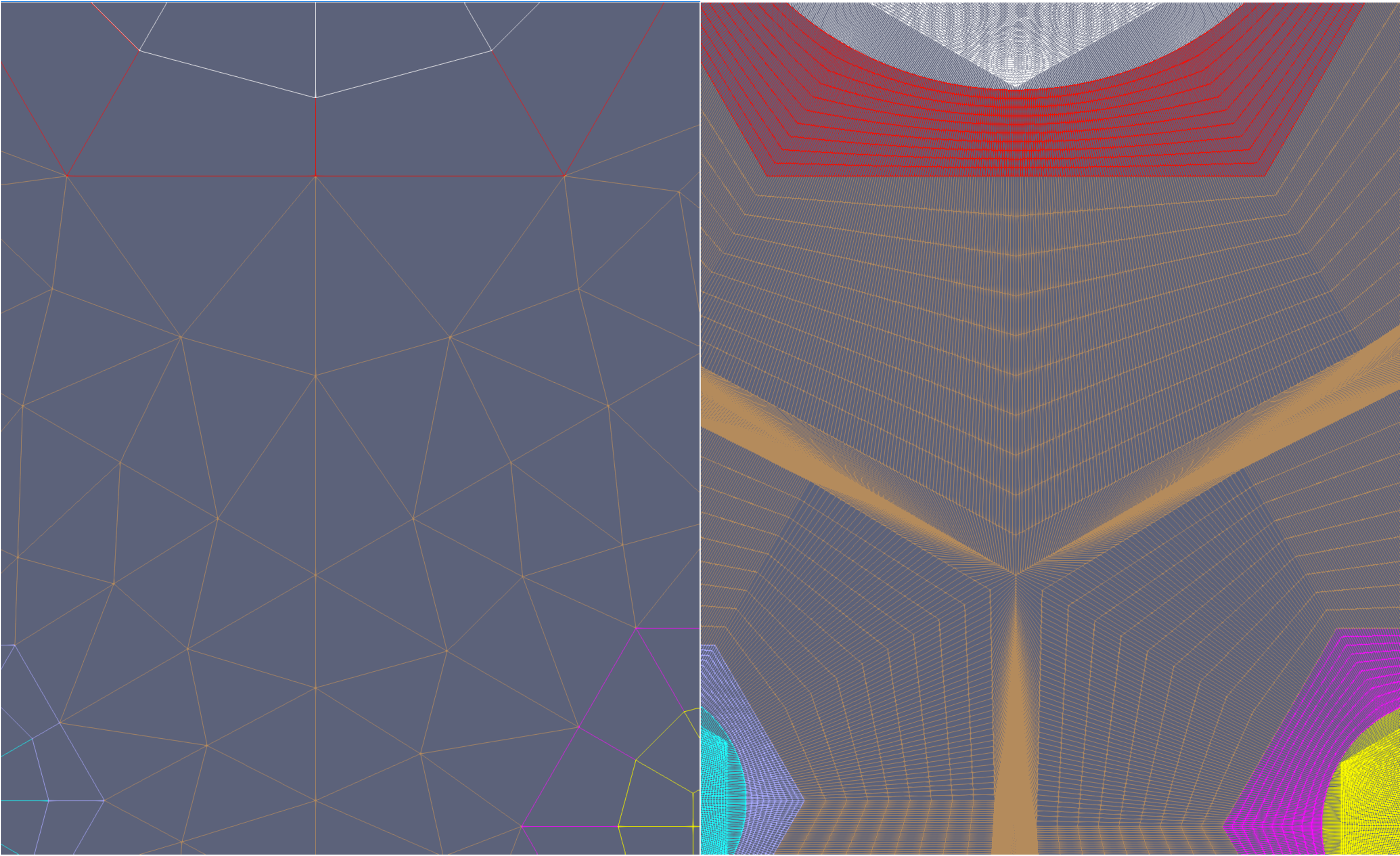
Figure 3: A close-up comparison between the virtual core meshes (see Figure 2) generated with and without using this mesh generator.
Handling Reporting IDs
If the input mesh contains extra element integers (reporting IDs), the PatternedHexPeripheralModifier provides options to retain or reassign these reporting IDs (see Figure 4). By default, all the extra element integers existing on the input mesh are retained. Due to the nature of the transition layer which creates a new set of elements, the original boundaries between different reporting ID values have to be slightly shifted after modification. When PatternedHexPeripheralModifier assigns reporting ID values to a new element in the transition layer, it utilizes the reporting ID values of the original element that is nearest to the new element (based on centroid positions) to retain the setting of the input mesh. Alternatively, users can specify the names of reporting IDs to be reassigned through "extra_id_names_to_modify". The customized reporting ID values can then be set by providing the parameter "new_extra_id_values_to_assign".
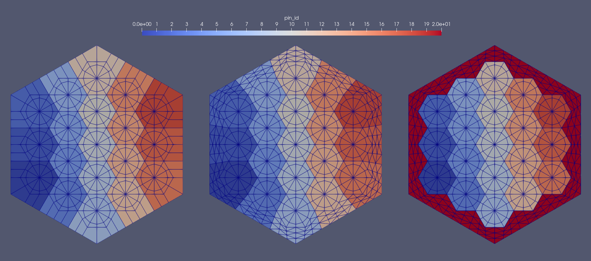
Figure 4: Different approaches to handle a reporting id: (Left) input mesh with reporting id (pin_id); (Middle) retained pin_id for transition layer; (Right) user provided pin_id value for transition layer.
Example Syntax
[pmg_1]
  type = PatternedHexPeripheralModifier
  input = pattern_1
  input_mesh_external_boundary = 10000
  new_num_sector = ${new_num_sector}
  num_layers = ${num_layer}
[]
Input Parameters
- extra_id_names_to_modifyNames of the extra ids that need to be modified along with the peripheral region modification.
C++ Type:std::vector<std::string>
Controllable:No
Description:Names of the extra ids that need to be modified along with the peripheral region modification.
- new_extra_id_values_to_assignOptional extra ids to be assigned to the modified regions to override original values.
C++ Type:std::vector<unsigned long>
Controllable:No
Description:Optional extra ids to be assigned to the modified regions to override original values.
- num_layers1Layers of elements for transition.
Default:1
C++ Type:unsigned int
Controllable:No
Description:Layers of elements for transition.
- show_infoFalseWhether or not to show mesh info after generating the mesh (bounding box, element types, sidesets, nodesets, subdomains, etc)
Default:False
C++ Type:bool
Controllable:No
Description:Whether or not to show mesh info after generating the mesh (bounding box, element types, sidesets, nodesets, subdomains, etc)
- transition_layer_id10000Optional customized block id for the transition layer block.
Default:10000
C++ Type:unsigned short
Controllable:No
Description:Optional customized block id for the transition layer block.
- transition_layer_nametransition_layerOptional customized block name for the transition layer block.
Default:transition_layer
C++ Type:SubdomainName
Controllable:No
Description:Optional customized block name for the transition layer block.
Optional Parameters
- control_tagsAdds user-defined labels for accessing object parameters via control logic.
C++ Type:std::vector<std::string>
Controllable:No
Description:Adds user-defined labels for accessing object parameters via control logic.
- enableTrueSet the enabled status of the MooseObject.
Default:True
C++ Type:bool
Controllable:No
Description:Set the enabled status of the MooseObject.