Introduction
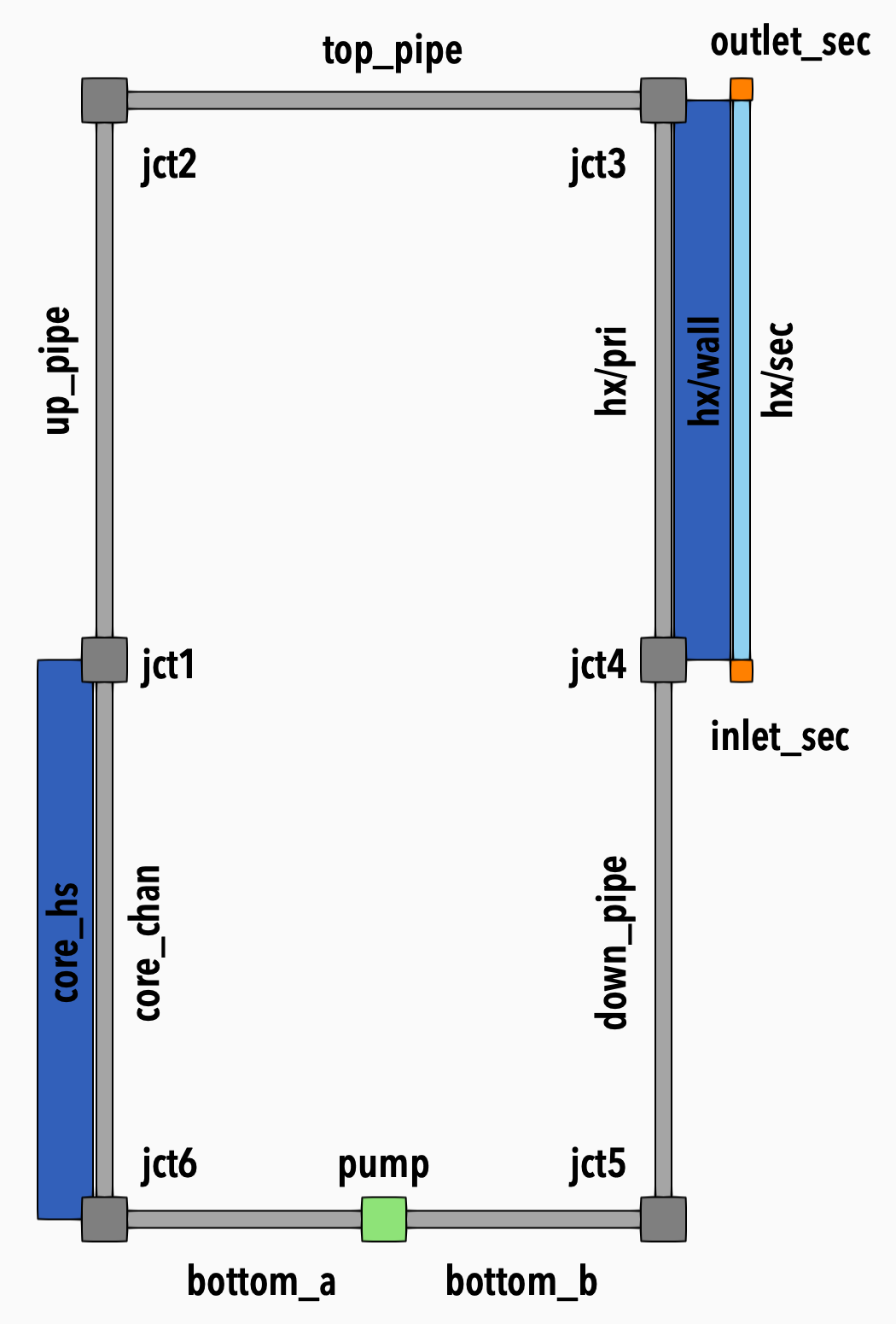
Figure 1: Diagram of the system
In this tutorial, we will build a simple model of system with a primary loop and secondary side. In the primary loop, we will be circulating helium using a pump. We will be adding heat in the core section and removing it in the heat exchanger section. The secondary side will be running liquid water.
We will gradually build the model step by step introducing the following basic concepts:
Fluid property system
Components
Postprocessors
Control logic
Functions
Closure system
Each step will be a complete working model that will be simulating a subset of the final model.
Problem Description
Figure 1 shows the diagram of the modeled system. The tables below list its physical parameters.
Table 1: Primary loop parameters
| Parameter | Value (and unit) |
|---|---|
| Pressure | 10 kPa |
| Temperature | 300 K |
| Mass flow rate | 0.1 g/s |
| Fluid | helium |
Table 2: Core parameters
| Parameter | Value and unit |
|---|---|
| Shape | Heating rod inside a square flow channel |
| Core length | 1 m |
| Side width | 8.7 cm |
| Rod diameter | 2. cm |
Table 3: Heat exchanger parameters
| Parameter | Value and unit |
|---|---|
| Inner diameter | 10 cm |
| Wall thickness | 5 mm |
| Outer diameter | 50 cm |
| Length | 1 m |
Table 4: Secondary loop parameters
| Parameter | Value and unit |
|---|---|
| Mass flow rate | 1 kg/s |
| Fluid | Liquid water |