Example: Heat Pipe-Cooled Micro Reactor (HP-MR)
This section covers the creation of a detailed 1/6 core Heat-Pipe Micro Reactor mesh using the following key steps:
Create fuel/moderator/heat-pipe pin cells
Combine pins into a fuel assembly
Create control drum assembly
Create additional assemblies (reflector, central hole, dummies)
Combine assemblies into a full core
Delete dummy assemblies
Add a core periphery region
Slice full core to 1/6 core
Extrude 2D mesh to 3D
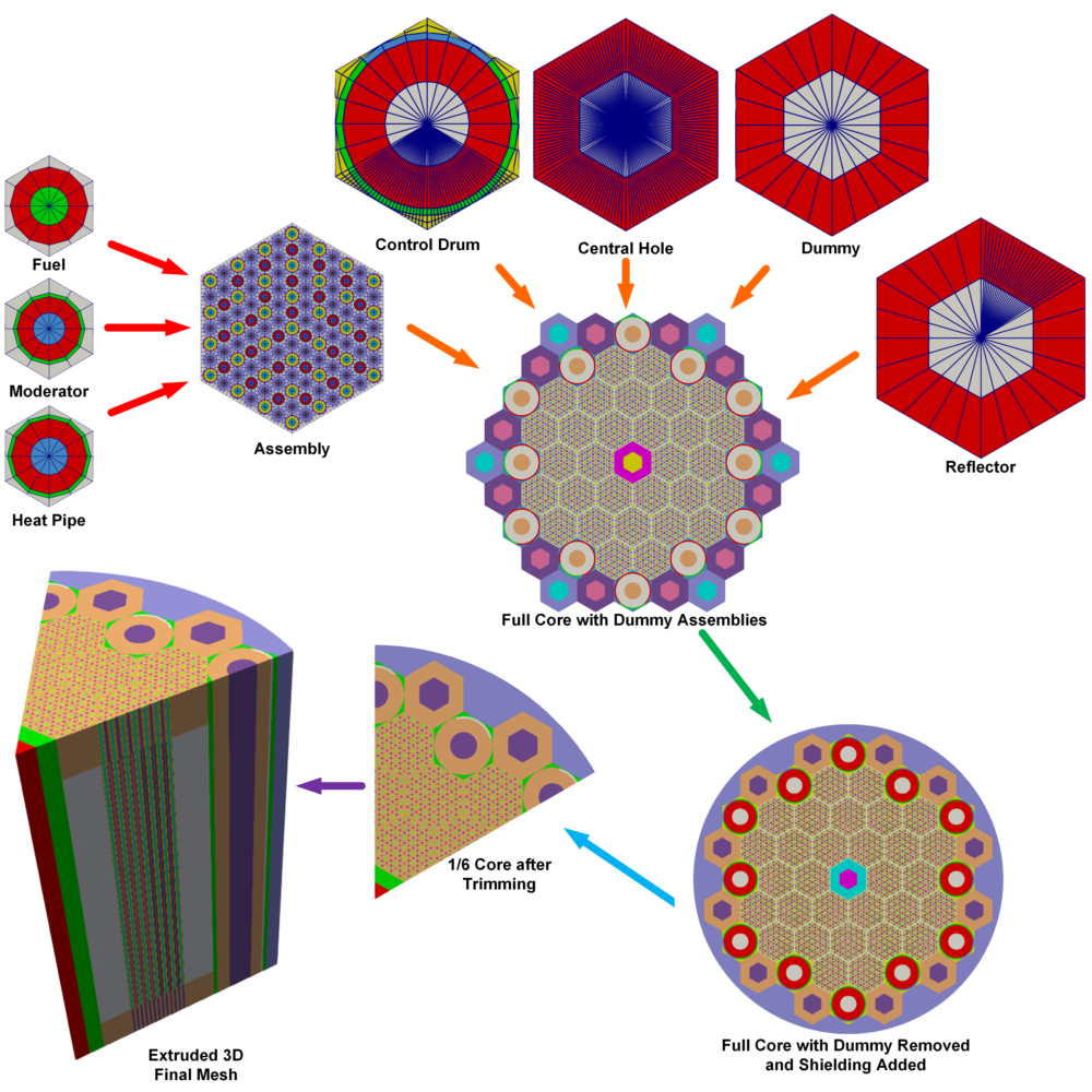
Figure 1: Full workflow of HP-MR example mesh.
Create Pin Unit Cell
The pin cell represents the most basic element in the hierarchical structure of a reactor core. In the case of a heat-pipe micro reactor, typical pin cells include fuel, heat pipe, and moderator. These components are all generated using the PolygonConcentricCircleMeshGenerator. Every pin cell mesh property (e.g., ring radii and intervals) can be tailored to specific needs. The following example shows construction of the moderator pin cell. The heat pipe and fuel pin cells are constructed similarly.
Object
Geometry Features
Center region
0.825 unit radius
2 intervals thick
Outer Ring
0.92 unit radius
1 interval
Hexagonal background
1.15 units apothem
1 interval
Volumes preserved ("preserve_volumes"=
True)TRI center elements ("quad_center_elements"=
False)
Notes
Center of pin unit cell can be meshed by triangular or quadratic elements
Duct regions can also be added to the outer periphery (not used in this example)
Block IDs are assigned for each radial layer
Example
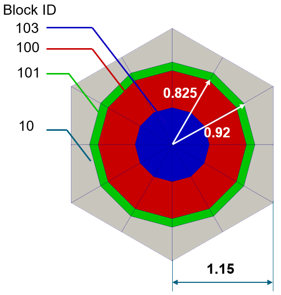
Figure 2: Moderator Pin Cell.
Listing 1: Moderator Pin Cell.
[Mesh<<<{"href": "../../../syntax/Mesh/index.html"}>>>]
  [moderator_pincell]
    type = PolygonConcentricCircleMeshGenerator<<<{"description": "This PolygonConcentricCircleMeshGenerator object is designed to mesh a polygon geometry with optional rings centered inside.", "href": "../../../source/meshgenerators/PolygonConcentricCircleMeshGenerator.html"}>>>
    num_sides<<<{"description": "Number of sides of the polygon."}>>> = 6 # must be six to use hex pattern
    num_sectors_per_side<<<{"description": "Number of azimuthal sectors per polygon side (rotating counterclockwise from top right face)."}>>> = '2 2 2 2 2 2 '
    background_intervals<<<{"description": "Number of radial meshing intervals in background region (area between rings and ducts) excluding the background's boundary layers."}>>> = 1
    background_block_ids<<<{"description": "Optional customized block id for the background block."}>>> = '10'
    polygon_size<<<{"description": "Size of the polygon to be generated (given as either apothem or radius depending on polygon_size_style)."}>>> = 1.15
    polygon_size_style<<<{"description": "Style in which polygon size is given (default: apothem)."}>>> = 'apothem'
    ring_radii<<<{"description": "Radii of major concentric circles (rings)."}>>> = '0.825 0.92'
    ring_intervals<<<{"description": "Number of radial mesh intervals within each major concentric circle excluding their boundary layers."}>>> = '2 1'
    ring_block_ids<<<{"description": "Optional customized block ids for each ring geometry block."}>>> = '103 100 101' # 103 is tri mesh
    preserve_volumes<<<{"description": "Volume of concentric circles can be preserved using this function."}>>> = on
    quad_center_elements<<<{"description": "Whether the center elements are quad or triangular."}>>> = false
  []
[]Create Patterned Hexagonal Fuel Assembly
Generated pin cell meshes (fuel, heat pipe, and moderator) are stitched into a fuel assembly using PatternedHexMeshGenerator.
Object
Geometry Features
Hexagonal grid
13.376 units apothem
Note: requires hexagonal input pins
3 input pin types
fuel_pincell
heatpipe_pincell
moderator_pincell (detailed in pervious section)
Background region out to hexagonal boundary
1 interval
Notes
Pattern references input mesh list in order (0-indexed)
Duct regions can also be added to the outer periphery (not used in this example)
Example
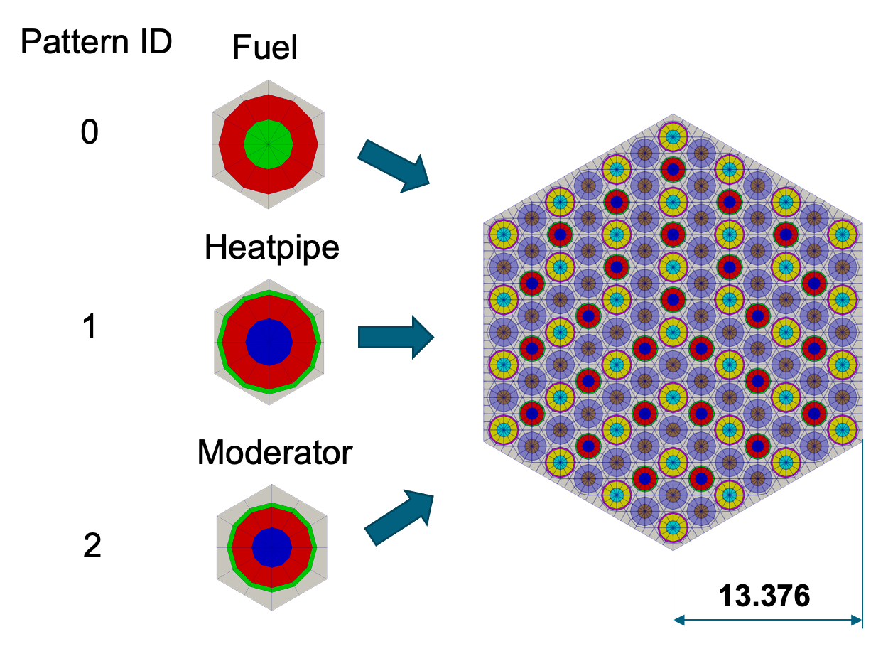
Figure 3: Fuel hex assembly.
Listing 2: Fuel hex assembly.
[Mesh<<<{"href": "../../../syntax/Mesh/index.html"}>>>]
  [fuel_assembly]
    type = PatternedHexMeshGenerator<<<{"description": "This PatternedHexMeshGenerator source code assembles hexagonal meshes into a hexagonal grid and optionally forces the outer boundary to be hexagonal and/or adds a duct.", "href": "../../../source/meshgenerators/PatternedHexMeshGenerator.html"}>>>
    inputs<<<{"description": "The input MeshGenerators."}>>> = 'fuel_pincell heatpipe_pincell moderator_pincell'
    hexagon_size<<<{"description": "Size of the outmost hexagon boundary to be generated; this is required only when pattern type is 'hexagon'."}>>> = 13.376
    background_block_id<<<{"description": "Optional customized block id for the background block in 'assembly' mode; must be provided along with 'duct_block_ids' if 'duct_sizes' is provided."}>>> = 10
    background_intervals<<<{"description": "Radial intervals in the assembly peripheral region."}>>> = 1
    pattern<<<{"description": "A double-indexed hexagonal-shaped array starting with the upper-left corner."}>>> = '1 0 1 0 1 0 1;
              0 2 0 2 0 2 0 0;
             1 0 1 0 1 0 1 2 1;
            0 2 0 2 0 2 0 0 0 0;
           1 0 1 0 1 0 1 2 1 2 1;
          0 2 0 2 0 2 0 0 0 0 0 0;
         1 0 1 0 1 0 1 2 1 2 1 2 1;
          0 2 0 2 0 2 0 0 0 0 0 0;
           1 0 1 0 1 0 1 2 1 2 1;
            0 2 0 2 0 2 0 0 0 0;
             1 0 1 0 1 0 1 2 1;
              0 2 0 2 0 2 0 0;
               1 0 1 0 1 0 1'
  []
[]Fuel-Only Core
The HP-MR utilizes several different assembly types, but as simplified example, consider a core composed only of fuel assemblies.
Object
Geometry Features
61 assembly core
Whole core rotated 60°
Notes
Example
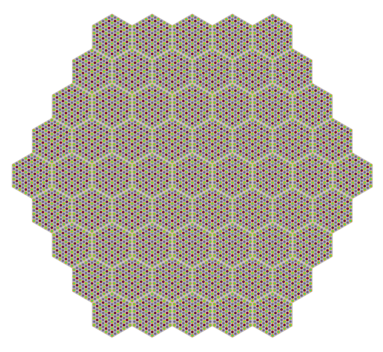
Figure 4: Full fuel core assembly.
Listing 3: Full fuel core assembly.
[Mesh<<<{"href": "../../../syntax/Mesh/index.html"}>>>]
  [fuel_core]
    type = PatternedHexMeshGenerator<<<{"description": "This PatternedHexMeshGenerator source code assembles hexagonal meshes into a hexagonal grid and optionally forces the outer boundary to be hexagonal and/or adds a duct.", "href": "../../../source/meshgenerators/PatternedHexMeshGenerator.html"}>>>
    inputs<<<{"description": "The input MeshGenerators."}>>> = 'fuel_assembly'
    # Pattern ID  0
    pattern_boundary<<<{"description": "The boundary shape of the patterned mesh."}>>> = none
    generate_core_metadata<<<{"description": "A Boolean parameter that controls whether the core related metadata is generated for other MOOSE objects such as 'MultiControlDrumFunction' or not."}>>> = true
    pattern<<<{"description": "A double-indexed hexagonal-shaped array starting with the upper-left corner."}>>> = '0 0 0 0 0;
              0 0 0 0 0 0;
             0 0 0 0 0 0 0;
            0 0 0 0 0 0 0 0;
           0 0 0 0 0 0 0 0 0;
            0 0 0 0 0 0 0 0;
             0 0 0 0 0 0 0;
              0 0 0 0 0 0;
               0 0 0 0 0'
    rotate_angle<<<{"description": "Rotate the entire patterned mesh by a certain degrees that is defined here."}>>> = 60
  []
[]Control Drum Assembly
Control drums are a type of control device used in some small reactor systems to regulate the reactor's power output and maintain a stable operating condition. The generation of control drum mesh involves two steps:
Define control drum mesh with HexagonConcentricCircleAdaptiveBoundaryMeshGenerator
Split outer ring into 2 separate block IDs using AzimuthalBlockSplitGenerator to account for control material zone.
Object
Geometry Features
Center region
12.25 unit radius
2 radial intervals
Absorber Ring
13.25 unit radius
1 radial interval
Outer ring block ID from 45° to 135° is changed to a different ID for this case using AzimuthalBlockSplitGenerator in a second step
Hexagonal background
13.376 unit apothem (half-pitch)
4 azimuthal sectors on each hexagon face, except for the two faces which require more azimuthal sectors to match neighboring fuel assemblies
2 radial intervals
Notes
Circular volumes preserved regardless of meshing fidelity ("preserve_volumes"=
true)Side node adaptation performed for instances with neighboring fuel assemblies. The reference side number (sides_to_adapt) and assembly neighbor meshes (inputs) are taken as input so that the nodes can be placed correctly on the control drum mesh to match the neighbor meshes.
HexagonConcentricCircleAdaptiveBoundaryMeshGenerator is used in this case to create a "single pin" hexagonal assembly with sides matching another mesh. For example, in cases where the node counts on the edges of the control drum and fuel assembly differ, the HexagonConcentricCircleAdaptiveBoundaryMeshGenerator can automatically adjust the mesh density along the control drum's boundary to ensure compatibility.
This meshing method is intended for analyzing a static control drum position. For transient control drum rotation (and control rod insertion), this azimuthal block split is not needed as Griffin uses special material definitions to define the absorber location as a function of time.
Example (Step 1 - Generate Control Drum)
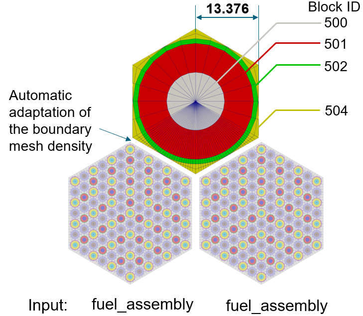
Figure 5: Control Drum Generation.
Listing 4: Control Drum Generation.
[Mesh<<<{"href": "../../../syntax/Mesh/index.html"}>>>]
  [cd1_step1]
    type = HexagonConcentricCircleAdaptiveBoundaryMeshGenerator<<<{"description": "This HexagonConcentricCircleAdaptiveBoundaryMeshGenerator object is designed to generate hexagonal meshes with adaptive boundary to facilitate stitching.", "href": "../../../source/meshgenerators/HexagonConcentricCircleAdaptiveBoundaryMeshGenerator.html"}>>>
    meshes_to_adapt_to<<<{"description": "The name list of the input meshes to adapt to."}>>> = 'fuel_assembly fuel_assembly'
    sides_to_adapt<<<{"description": "List of the hexagon reference side indices that correspond to the sides that need adaptive meshing. The meshes to adapt these sides to are provided in 'inputs'."}>>> = '3 4'
    num_sectors_per_side<<<{"description": "Number of azimuthal sectors per polygon side (rotating counterclockwise from top right face)."}>>> = '4 4 4 4 4 4'
    hexagon_size<<<{"description": "Size of the hexagon to be generated."}>>> = 13.376
    background_intervals<<<{"description": "Number of radial meshing intervals in background region (area between rings and ducts) excluding the background's boundary layers."}>>> = 2
    background_block_ids<<<{"description": "Optional customized block id for the background block."}>>> = 504
    ring_radii<<<{"description": "Radii of major concentric circles (rings)."}>>> = '12.25 13.25'
    ring_intervals<<<{"description": "Number of radial mesh intervals within each major concentric circle excluding their boundary layers."}>>> = '2 1'
    ring_block_ids<<<{"description": "Optional customized block ids for each ring geometry block."}>>> = '500 501 502'
    preserve_volumes<<<{"description": "Volume of concentric circles can be preserved using this function."}>>> = true
    is_control_drum<<<{"description": "Whether this mesh is for a control drum. The value can be set as 'false' if the user wants to use this object for other components."}>>> = true
  []
[]Example (Step 2 - Block Splitting to Define Absorber Segment)
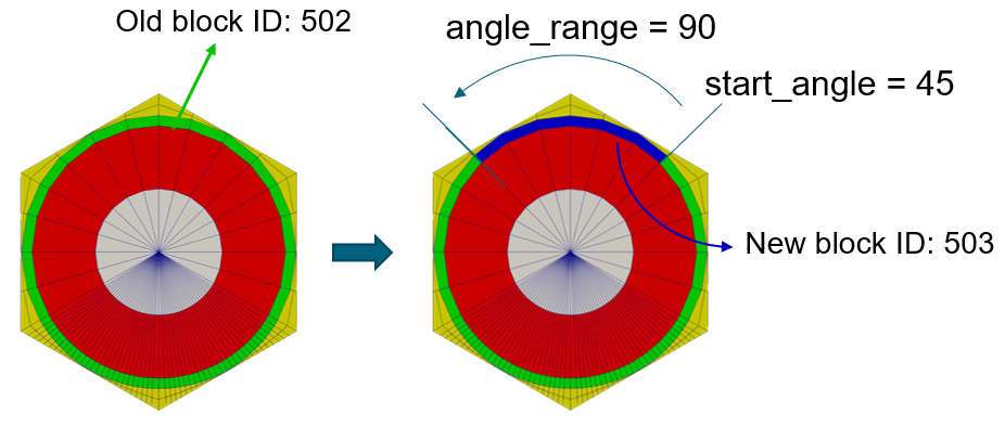
Figure 6: Block ID swaps.
Listing 5: Block ID swaps.
[Mesh<<<{"href": "../../../syntax/Mesh/index.html"}>>>]
  [cd1]
    type = AzimuthalBlockSplitGenerator<<<{"description": "This AzimuthalBlockSplitGenerator object takes in a polygon/hexagon concentric circle mesh and renames blocks on a user-defined azimuthal segment / wedge of the mesh.", "href": "../../../source/meshgenerators/AzimuthalBlockSplitGenerator.html"}>>>
    input<<<{"description": "The input mesh to be modified."}>>> = cd1_step1
    start_angle<<<{"description": "Starting azimuthal angle of the new block."}>>> = 45
    angle_range<<<{"description": "Azimuthal angle range of the new block."}>>> = 90
    old_blocks<<<{"description": "The list of blocks in the input mesh that need to be modified."}>>> = 502
    new_block_ids<<<{"description": "The block IDs to be used for the new selected azimuthal angle blocks."}>>> = 503
  []
[]Create Additional Assemblies (Reflector, Air, Dummy)
Other components of the reactor, such as reflectors and air holes, can also be created using the HexagonConcentricCircleAdaptiveBoundaryMeshGenerator. Additionally, to achieve the necessary hexagonal shape for the PatternedHexMeshGenerator, dummy blocks are required. These dummy blocks will be eliminated once the reactor core is constructed.
Object
Geometry Features
13.376 unit apothem
4 azimuthal sectors on each hexagon side, except where more required for conformal meshing with neighbors (two sides of reflector, all sides of air hole)
2 radial intervals
No concentric circles included (no pins)
Side node adaptation for case with neighboring fuel assemblies
Reflector assemblies along the core outer boundary (multiple reflector geometries needed based on location in the core)
Single central air hole assembly
Multiple "Dummy" assemblies needed for patterning (to be deleted later), all with identical boundary densities (only one geometry needed, with same block ID for easy deletion later).
Notes
The boundary nodes on two neighboring assemblies need to match up in order for the assemblies to be stitched together. Assemblies that neighbor several different assembly types (control drums, reflectors) are generally created last so that the boundaries can be specified based on the meshes these need to match.
Example
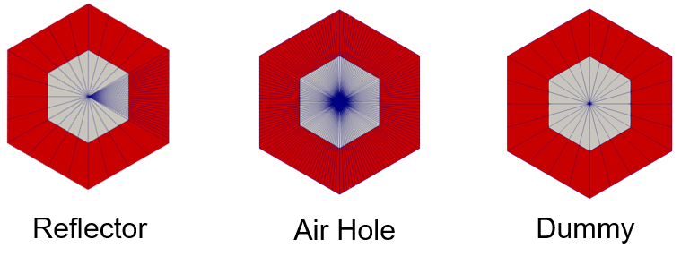
Figure 7: Additional assembly types.
Listing 6: Reflector assembly example.
[Mesh<<<{"href": "../../../syntax/Mesh/index.html"}>>>]
  [refl1]
    type = HexagonConcentricCircleAdaptiveBoundaryMeshGenerator<<<{"description": "This HexagonConcentricCircleAdaptiveBoundaryMeshGenerator object is designed to generate hexagonal meshes with adaptive boundary to facilitate stitching.", "href": "../../../source/meshgenerators/HexagonConcentricCircleAdaptiveBoundaryMeshGenerator.html"}>>>
    meshes_to_adapt_to<<<{"description": "The name list of the input meshes to adapt to."}>>> = 'fuel_assembly'
    sides_to_adapt<<<{"description": "List of the hexagon reference side indices that correspond to the sides that need adaptive meshing. The meshes to adapt these sides to are provided in 'inputs'."}>>> = '4'
    num_sectors_per_side<<<{"description": "Number of azimuthal sectors per polygon side (rotating counterclockwise from top right face)."}>>> = '4 4 4 4 4 4'
    hexagon_size<<<{"description": "Size of the hexagon to be generated."}>>> = 13.376
    background_intervals<<<{"description": "Number of radial meshing intervals in background region (area between rings and ducts) excluding the background's boundary layers."}>>> = 2
    background_block_ids<<<{"description": "Optional customized block id for the background block."}>>> = '400 401'
  []
[]Listing 7: Air center assembly example.
[Mesh<<<{"href": "../../../syntax/Mesh/index.html"}>>>]
  [air_center]
    type = HexagonConcentricCircleAdaptiveBoundaryMeshGenerator<<<{"description": "This HexagonConcentricCircleAdaptiveBoundaryMeshGenerator object is designed to generate hexagonal meshes with adaptive boundary to facilitate stitching.", "href": "../../../source/meshgenerators/HexagonConcentricCircleAdaptiveBoundaryMeshGenerator.html"}>>>
    num_sectors_per_side<<<{"description": "Number of azimuthal sectors per polygon side (rotating counterclockwise from top right face)."}>>> = '4 4 4 4 4 4'
    meshes_to_adapt_to<<<{"description": "The name list of the input meshes to adapt to."}>>> = 'fuel_assembly fuel_assembly fuel_assembly fuel_assembly fuel_assembly fuel_assembly'
    sides_to_adapt<<<{"description": "List of the hexagon reference side indices that correspond to the sides that need adaptive meshing. The meshes to adapt these sides to are provided in 'inputs'."}>>> = '0 1 2 3 4 5'
    hexagon_size<<<{"description": "Size of the hexagon to be generated."}>>> = 13.376
    background_intervals<<<{"description": "Number of radial meshing intervals in background region (area between rings and ducts) excluding the background's boundary layers."}>>> = 2
    background_block_ids<<<{"description": "Optional customized block id for the background block."}>>> = '600 601'
  []
[]Listing 8: Dummy assembly example.
[Mesh<<<{"href": "../../../syntax/Mesh/index.html"}>>>]
  [dummy]
    type = HexagonConcentricCircleAdaptiveBoundaryMeshGenerator<<<{"description": "This HexagonConcentricCircleAdaptiveBoundaryMeshGenerator object is designed to generate hexagonal meshes with adaptive boundary to facilitate stitching.", "href": "../../../source/meshgenerators/HexagonConcentricCircleAdaptiveBoundaryMeshGenerator.html"}>>>
    num_sectors_per_side<<<{"description": "Number of azimuthal sectors per polygon side (rotating counterclockwise from top right face)."}>>> = '4 4 4 4 4 4'
    hexagon_size<<<{"description": "Size of the hexagon to be generated."}>>> = 13.376
    background_intervals<<<{"description": "Number of radial meshing intervals in background region (area between rings and ducts) excluding the background's boundary layers."}>>> = 2
    background_block_ids<<<{"description": "Optional customized block id for the background block."}>>> = '700 701'
    # external_boundary_id = 9998
  []
[]Create Patterned Full Core
Generated reactor component meshes (fuel assembly, control drum, reflector, air hole and dummy) are stitched into a 2D hexagonal lattice (reactor core) using PatternedHexMeshGenerator.
Object
Geometry Features
Outer hex boundary disabled ("pattern_boundary"=
none)Whole core rotated 60°
5 Input geometry types
Fuel assembly
Control drum (12 meshes created for different boundary arrangements)
Reflector (6 meshes created for different boundary arrangements)
Air hole center
Dummy assemblies
Notes
PatternedHexMeshGenerator requires a "perfect" hex pattern. "Empty" spots should be defined with dummy assemblies and later deleted.
Example
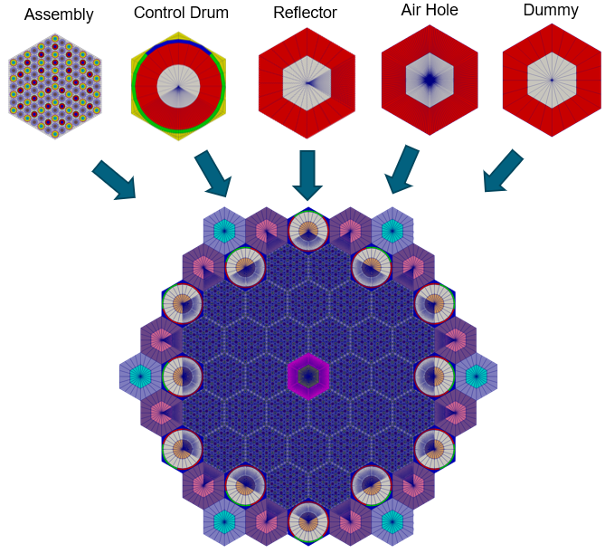
Figure 8: Full core assembly.
Listing 9: Full core assembly.
[Mesh<<<{"href": "../../../syntax/Mesh/index.html"}>>>]
  [core]
    type = PatternedHexMeshGenerator<<<{"description": "This PatternedHexMeshGenerator source code assembles hexagonal meshes into a hexagonal grid and optionally forces the outer boundary to be hexagonal and/or adds a duct.", "href": "../../../source/meshgenerators/PatternedHexMeshGenerator.html"}>>>
    inputs<<<{"description": "The input MeshGenerators."}>>> = 'fuel_assembly cd1 cd2 cd3 cd4 cd5 cd6 cd7 cd8 cd9 cd10 cd11 cd12 refl1 refl2 refl3 refl4 refl5 refl6 dummy air_center'
    # Pattern ID  0           1   2   3   4   5   6   7   8   9   10   11   12    13    14    15    16    17    18   19  20
    pattern_boundary<<<{"description": "The boundary shape of the patterned mesh."}>>> = none
    generate_core_metadata<<<{"description": "A Boolean parameter that controls whether the core related metadata is generated for other MOOSE objects such as 'MultiControlDrumFunction' or not."}>>> = true
    pattern<<<{"description": "A double-indexed hexagonal-shaped array starting with the upper-left corner."}>>> = '19 13 1  18 19;
             13 12  0  0  2 18;
           11  0  0  0  0  0  3;
          14 0  0   0  0  0  0 17;
        19 10  0  0  20  0  0  4 19;
          14 0  0   0  0  0  0 17;
            9  0  0  0  0  0  5;
             15  8  0  0  6 16;
               19 15  7 16 19'
    rotate_angle<<<{"description": "Rotate the entire patterned mesh by a certain degrees that is defined here."}>>> = 60
  []
[]Delete Dummy Assemblies
Dummy blocks were used in the previous step to facilitate the core pattern but are not part of the final mesh. We now delete them.
Object
Geometry Features
Remove "dummy" assemblies which were added only for core hex patterning
Notes
The blocks IDs of the dummy assembly were defined by the user in the definition of the dummy assembly
Set the new outer boundaries that result from the deleted assemblies to have the same sideset ID as the existing outer boundary (this step is crucial to ensure the entire outer boundary can be referenced in Griffin for sideset assignment)
Example
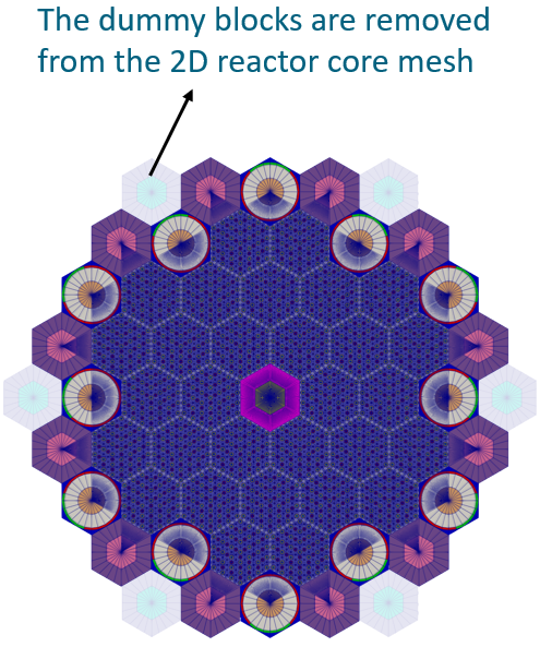
Figure 9: Full core assembly without dummies.
Listing 10: Full core assembly without dummies.
[Mesh<<<{"href": "../../../syntax/Mesh/index.html"}>>>]
  [del_dummy]
    type = BlockDeletionGenerator<<<{"description": "Mesh generator which removes elements from the specified subdomains", "href": "../../../source/meshgenerators/BlockDeletionGenerator.html"}>>>
    block<<<{"description": "The list of blocks to be processed (deleted or kept)"}>>> = '700 701'
    input<<<{"description": "The mesh we want to modify"}>>> = core
    new_boundary<<<{"description": "optional boundary name to assign to the cut surface"}>>> = 10000
  []
[]Add Core Periphery
A peripheral ring (shield) can be incorporated into the 2D reactor core using either the PeripheralRingMeshGenerator or the PeripheralTriangleMeshGenerator. The former generates a quad mesh, while the latter generates a tri mesh. These two mesh generators also allow the user to control mesh density. Using the quadrilateral mesh option permits easier symmetry trimming options down the line.
Object
Geometry Features
115.0 units vessel radius
1 radial interval
Notes
Use existing core outer boundary ID as input boundary which describes which boundary the peripheral ring should start from
Example
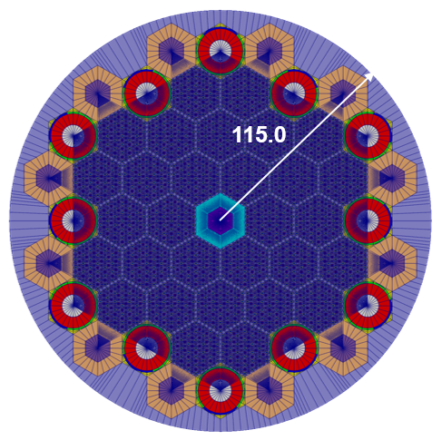
Figure 10: Core periphery.
Listing 11: Core periphery.
[Mesh<<<{"href": "../../../syntax/Mesh/index.html"}>>>]
  [outer_shield]
    type = PeripheralRingMeshGenerator<<<{"description": "This PeripheralRingMeshGenerator object adds a circular peripheral region to the input mesh.", "href": "../../../source/meshgenerators/PeripheralRingMeshGenerator.html"}>>>
    input<<<{"description": "The input mesh to be modified."}>>> = del_dummy
    peripheral_layer_num<<<{"description": "The radial layers of the peripheral ring to be added."}>>> = 1
    peripheral_ring_radius<<<{"description": "Radius of the peripheral ring to be added."}>>> = 115.0
    input_mesh_external_boundary<<<{"description": "The external boundary of the input mesh."}>>> = 10000
    peripheral_ring_block_id<<<{"description": "The block id assigned to the created peripheral layer."}>>> = 250
    peripheral_ring_block_name<<<{"description": "The block name assigned to the created peripheral layer."}>>> = outer_shield
  []
[]Slice to 1/6 Core
To conserve computational resources, users may create a half core or 1/6 symmetric reactor core. The PlaneDeletionGenerator can be employed to trim the 2D full core mesh into the desired symmetrical configuration in this case because the desired cuts lie along existing element boundaries. Alternatively, HexagonMeshTrimmer could be used to perform this trimming.
Object
Geometry Features
Trimming plane defined by a point and a normal vector
Elements whose centroids lie "above" (in the direction of the normal vector) the plane will be deleted
Set new outer boundary ID on sliced lines to be referenced later
To slice the full core in half
Point = , normal = (60° from +)
To slice the half core into 1/3
Point = , normal = (-60° from +)
Notes
Advanced trimming options are available (see HexagonMeshTrimmer). Trimming should only be performed along lines of symmetry.
Example
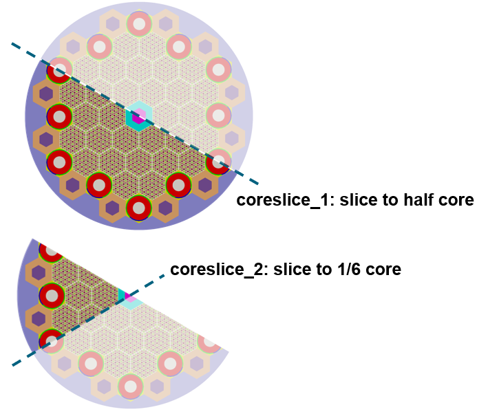
Figure 11: 1/6 core slice in two steps.
Listing 12: Slice full core in 1/2 example.
[Mesh<<<{"href": "../../../syntax/Mesh/index.html"}>>>]
  [coreslice_1]
    type = PlaneDeletionGenerator<<<{"description": "Removes elements lying 'above' the plane (in the direction of the normal).", "href": "../../../source/meshgenerators/PlaneDeletionGenerator.html"}>>>
    point<<<{"description": "The point that defines the plane"}>>> = '0 0 0'
    normal<<<{"description": "The normal that defines the plane"}>>> = '10 17.32 0'
    input<<<{"description": "The mesh we want to modify"}>>> = outer_shield
    new_boundary<<<{"description": "optional boundary name to assign to the cut surface"}>>> = 147
  []
[]Listing 13: Slice 1/2 core in 1/3 example.
[Mesh<<<{"href": "../../../syntax/Mesh/index.html"}>>>]
  [coreslice_2]
    type = PlaneDeletionGenerator<<<{"description": "Removes elements lying 'above' the plane (in the direction of the normal).", "href": "../../../source/meshgenerators/PlaneDeletionGenerator.html"}>>>
    point<<<{"description": "The point that defines the plane"}>>> = '0 0 0'
    normal<<<{"description": "The normal that defines the plane"}>>> = '10 -17.32 0'
    input<<<{"description": "The mesh we want to modify"}>>> = coreslice_1
    new_boundary<<<{"description": "optional boundary name to assign to the cut surface"}>>> = 147
  []
[]Extrude to 3D
The AdvancedExtruderGenerator performs 2D to 3D extrusion, and allows users to control elevations through variable extrusion (axial) lengths. This mesh generator also has features like assigning new subdomain IDs at different axial layers.
Object
Geometry Features
Extrude the 2D mesh in + direction
Split into 3 axial intervals
Heights for each interval: 20 units, 160 units, 20 units
Number of layers in each interval: 1, 8, 1
Set top/bottom boundary IDs to be referenced later
Notes
Here we explain the concept of subdomain swaps. By default, when 2D elements are extruded to 3D using AdvancedExtruderGenerator, they retain the same subdomain IDs as their original 2D elements. In the 3D HPMR, distinct subdomain IDs are required for the upper and lower reflector regions, as well as for the core center region. This can be achieved using the subdomain swap function in the AdvancedExtruderGenerator through the "subdomain_swaps" parameter. Each element of the "subdomain_swaps" vector contains subdomain remapping information for a specific elevation, with the first element representing the initial extruded elevation. For instance, a 2D moderator mesh with block ID 100 can be extruded to 3D using the following "subdomain_swaps": '100 1000; 100 100; 100 1000', where 1000 is the block ID of the reflector. The generated mesh will be defined to be three layers with the upper and bottom meshes of block ID 1000 and the center region maintain the block ID of 100. The resulting mesh will have three layers, with the top and bottom layers having a block ID of 1000 (reflector), while the central region retains the block ID of 100 (moderator).
Example
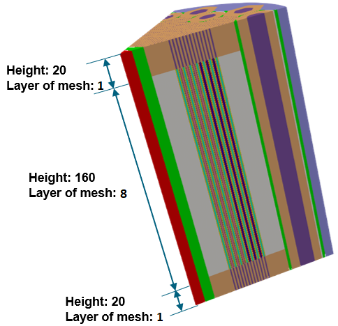
Figure 12: 1/6 2D core extruded to 3D.
Listing 14: 1/6 2D core extruded to 3D.
[Mesh<<<{"href": "../../../syntax/Mesh/index.html"}>>>]
  [extrude]
    type = AdvancedExtruderGenerator<<<{"description": "Extrudes a 1D mesh into 2D, or a 2D mesh into 3D, and supports a variable height for each elevation, variable number of layers within each elevation, variable growth factors of axial element sizes within each elevation and remap subdomain_ids, boundary_ids and element extra integers within each elevation as well as interface boundaries between neighboring elevation layers, as well as following a 1D curve and modifying the radial (normal to the extrusion axis) extent of the geometry.", "href": "../../../source/meshgenerators/AdvancedExtruderGenerator.html"}>>>
    input<<<{"description": "The mesh to extrude"}>>> = coreslice_2
    heights<<<{"description": "The height of each elevation"}>>> = '20 160 20'
    num_layers<<<{"description": "The number of layers for each elevation - must be num_elevations in length!"}>>> = '1 8 1'
    direction<<<{"description": "A vector that points in the direction to extrude (note, this will be normalized internally - so don't worry about it here)"}>>> = '0 0 1'
    subdomain_swaps<<<{"description": "For each row, every two entries are interpreted as a pair of 'from' and 'to' to remap the subdomains for that elevation"}>>> = '10 1000 100 1000 101 1000 103 1003 200 1000 201 1000 203 1003 301 1000 303 1003;
                        10 10   100 100  101 101  103 103  200 200  201 201  203 203  301 301  303 303;
                        10 1000 100 1000 101 1000 103 1003 200 200  201 201  203 203  301 1000 303 1003'
    top_boundary<<<{"description": "The boundary name to set on the top boundary. If omitted an ID will be generated."}>>> = 2000
    bottom_boundary<<<{"description": "The boundary name to set on the bottom boundary. If omitted an ID will be generated."}>>> = 3000
  []
[]Using the Mesh in Downstream Physics Applications (Griffin)
We briefly describe some key steps which are required to use the resulting mesh in Griffin. Namely, block IDs (subdomain_id) are referenced in Griffin to assign materials to elements. The external boundary sideset IDs are referenced in Griffin to assign boundary conditions.
Assignment of Material Properties to Blocks
All blocks in the mesh must be assigned to a material in Griffin. The blocks are depicted in Figure 13 (left) using different colors for each block. Figure 13 (right) highlights two specific blocks and their associated material IDs as an example of block IDs that must be referenced in Griffin.
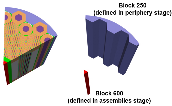
Figure 13: Locations of blocks which are assigned to materials in the Griffin input file.
Listing 15: Material property assignment example.
[Materials<<<{"href": "../../../syntax/Materials/index.html"}>>>]
  [mat1]
    type = CoupledFeedbackNeutronicsMaterial
    block = '250'
    material_id = 1
  []
  [mat2]
    type = CoupledFeedbackNeutronicsMaterial
    block = '600'
    material_id = 2
  []
  # Repeat for all other blocks in mesh
[]Assignment of Boundary Conditions to Sidesets
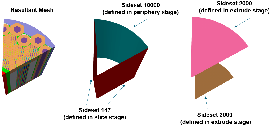
Figure 14: The key sidesets which are assigned boundary conditions in the Griffin input file.
Generation of Coarse Mesh in Griffin
We briefly touch on mesh generation for the Coarse Mesh Finite Difference acceleration option in Griffin. There are three options:
Option 1: Define "coarse" mesh that is identical to fine mesh
Option 2: Define coarse mesh covering the same geometry as the fine mesh but with a coarser mesh refinement
Option 3: Define a regular square grid covering the entire mesh domain (and beyond)
Examples of options 2 and 3 are provided in the following images.
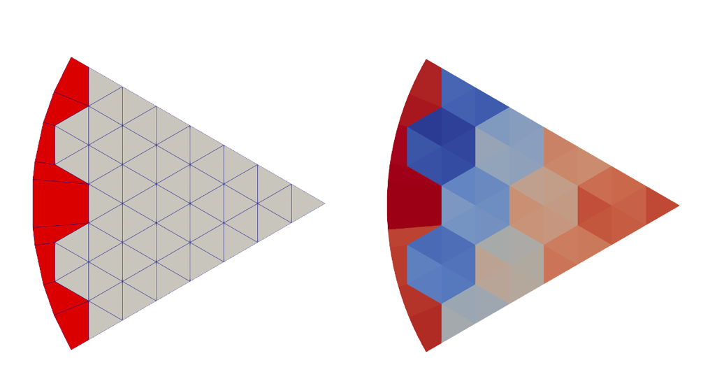
Figure 15: Separately generated fine-mesh stencil used for coarse mesh generation of HPMR mesh (left), and HPMR mesh colored by coarse_element_id.
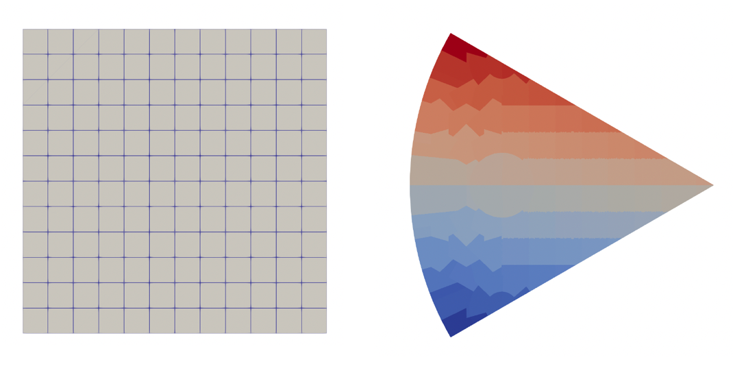
Figure 16: Cartesian stencil used for coarse mesh generation of HPMR mesh (left), and HPMR mesh colored by coarse_element_id.
preserve_volumes
Default:True
C++ Type:bool
Controllable:No
Description:Volume of concentric circles can be preserved using this function.
quad_center_elements
Default:False
C++ Type:bool
Controllable:No
Description:Whether the center elements are quad or triangular.
(tutorials/tutorial04_meshing/app/test/tests/reactor_examples/hpmr/hpmr.i)
# Heat Pipe-Cooled Micro Reactor - 3D Core with Heterogeneous Assemblies

[Mesh]

  #################################      # This parameter allows us to execute the file but stop at this block so we can see intermediate output.
  final_generator = moderator_pincell    # User: Change this based on build step
  ################################

  # step 1: moderator_pincell
  # step 2: fuel_assembly
  # optional: fuel_core
  # step 3: cd1
  # step 4: refl1
  # step 5: core
  # step 6: del_dummy
  # step 7: outer_shield
  # step 8: coreslice_2
  # step 9: extrude


  ### Step 1. Create Pin Unit Cells
  # There are 3 unique pin in the fuel assembly

  [moderator_pincell]
    type = PolygonConcentricCircleMeshGenerator
    num_sides = 6 # must be six to use hex pattern
    num_sectors_per_side = '2 2 2 2 2 2 '
    background_intervals = 1
    background_block_ids = '10'
    polygon_size = 1.15
    polygon_size_style ='apothem'
    ring_radii = '0.825 0.92'
    ring_intervals = '2 1'
    ring_block_ids = '103 100 101' # 103 is tri mesh
    preserve_volumes = on
    quad_center_elements = false
  []
  [heatpipe_pincell]
    type = PolygonConcentricCircleMeshGenerator
    num_sides = 6 # must be six to use hex pattern
    num_sectors_per_side = '2 2 2 2 2 2 '
    background_intervals = 1
    background_block_ids = '10'
    polygon_size = 1.15
    polygon_size_style ='apothem'
    ring_radii = '0.97 1.07'
    ring_intervals = '2 1'
    ring_block_ids = '203 200 201' # 203 is tri mesh
    preserve_volumes = on
    quad_center_elements = false
  []
  [fuel_pincell]
    type = PolygonConcentricCircleMeshGenerator
    num_sides = 6 # must be six to use hex pattern
    num_sectors_per_side = '2 2 2 2 2 2 '
    background_intervals = 1
    background_block_ids = '10'
    polygon_size = 1.15
    polygon_size_style ='apothem'
    ring_radii = '1'
    ring_intervals = '2'
    ring_block_ids = '303 301'  # 303 is tri mesh
    preserve_volumes = on
    quad_center_elements = false
  []

  ### Step 2. Create Patterned Hexagonal Fuel Assembly

  [fuel_assembly]
    type = PatternedHexMeshGenerator
    inputs = 'fuel_pincell heatpipe_pincell moderator_pincell'
    hexagon_size = 13.376
    background_block_id = 10
    background_intervals = 1
    pattern = '1 0 1 0 1 0 1;
              0 2 0 2 0 2 0 0;
             1 0 1 0 1 0 1 2 1;
            0 2 0 2 0 2 0 0 0 0;
           1 0 1 0 1 0 1 2 1 2 1;
          0 2 0 2 0 2 0 0 0 0 0 0;
         1 0 1 0 1 0 1 2 1 2 1 2 1;
          0 2 0 2 0 2 0 0 0 0 0 0;
           1 0 1 0 1 0 1 2 1 2 1;
            0 2 0 2 0 2 0 0 0 0;
             1 0 1 0 1 0 1 2 1;
              0 2 0 2 0 2 0 0;
               1 0 1 0 1 0 1'
  []

  ### Optional. Create Fuel-Only Core
  # optional example, create a core made only of fuel assemblies

  [fuel_core]
    type = PatternedHexMeshGenerator
    inputs = 'fuel_assembly'
    # Pattern ID  0
    pattern_boundary = none
    generate_core_metadata = true
    pattern = '0 0 0 0 0;
              0 0 0 0 0 0;
             0 0 0 0 0 0 0;
            0 0 0 0 0 0 0 0;
           0 0 0 0 0 0 0 0 0;
            0 0 0 0 0 0 0 0;
             0 0 0 0 0 0 0;
              0 0 0 0 0 0;
               0 0 0 0 0'
    rotate_angle = 60
  []

  ### Step 3. Create Control Drum Assembly
  # 12 control drum (cd1-cd12) meshes are needed for different locations and node boundary conditions

  [cd1_step1]
    type =HexagonConcentricCircleAdaptiveBoundaryMeshGenerator
    meshes_to_adapt_to = 'fuel_assembly fuel_assembly'
    sides_to_adapt = '3 4'
    num_sectors_per_side= '4 4 4 4 4 4'
    hexagon_size = 13.376
    background_intervals = 2
    background_block_ids = 504
    ring_radii = '12.25 13.25'
    ring_intervals = '2 1'
    ring_block_ids = '500 501 502'
    preserve_volumes = true
    is_control_drum = true
  []
  [cd1]
    type = AzimuthalBlockSplitGenerator
    input = cd1_step1
    start_angle = 45
    angle_range = 90
    old_blocks = 502
    new_block_ids = 503
  []

  [cd2_step1]
    type =HexagonConcentricCircleAdaptiveBoundaryMeshGenerator
    meshes_to_adapt_to = 'fuel_assembly fuel_assembly fuel_assembly'
    sides_to_adapt = '2 3 4'
    num_sectors_per_side= '4 4 4 4 4 4'
    hexagon_size = 13.376
    background_intervals = 2
    background_block_ids = 504
    ring_radii = '12.25 13.25'
    ring_intervals = '2 1'
    ring_block_ids = '500 501 502'
    preserve_volumes = true
    is_control_drum = true
  []
  [cd2]
    type = AzimuthalBlockSplitGenerator
    input = cd2_step1
    start_angle = 15
    angle_range = 90
    old_blocks = 502
    new_block_ids = 503
  []

  [cd3_step1]
    type =HexagonConcentricCircleAdaptiveBoundaryMeshGenerator
    meshes_to_adapt_to = 'fuel_assembly fuel_assembly'
    sides_to_adapt = '2 3'
    num_sectors_per_side= '4 4 4 4 4 4'
    hexagon_size = 13.376
    background_intervals = 2
    background_block_ids = 504
    ring_radii = '12.25 13.25'
    ring_intervals = '2 1'
    ring_block_ids = '500 501 502'
    preserve_volumes = true
    is_control_drum = true
  []
  [cd3]
    type = AzimuthalBlockSplitGenerator
    input = cd3_step1
    start_angle = 345
    angle_range = 90
    old_blocks = 502
    new_block_ids = 503
  []

 [cd4_step1]
    type =HexagonConcentricCircleAdaptiveBoundaryMeshGenerator
    meshes_to_adapt_to = 'fuel_assembly fuel_assembly fuel_assembly'
    sides_to_adapt = '1 2 3'
    num_sectors_per_side= '4 4 4 4 4 4'
    hexagon_size = 13.376
    background_intervals = 2
    background_block_ids = 504
    ring_radii = '12.25 13.25'
    ring_intervals = '2 1'
    ring_block_ids = '500 501 502'
    preserve_volumes = true
    is_control_drum = true
  []
  [cd4]
    type = AzimuthalBlockSplitGenerator
    input = cd4_step1
    start_angle = 315
    angle_range = 90
    old_blocks = 502
    new_block_ids = 503
  []

  [cd5_step1]
    type =HexagonConcentricCircleAdaptiveBoundaryMeshGenerator
    meshes_to_adapt_to = 'fuel_assembly fuel_assembly'
    sides_to_adapt = '1 2'
    num_sectors_per_side= '4 4 4 4 4 4'
    hexagon_size = 13.376
    background_intervals = 2
    background_block_ids = 504
    ring_radii = '12.25 13.25'
    ring_intervals = '2 1'
    ring_block_ids = '500 501 502'
    preserve_volumes = true
    is_control_drum = true
  []
  [cd5]
    type = AzimuthalBlockSplitGenerator
    input = cd5_step1
    start_angle = 285
    angle_range = 90
    old_blocks = 502
    new_block_ids = 503
  []

  [cd6_step1]
    type =HexagonConcentricCircleAdaptiveBoundaryMeshGenerator
    meshes_to_adapt_to = ' fuel_assembly fuel_assembly fuel_assembly'
    sides_to_adapt = '0 1 2'
    num_sectors_per_side= '4 4 4 4 4 4'
    hexagon_size = 13.376
    background_intervals = 2
    background_block_ids = 504
    ring_radii = '12.25 13.25'
    ring_intervals = '2 1'
    ring_block_ids = '500 501 502'
    preserve_volumes = true
    is_control_drum = true
  []
  [cd6]
    type = AzimuthalBlockSplitGenerator
    input = cd6_step1
    start_angle = 255
    angle_range = 90
    old_blocks = 502
    new_block_ids = 503
  []

  [cd7_step1]
    type =HexagonConcentricCircleAdaptiveBoundaryMeshGenerator
    meshes_to_adapt_to = 'fuel_assembly fuel_assembly'
    sides_to_adapt = '0 1'
    num_sectors_per_side= '4 4 4 4 4 4'
    hexagon_size = 13.376
    background_intervals = 2
    background_block_ids = 504
    ring_radii = '12.25 13.25'
    ring_intervals = '2 1'
    ring_block_ids = '500 501 502'
    preserve_volumes = true
    is_control_drum = true
  []
  [cd7]
    type = AzimuthalBlockSplitGenerator
    input = cd7_step1
    start_angle = 225
    angle_range = 90
    old_blocks = 502
    new_block_ids = 503
  []

  [cd8_step1]
    type =HexagonConcentricCircleAdaptiveBoundaryMeshGenerator
    meshes_to_adapt_to = ' fuel_assembly fuel_assembly fuel_assembly'
    sides_to_adapt = '0 1 5'
    num_sectors_per_side= '4 4 4 4 4 4'
    hexagon_size = 13.376
    background_intervals = 2
    background_block_ids = 504
    ring_radii = '12.25 13.25'
    ring_intervals = '2 1'
    ring_block_ids = '500 501 502'
    preserve_volumes = true
    is_control_drum = true
  []
  [cd8]
    type = AzimuthalBlockSplitGenerator
    input = cd8_step1
    start_angle = 195
    angle_range = 90
    old_blocks = 502
    new_block_ids = 503
  []

  [cd9_step1]
    type =HexagonConcentricCircleAdaptiveBoundaryMeshGenerator
    meshes_to_adapt_to = 'fuel_assembly fuel_assembly'
    sides_to_adapt = '0 5'
    num_sectors_per_side= '4 4 4 4 4 4'
    hexagon_size = 13.376
    background_intervals = 2
    background_block_ids = 504
    ring_radii = '12.25 13.25'
    ring_intervals = '2 1'
    ring_block_ids = '500 501 502'
    preserve_volumes = true
    is_control_drum = true
  []
  [cd9]
    type = AzimuthalBlockSplitGenerator
    input = cd9_step1
    start_angle = 165
    angle_range = 90
    old_blocks = 502
    new_block_ids = 503
  []

  [cd10_step1]
    type =HexagonConcentricCircleAdaptiveBoundaryMeshGenerator
    meshes_to_adapt_to = 'fuel_assembly fuel_assembly fuel_assembly'
    sides_to_adapt = '0 4 5'
    num_sectors_per_side= '4 4 4 4 4 4'
    hexagon_size = 13.376
    background_intervals = 2
    background_block_ids = 504
    ring_radii = '12.25 13.25'
    ring_intervals = '2 1'
    ring_block_ids = '500 501 502'
    preserve_volumes = true
    is_control_drum = true
  []
  [cd10]
    type = AzimuthalBlockSplitGenerator
    input = cd10_step1
    start_angle = 135
    angle_range = 90
    old_blocks = 502
    new_block_ids = 503
  []

  [cd11_step1]
    type =HexagonConcentricCircleAdaptiveBoundaryMeshGenerator
    meshes_to_adapt_to = 'fuel_assembly fuel_assembly'
    sides_to_adapt = '4 5'
    num_sectors_per_side= '4 4 4 4 4 4'
    hexagon_size = 13.376
    background_intervals = 2
    background_block_ids = 504
    ring_radii = '12.25 13.25'
    ring_intervals = '2 1'
    ring_block_ids = '500 501 502'
    preserve_volumes = true
    is_control_drum = true
  []
  [cd11]
    type = AzimuthalBlockSplitGenerator
    input = cd11_step1
    start_angle = 105
    angle_range = 90
    old_blocks = 502
    new_block_ids = 503
  []

  [cd12_step1]
    type =HexagonConcentricCircleAdaptiveBoundaryMeshGenerator
    meshes_to_adapt_to = 'fuel_assembly fuel_assembly fuel_assembly'
    sides_to_adapt = '3 4 5'
    num_sectors_per_side= '4 4 4 4 4 4'
    hexagon_size = 13.376
    background_intervals = 2
    background_block_ids = 504
    ring_radii = '12.25 13.25'
    ring_intervals = '2 1'
    ring_block_ids = '500 501 502'
    preserve_volumes = true
    is_control_drum = true
  []
  [cd12]
    type = AzimuthalBlockSplitGenerator
    input = cd12_step1
    start_angle = 75
    angle_range = 90
    old_blocks = 502
    new_block_ids = 503
  []

  ### Step 4. Create Additional Assemblies (Reflector, Air, Dummy)
  # 6 reflector meshes (refl1-refl6) are needed for difference node boundary conditions
  # 1 central air hole
  # dummy assembly for patterning

  [refl1]
    type =HexagonConcentricCircleAdaptiveBoundaryMeshGenerator
    meshes_to_adapt_to = 'fuel_assembly'
    sides_to_adapt = '4'
    num_sectors_per_side= '4 4 4 4 4 4'
    hexagon_size = 13.376
    background_intervals = 2
    background_block_ids = '400 401'
  []

  [refl2]
    type =HexagonConcentricCircleAdaptiveBoundaryMeshGenerator
    meshes_to_adapt_to = 'fuel_assembly'
    sides_to_adapt = '5'
    num_sectors_per_side= '4 4 4 4 4 4'
    hexagon_size = 13.376
    background_intervals = 2
    background_block_ids = '400 401'
  []

  [refl3]
    type =HexagonConcentricCircleAdaptiveBoundaryMeshGenerator
    meshes_to_adapt_to = 'fuel_assembly'
    sides_to_adapt = '0'
    num_sectors_per_side= '4 4 4 4 4 4'
    hexagon_size = 13.376
    background_intervals = 2
    background_block_ids = '400 401'
  []

  [refl4]
    type =HexagonConcentricCircleAdaptiveBoundaryMeshGenerator
    meshes_to_adapt_to = 'fuel_assembly'
    sides_to_adapt = '1'
    num_sectors_per_side= '4 4 4 4 4 4'
    hexagon_size = 13.376
    background_intervals = 2
    background_block_ids = '400 401'
  []

  [refl5]
    type =HexagonConcentricCircleAdaptiveBoundaryMeshGenerator
    meshes_to_adapt_to = 'fuel_assembly'
    sides_to_adapt = '2'
    num_sectors_per_side= '4 4 4 4 4 4'
    hexagon_size = 13.376
    background_intervals = 2
    background_block_ids = '400 401'
  []

  [refl6]
    type =HexagonConcentricCircleAdaptiveBoundaryMeshGenerator
    meshes_to_adapt_to = 'fuel_assembly'
    sides_to_adapt = '3'
    num_sectors_per_side= '4 4 4 4 4 4'
    hexagon_size = 13.376
    background_intervals = 2
    background_block_ids = '400 401'
  []

  [air_center]
    type =HexagonConcentricCircleAdaptiveBoundaryMeshGenerator
    num_sectors_per_side= '4 4 4 4 4 4'
    meshes_to_adapt_to = 'fuel_assembly fuel_assembly fuel_assembly fuel_assembly fuel_assembly fuel_assembly'
    sides_to_adapt = '0 1 2 3 4 5'
    hexagon_size = 13.376
    background_intervals = 2
    background_block_ids = '600 601'
  []

  [dummy]
    type =HexagonConcentricCircleAdaptiveBoundaryMeshGenerator
    num_sectors_per_side= '4 4 4 4 4 4'
    hexagon_size = 13.376
    background_intervals = 2
    background_block_ids = '700 701'
       # external_boundary_id = 9998
  []

  ### Step 5. Create Patterned Full Core

  [core]
    type = PatternedHexMeshGenerator
    inputs = 'fuel_assembly cd1 cd2 cd3 cd4 cd5 cd6 cd7 cd8 cd9 cd10 cd11 cd12 refl1 refl2 refl3 refl4 refl5 refl6 dummy air_center'
    # Pattern ID  0           1   2   3   4   5   6   7   8   9   10   11   12    13    14    15    16    17    18   19  20
    pattern_boundary = none
    generate_core_metadata = true
    pattern = '19 13 1  18 19;
             13 12  0  0  2 18;
           11  0  0  0  0  0  3;
          14 0  0   0  0  0  0 17;
        19 10  0  0  20  0  0  4 19;
          14 0  0   0  0  0  0 17;
            9  0  0  0  0  0  5;
             15  8  0  0  6 16;
               19 15  7 16 19'
    rotate_angle = 60
  []

  ### Step 6. Delete Dummy Assemblies

  [del_dummy]
    type = BlockDeletionGenerator
    block = '700 701'
    input = core
    new_boundary = 10000
  []

  ### Step 7. Add Core Periphery

  [outer_shield]
    type = PeripheralRingMeshGenerator
    input = del_dummy
    peripheral_layer_num = 1
    peripheral_ring_radius = 115.0
    input_mesh_external_boundary = 10000
    peripheral_ring_block_id = 250
    peripheral_ring_block_name = outer_shield
  []

  ### Step 8. Slice to 1/6 Core

  [coreslice_1]
    type = PlaneDeletionGenerator
    point = '0 0 0'
    normal = '10 17.32 0'
    input = outer_shield
    new_boundary = 147
  []

  [coreslice_2]
    type = PlaneDeletionGenerator
    point = '0 0 0'
    normal = '10 -17.32 0'
    input = coreslice_1
    new_boundary = 147
  []

  ### Step 9. Extrude to 3D

  [extrude]
     type = AdvancedExtruderGenerator
     input = coreslice_2
     heights = '20 160 20'
     num_layers = '1 8 1'
     direction = '0 0 1'
     subdomain_swaps = '10 1000 100 1000 101 1000 103 1003 200 1000 201 1000 203 1003 301 1000 303 1003;
                        10 10   100 100  101 101  103 103  200 200  201 201  203 203  301 301  303 303;
                        10 1000 100 1000 101 1000 103 1003 200 200  201 201  203 203  301 1000 303 1003'
     top_boundary = 2000
     bottom_boundary = 3000
  []

 []
preserve_volumes
Default:True
C++ Type:bool
Controllable:No
Description:Volume of concentric circles can be preserved using this function.
(tutorials/tutorial04_meshing/app/test/tests/reactor_examples/hpmr/hpmr.i)
# Heat Pipe-Cooled Micro Reactor - 3D Core with Heterogeneous Assemblies

[Mesh]

  #################################      # This parameter allows us to execute the file but stop at this block so we can see intermediate output.
  final_generator = moderator_pincell    # User: Change this based on build step
  ################################

  # step 1: moderator_pincell
  # step 2: fuel_assembly
  # optional: fuel_core
  # step 3: cd1
  # step 4: refl1
  # step 5: core
  # step 6: del_dummy
  # step 7: outer_shield
  # step 8: coreslice_2
  # step 9: extrude


  ### Step 1. Create Pin Unit Cells
  # There are 3 unique pin in the fuel assembly

  [moderator_pincell]
    type = PolygonConcentricCircleMeshGenerator
    num_sides = 6 # must be six to use hex pattern
    num_sectors_per_side = '2 2 2 2 2 2 '
    background_intervals = 1
    background_block_ids = '10'
    polygon_size = 1.15
    polygon_size_style ='apothem'
    ring_radii = '0.825 0.92'
    ring_intervals = '2 1'
    ring_block_ids = '103 100 101' # 103 is tri mesh
    preserve_volumes = on
    quad_center_elements = false
  []
  [heatpipe_pincell]
    type = PolygonConcentricCircleMeshGenerator
    num_sides = 6 # must be six to use hex pattern
    num_sectors_per_side = '2 2 2 2 2 2 '
    background_intervals = 1
    background_block_ids = '10'
    polygon_size = 1.15
    polygon_size_style ='apothem'
    ring_radii = '0.97 1.07'
    ring_intervals = '2 1'
    ring_block_ids = '203 200 201' # 203 is tri mesh
    preserve_volumes = on
    quad_center_elements = false
  []
  [fuel_pincell]
    type = PolygonConcentricCircleMeshGenerator
    num_sides = 6 # must be six to use hex pattern
    num_sectors_per_side = '2 2 2 2 2 2 '
    background_intervals = 1
    background_block_ids = '10'
    polygon_size = 1.15
    polygon_size_style ='apothem'
    ring_radii = '1'
    ring_intervals = '2'
    ring_block_ids = '303 301'  # 303 is tri mesh
    preserve_volumes = on
    quad_center_elements = false
  []

  ### Step 2. Create Patterned Hexagonal Fuel Assembly

  [fuel_assembly]
    type = PatternedHexMeshGenerator
    inputs = 'fuel_pincell heatpipe_pincell moderator_pincell'
    hexagon_size = 13.376
    background_block_id = 10
    background_intervals = 1
    pattern = '1 0 1 0 1 0 1;
              0 2 0 2 0 2 0 0;
             1 0 1 0 1 0 1 2 1;
            0 2 0 2 0 2 0 0 0 0;
           1 0 1 0 1 0 1 2 1 2 1;
          0 2 0 2 0 2 0 0 0 0 0 0;
         1 0 1 0 1 0 1 2 1 2 1 2 1;
          0 2 0 2 0 2 0 0 0 0 0 0;
           1 0 1 0 1 0 1 2 1 2 1;
            0 2 0 2 0 2 0 0 0 0;
             1 0 1 0 1 0 1 2 1;
              0 2 0 2 0 2 0 0;
               1 0 1 0 1 0 1'
  []

  ### Optional. Create Fuel-Only Core
  # optional example, create a core made only of fuel assemblies

  [fuel_core]
    type = PatternedHexMeshGenerator
    inputs = 'fuel_assembly'
    # Pattern ID  0
    pattern_boundary = none
    generate_core_metadata = true
    pattern = '0 0 0 0 0;
              0 0 0 0 0 0;
             0 0 0 0 0 0 0;
            0 0 0 0 0 0 0 0;
           0 0 0 0 0 0 0 0 0;
            0 0 0 0 0 0 0 0;
             0 0 0 0 0 0 0;
              0 0 0 0 0 0;
               0 0 0 0 0'
    rotate_angle = 60
  []

  ### Step 3. Create Control Drum Assembly
  # 12 control drum (cd1-cd12) meshes are needed for different locations and node boundary conditions

  [cd1_step1]
    type =HexagonConcentricCircleAdaptiveBoundaryMeshGenerator
    meshes_to_adapt_to = 'fuel_assembly fuel_assembly'
    sides_to_adapt = '3 4'
    num_sectors_per_side= '4 4 4 4 4 4'
    hexagon_size = 13.376
    background_intervals = 2
    background_block_ids = 504
    ring_radii = '12.25 13.25'
    ring_intervals = '2 1'
    ring_block_ids = '500 501 502'
    preserve_volumes = true
    is_control_drum = true
  []
  [cd1]
    type = AzimuthalBlockSplitGenerator
    input = cd1_step1
    start_angle = 45
    angle_range = 90
    old_blocks = 502
    new_block_ids = 503
  []

  [cd2_step1]
    type =HexagonConcentricCircleAdaptiveBoundaryMeshGenerator
    meshes_to_adapt_to = 'fuel_assembly fuel_assembly fuel_assembly'
    sides_to_adapt = '2 3 4'
    num_sectors_per_side= '4 4 4 4 4 4'
    hexagon_size = 13.376
    background_intervals = 2
    background_block_ids = 504
    ring_radii = '12.25 13.25'
    ring_intervals = '2 1'
    ring_block_ids = '500 501 502'
    preserve_volumes = true
    is_control_drum = true
  []
  [cd2]
    type = AzimuthalBlockSplitGenerator
    input = cd2_step1
    start_angle = 15
    angle_range = 90
    old_blocks = 502
    new_block_ids = 503
  []

  [cd3_step1]
    type =HexagonConcentricCircleAdaptiveBoundaryMeshGenerator
    meshes_to_adapt_to = 'fuel_assembly fuel_assembly'
    sides_to_adapt = '2 3'
    num_sectors_per_side= '4 4 4 4 4 4'
    hexagon_size = 13.376
    background_intervals = 2
    background_block_ids = 504
    ring_radii = '12.25 13.25'
    ring_intervals = '2 1'
    ring_block_ids = '500 501 502'
    preserve_volumes = true
    is_control_drum = true
  []
  [cd3]
    type = AzimuthalBlockSplitGenerator
    input = cd3_step1
    start_angle = 345
    angle_range = 90
    old_blocks = 502
    new_block_ids = 503
  []

 [cd4_step1]
    type =HexagonConcentricCircleAdaptiveBoundaryMeshGenerator
    meshes_to_adapt_to = 'fuel_assembly fuel_assembly fuel_assembly'
    sides_to_adapt = '1 2 3'
    num_sectors_per_side= '4 4 4 4 4 4'
    hexagon_size = 13.376
    background_intervals = 2
    background_block_ids = 504
    ring_radii = '12.25 13.25'
    ring_intervals = '2 1'
    ring_block_ids = '500 501 502'
    preserve_volumes = true
    is_control_drum = true
  []
  [cd4]
    type = AzimuthalBlockSplitGenerator
    input = cd4_step1
    start_angle = 315
    angle_range = 90
    old_blocks = 502
    new_block_ids = 503
  []

  [cd5_step1]
    type =HexagonConcentricCircleAdaptiveBoundaryMeshGenerator
    meshes_to_adapt_to = 'fuel_assembly fuel_assembly'
    sides_to_adapt = '1 2'
    num_sectors_per_side= '4 4 4 4 4 4'
    hexagon_size = 13.376
    background_intervals = 2
    background_block_ids = 504
    ring_radii = '12.25 13.25'
    ring_intervals = '2 1'
    ring_block_ids = '500 501 502'
    preserve_volumes = true
    is_control_drum = true
  []
  [cd5]
    type = AzimuthalBlockSplitGenerator
    input = cd5_step1
    start_angle = 285
    angle_range = 90
    old_blocks = 502
    new_block_ids = 503
  []

  [cd6_step1]
    type =HexagonConcentricCircleAdaptiveBoundaryMeshGenerator
    meshes_to_adapt_to = ' fuel_assembly fuel_assembly fuel_assembly'
    sides_to_adapt = '0 1 2'
    num_sectors_per_side= '4 4 4 4 4 4'
    hexagon_size = 13.376
    background_intervals = 2
    background_block_ids = 504
    ring_radii = '12.25 13.25'
    ring_intervals = '2 1'
    ring_block_ids = '500 501 502'
    preserve_volumes = true
    is_control_drum = true
  []
  [cd6]
    type = AzimuthalBlockSplitGenerator
    input = cd6_step1
    start_angle = 255
    angle_range = 90
    old_blocks = 502
    new_block_ids = 503
  []

  [cd7_step1]
    type =HexagonConcentricCircleAdaptiveBoundaryMeshGenerator
    meshes_to_adapt_to = 'fuel_assembly fuel_assembly'
    sides_to_adapt = '0 1'
    num_sectors_per_side= '4 4 4 4 4 4'
    hexagon_size = 13.376
    background_intervals = 2
    background_block_ids = 504
    ring_radii = '12.25 13.25'
    ring_intervals = '2 1'
    ring_block_ids = '500 501 502'
    preserve_volumes = true
    is_control_drum = true
  []
  [cd7]
    type = AzimuthalBlockSplitGenerator
    input = cd7_step1
    start_angle = 225
    angle_range = 90
    old_blocks = 502
    new_block_ids = 503
  []

  [cd8_step1]
    type =HexagonConcentricCircleAdaptiveBoundaryMeshGenerator
    meshes_to_adapt_to = ' fuel_assembly fuel_assembly fuel_assembly'
    sides_to_adapt = '0 1 5'
    num_sectors_per_side= '4 4 4 4 4 4'
    hexagon_size = 13.376
    background_intervals = 2
    background_block_ids = 504
    ring_radii = '12.25 13.25'
    ring_intervals = '2 1'
    ring_block_ids = '500 501 502'
    preserve_volumes = true
    is_control_drum = true
  []
  [cd8]
    type = AzimuthalBlockSplitGenerator
    input = cd8_step1
    start_angle = 195
    angle_range = 90
    old_blocks = 502
    new_block_ids = 503
  []

  [cd9_step1]
    type =HexagonConcentricCircleAdaptiveBoundaryMeshGenerator
    meshes_to_adapt_to = 'fuel_assembly fuel_assembly'
    sides_to_adapt = '0 5'
    num_sectors_per_side= '4 4 4 4 4 4'
    hexagon_size = 13.376
    background_intervals = 2
    background_block_ids = 504
    ring_radii = '12.25 13.25'
    ring_intervals = '2 1'
    ring_block_ids = '500 501 502'
    preserve_volumes = true
    is_control_drum = true
  []
  [cd9]
    type = AzimuthalBlockSplitGenerator
    input = cd9_step1
    start_angle = 165
    angle_range = 90
    old_blocks = 502
    new_block_ids = 503
  []

  [cd10_step1]
    type =HexagonConcentricCircleAdaptiveBoundaryMeshGenerator
    meshes_to_adapt_to = 'fuel_assembly fuel_assembly fuel_assembly'
    sides_to_adapt = '0 4 5'
    num_sectors_per_side= '4 4 4 4 4 4'
    hexagon_size = 13.376
    background_intervals = 2
    background_block_ids = 504
    ring_radii = '12.25 13.25'
    ring_intervals = '2 1'
    ring_block_ids = '500 501 502'
    preserve_volumes = true
    is_control_drum = true
  []
  [cd10]
    type = AzimuthalBlockSplitGenerator
    input = cd10_step1
    start_angle = 135
    angle_range = 90
    old_blocks = 502
    new_block_ids = 503
  []

  [cd11_step1]
    type =HexagonConcentricCircleAdaptiveBoundaryMeshGenerator
    meshes_to_adapt_to = 'fuel_assembly fuel_assembly'
    sides_to_adapt = '4 5'
    num_sectors_per_side= '4 4 4 4 4 4'
    hexagon_size = 13.376
    background_intervals = 2
    background_block_ids = 504
    ring_radii = '12.25 13.25'
    ring_intervals = '2 1'
    ring_block_ids = '500 501 502'
    preserve_volumes = true
    is_control_drum = true
  []
  [cd11]
    type = AzimuthalBlockSplitGenerator
    input = cd11_step1
    start_angle = 105
    angle_range = 90
    old_blocks = 502
    new_block_ids = 503
  []

  [cd12_step1]
    type =HexagonConcentricCircleAdaptiveBoundaryMeshGenerator
    meshes_to_adapt_to = 'fuel_assembly fuel_assembly fuel_assembly'
    sides_to_adapt = '3 4 5'
    num_sectors_per_side= '4 4 4 4 4 4'
    hexagon_size = 13.376
    background_intervals = 2
    background_block_ids = 504
    ring_radii = '12.25 13.25'
    ring_intervals = '2 1'
    ring_block_ids = '500 501 502'
    preserve_volumes = true
    is_control_drum = true
  []
  [cd12]
    type = AzimuthalBlockSplitGenerator
    input = cd12_step1
    start_angle = 75
    angle_range = 90
    old_blocks = 502
    new_block_ids = 503
  []

  ### Step 4. Create Additional Assemblies (Reflector, Air, Dummy)
  # 6 reflector meshes (refl1-refl6) are needed for difference node boundary conditions
  # 1 central air hole
  # dummy assembly for patterning

  [refl1]
    type =HexagonConcentricCircleAdaptiveBoundaryMeshGenerator
    meshes_to_adapt_to = 'fuel_assembly'
    sides_to_adapt = '4'
    num_sectors_per_side= '4 4 4 4 4 4'
    hexagon_size = 13.376
    background_intervals = 2
    background_block_ids = '400 401'
  []

  [refl2]
    type =HexagonConcentricCircleAdaptiveBoundaryMeshGenerator
    meshes_to_adapt_to = 'fuel_assembly'
    sides_to_adapt = '5'
    num_sectors_per_side= '4 4 4 4 4 4'
    hexagon_size = 13.376
    background_intervals = 2
    background_block_ids = '400 401'
  []

  [refl3]
    type =HexagonConcentricCircleAdaptiveBoundaryMeshGenerator
    meshes_to_adapt_to = 'fuel_assembly'
    sides_to_adapt = '0'
    num_sectors_per_side= '4 4 4 4 4 4'
    hexagon_size = 13.376
    background_intervals = 2
    background_block_ids = '400 401'
  []

  [refl4]
    type =HexagonConcentricCircleAdaptiveBoundaryMeshGenerator
    meshes_to_adapt_to = 'fuel_assembly'
    sides_to_adapt = '1'
    num_sectors_per_side= '4 4 4 4 4 4'
    hexagon_size = 13.376
    background_intervals = 2
    background_block_ids = '400 401'
  []

  [refl5]
    type =HexagonConcentricCircleAdaptiveBoundaryMeshGenerator
    meshes_to_adapt_to = 'fuel_assembly'
    sides_to_adapt = '2'
    num_sectors_per_side= '4 4 4 4 4 4'
    hexagon_size = 13.376
    background_intervals = 2
    background_block_ids = '400 401'
  []

  [refl6]
    type =HexagonConcentricCircleAdaptiveBoundaryMeshGenerator
    meshes_to_adapt_to = 'fuel_assembly'
    sides_to_adapt = '3'
    num_sectors_per_side= '4 4 4 4 4 4'
    hexagon_size = 13.376
    background_intervals = 2
    background_block_ids = '400 401'
  []

  [air_center]
    type =HexagonConcentricCircleAdaptiveBoundaryMeshGenerator
    num_sectors_per_side= '4 4 4 4 4 4'
    meshes_to_adapt_to = 'fuel_assembly fuel_assembly fuel_assembly fuel_assembly fuel_assembly fuel_assembly'
    sides_to_adapt = '0 1 2 3 4 5'
    hexagon_size = 13.376
    background_intervals = 2
    background_block_ids = '600 601'
  []

  [dummy]
    type =HexagonConcentricCircleAdaptiveBoundaryMeshGenerator
    num_sectors_per_side= '4 4 4 4 4 4'
    hexagon_size = 13.376
    background_intervals = 2
    background_block_ids = '700 701'
       # external_boundary_id = 9998
  []

  ### Step 5. Create Patterned Full Core

  [core]
    type = PatternedHexMeshGenerator
    inputs = 'fuel_assembly cd1 cd2 cd3 cd4 cd5 cd6 cd7 cd8 cd9 cd10 cd11 cd12 refl1 refl2 refl3 refl4 refl5 refl6 dummy air_center'
    # Pattern ID  0           1   2   3   4   5   6   7   8   9   10   11   12    13    14    15    16    17    18   19  20
    pattern_boundary = none
    generate_core_metadata = true
    pattern = '19 13 1  18 19;
             13 12  0  0  2 18;
           11  0  0  0  0  0  3;
          14 0  0   0  0  0  0 17;
        19 10  0  0  20  0  0  4 19;
          14 0  0   0  0  0  0 17;
            9  0  0  0  0  0  5;
             15  8  0  0  6 16;
               19 15  7 16 19'
    rotate_angle = 60
  []

  ### Step 6. Delete Dummy Assemblies

  [del_dummy]
    type = BlockDeletionGenerator
    block = '700 701'
    input = core
    new_boundary = 10000
  []

  ### Step 7. Add Core Periphery

  [outer_shield]
    type = PeripheralRingMeshGenerator
    input = del_dummy
    peripheral_layer_num = 1
    peripheral_ring_radius = 115.0
    input_mesh_external_boundary = 10000
    peripheral_ring_block_id = 250
    peripheral_ring_block_name = outer_shield
  []

  ### Step 8. Slice to 1/6 Core

  [coreslice_1]
    type = PlaneDeletionGenerator
    point = '0 0 0'
    normal = '10 17.32 0'
    input = outer_shield
    new_boundary = 147
  []

  [coreslice_2]
    type = PlaneDeletionGenerator
    point = '0 0 0'
    normal = '10 -17.32 0'
    input = coreslice_1
    new_boundary = 147
  []

  ### Step 9. Extrude to 3D

  [extrude]
     type = AdvancedExtruderGenerator
     input = coreslice_2
     heights = '20 160 20'
     num_layers = '1 8 1'
     direction = '0 0 1'
     subdomain_swaps = '10 1000 100 1000 101 1000 103 1003 200 1000 201 1000 203 1003 301 1000 303 1003;
                        10 10   100 100  101 101  103 103  200 200  201 201  203 203  301 301  303 303;
                        10 1000 100 1000 101 1000 103 1003 200 200  201 201  203 203  301 1000 303 1003'
     top_boundary = 2000
     bottom_boundary = 3000
  []

 []
pattern_boundary
Default:hexagon
C++ Type:MooseEnum
Options:none, hexagon
Controllable:No
Description:The boundary shape of the patterned mesh.
(tutorials/tutorial04_meshing/app/test/tests/reactor_examples/hpmr/hpmr.i)
# Heat Pipe-Cooled Micro Reactor - 3D Core with Heterogeneous Assemblies

[Mesh]

  #################################      # This parameter allows us to execute the file but stop at this block so we can see intermediate output.
  final_generator = moderator_pincell    # User: Change this based on build step
  ################################

  # step 1: moderator_pincell
  # step 2: fuel_assembly
  # optional: fuel_core
  # step 3: cd1
  # step 4: refl1
  # step 5: core
  # step 6: del_dummy
  # step 7: outer_shield
  # step 8: coreslice_2
  # step 9: extrude


  ### Step 1. Create Pin Unit Cells
  # There are 3 unique pin in the fuel assembly

  [moderator_pincell]
    type = PolygonConcentricCircleMeshGenerator
    num_sides = 6 # must be six to use hex pattern
    num_sectors_per_side = '2 2 2 2 2 2 '
    background_intervals = 1
    background_block_ids = '10'
    polygon_size = 1.15
    polygon_size_style ='apothem'
    ring_radii = '0.825 0.92'
    ring_intervals = '2 1'
    ring_block_ids = '103 100 101' # 103 is tri mesh
    preserve_volumes = on
    quad_center_elements = false
  []
  [heatpipe_pincell]
    type = PolygonConcentricCircleMeshGenerator
    num_sides = 6 # must be six to use hex pattern
    num_sectors_per_side = '2 2 2 2 2 2 '
    background_intervals = 1
    background_block_ids = '10'
    polygon_size = 1.15
    polygon_size_style ='apothem'
    ring_radii = '0.97 1.07'
    ring_intervals = '2 1'
    ring_block_ids = '203 200 201' # 203 is tri mesh
    preserve_volumes = on
    quad_center_elements = false
  []
  [fuel_pincell]
    type = PolygonConcentricCircleMeshGenerator
    num_sides = 6 # must be six to use hex pattern
    num_sectors_per_side = '2 2 2 2 2 2 '
    background_intervals = 1
    background_block_ids = '10'
    polygon_size = 1.15
    polygon_size_style ='apothem'
    ring_radii = '1'
    ring_intervals = '2'
    ring_block_ids = '303 301'  # 303 is tri mesh
    preserve_volumes = on
    quad_center_elements = false
  []

  ### Step 2. Create Patterned Hexagonal Fuel Assembly

  [fuel_assembly]
    type = PatternedHexMeshGenerator
    inputs = 'fuel_pincell heatpipe_pincell moderator_pincell'
    hexagon_size = 13.376
    background_block_id = 10
    background_intervals = 1
    pattern = '1 0 1 0 1 0 1;
              0 2 0 2 0 2 0 0;
             1 0 1 0 1 0 1 2 1;
            0 2 0 2 0 2 0 0 0 0;
           1 0 1 0 1 0 1 2 1 2 1;
          0 2 0 2 0 2 0 0 0 0 0 0;
         1 0 1 0 1 0 1 2 1 2 1 2 1;
          0 2 0 2 0 2 0 0 0 0 0 0;
           1 0 1 0 1 0 1 2 1 2 1;
            0 2 0 2 0 2 0 0 0 0;
             1 0 1 0 1 0 1 2 1;
              0 2 0 2 0 2 0 0;
               1 0 1 0 1 0 1'
  []

  ### Optional. Create Fuel-Only Core
  # optional example, create a core made only of fuel assemblies

  [fuel_core]
    type = PatternedHexMeshGenerator
    inputs = 'fuel_assembly'
    # Pattern ID  0
    pattern_boundary = none
    generate_core_metadata = true
    pattern = '0 0 0 0 0;
              0 0 0 0 0 0;
             0 0 0 0 0 0 0;
            0 0 0 0 0 0 0 0;
           0 0 0 0 0 0 0 0 0;
            0 0 0 0 0 0 0 0;
             0 0 0 0 0 0 0;
              0 0 0 0 0 0;
               0 0 0 0 0'
    rotate_angle = 60
  []

  ### Step 3. Create Control Drum Assembly
  # 12 control drum (cd1-cd12) meshes are needed for different locations and node boundary conditions

  [cd1_step1]
    type =HexagonConcentricCircleAdaptiveBoundaryMeshGenerator
    meshes_to_adapt_to = 'fuel_assembly fuel_assembly'
    sides_to_adapt = '3 4'
    num_sectors_per_side= '4 4 4 4 4 4'
    hexagon_size = 13.376
    background_intervals = 2
    background_block_ids = 504
    ring_radii = '12.25 13.25'
    ring_intervals = '2 1'
    ring_block_ids = '500 501 502'
    preserve_volumes = true
    is_control_drum = true
  []
  [cd1]
    type = AzimuthalBlockSplitGenerator
    input = cd1_step1
    start_angle = 45
    angle_range = 90
    old_blocks = 502
    new_block_ids = 503
  []

  [cd2_step1]
    type =HexagonConcentricCircleAdaptiveBoundaryMeshGenerator
    meshes_to_adapt_to = 'fuel_assembly fuel_assembly fuel_assembly'
    sides_to_adapt = '2 3 4'
    num_sectors_per_side= '4 4 4 4 4 4'
    hexagon_size = 13.376
    background_intervals = 2
    background_block_ids = 504
    ring_radii = '12.25 13.25'
    ring_intervals = '2 1'
    ring_block_ids = '500 501 502'
    preserve_volumes = true
    is_control_drum = true
  []
  [cd2]
    type = AzimuthalBlockSplitGenerator
    input = cd2_step1
    start_angle = 15
    angle_range = 90
    old_blocks = 502
    new_block_ids = 503
  []

  [cd3_step1]
    type =HexagonConcentricCircleAdaptiveBoundaryMeshGenerator
    meshes_to_adapt_to = 'fuel_assembly fuel_assembly'
    sides_to_adapt = '2 3'
    num_sectors_per_side= '4 4 4 4 4 4'
    hexagon_size = 13.376
    background_intervals = 2
    background_block_ids = 504
    ring_radii = '12.25 13.25'
    ring_intervals = '2 1'
    ring_block_ids = '500 501 502'
    preserve_volumes = true
    is_control_drum = true
  []
  [cd3]
    type = AzimuthalBlockSplitGenerator
    input = cd3_step1
    start_angle = 345
    angle_range = 90
    old_blocks = 502
    new_block_ids = 503
  []

 [cd4_step1]
    type =HexagonConcentricCircleAdaptiveBoundaryMeshGenerator
    meshes_to_adapt_to = 'fuel_assembly fuel_assembly fuel_assembly'
    sides_to_adapt = '1 2 3'
    num_sectors_per_side= '4 4 4 4 4 4'
    hexagon_size = 13.376
    background_intervals = 2
    background_block_ids = 504
    ring_radii = '12.25 13.25'
    ring_intervals = '2 1'
    ring_block_ids = '500 501 502'
    preserve_volumes = true
    is_control_drum = true
  []
  [cd4]
    type = AzimuthalBlockSplitGenerator
    input = cd4_step1
    start_angle = 315
    angle_range = 90
    old_blocks = 502
    new_block_ids = 503
  []

  [cd5_step1]
    type =HexagonConcentricCircleAdaptiveBoundaryMeshGenerator
    meshes_to_adapt_to = 'fuel_assembly fuel_assembly'
    sides_to_adapt = '1 2'
    num_sectors_per_side= '4 4 4 4 4 4'
    hexagon_size = 13.376
    background_intervals = 2
    background_block_ids = 504
    ring_radii = '12.25 13.25'
    ring_intervals = '2 1'
    ring_block_ids = '500 501 502'
    preserve_volumes = true
    is_control_drum = true
  []
  [cd5]
    type = AzimuthalBlockSplitGenerator
    input = cd5_step1
    start_angle = 285
    angle_range = 90
    old_blocks = 502
    new_block_ids = 503
  []

  [cd6_step1]
    type =HexagonConcentricCircleAdaptiveBoundaryMeshGenerator
    meshes_to_adapt_to = ' fuel_assembly fuel_assembly fuel_assembly'
    sides_to_adapt = '0 1 2'
    num_sectors_per_side= '4 4 4 4 4 4'
    hexagon_size = 13.376
    background_intervals = 2
    background_block_ids = 504
    ring_radii = '12.25 13.25'
    ring_intervals = '2 1'
    ring_block_ids = '500 501 502'
    preserve_volumes = true
    is_control_drum = true
  []
  [cd6]
    type = AzimuthalBlockSplitGenerator
    input = cd6_step1
    start_angle = 255
    angle_range = 90
    old_blocks = 502
    new_block_ids = 503
  []

  [cd7_step1]
    type =HexagonConcentricCircleAdaptiveBoundaryMeshGenerator
    meshes_to_adapt_to = 'fuel_assembly fuel_assembly'
    sides_to_adapt = '0 1'
    num_sectors_per_side= '4 4 4 4 4 4'
    hexagon_size = 13.376
    background_intervals = 2
    background_block_ids = 504
    ring_radii = '12.25 13.25'
    ring_intervals = '2 1'
    ring_block_ids = '500 501 502'
    preserve_volumes = true
    is_control_drum = true
  []
  [cd7]
    type = AzimuthalBlockSplitGenerator
    input = cd7_step1
    start_angle = 225
    angle_range = 90
    old_blocks = 502
    new_block_ids = 503
  []

  [cd8_step1]
    type =HexagonConcentricCircleAdaptiveBoundaryMeshGenerator
    meshes_to_adapt_to = ' fuel_assembly fuel_assembly fuel_assembly'
    sides_to_adapt = '0 1 5'
    num_sectors_per_side= '4 4 4 4 4 4'
    hexagon_size = 13.376
    background_intervals = 2
    background_block_ids = 504
    ring_radii = '12.25 13.25'
    ring_intervals = '2 1'
    ring_block_ids = '500 501 502'
    preserve_volumes = true
    is_control_drum = true
  []
  [cd8]
    type = AzimuthalBlockSplitGenerator
    input = cd8_step1
    start_angle = 195
    angle_range = 90
    old_blocks = 502
    new_block_ids = 503
  []

  [cd9_step1]
    type =HexagonConcentricCircleAdaptiveBoundaryMeshGenerator
    meshes_to_adapt_to = 'fuel_assembly fuel_assembly'
    sides_to_adapt = '0 5'
    num_sectors_per_side= '4 4 4 4 4 4'
    hexagon_size = 13.376
    background_intervals = 2
    background_block_ids = 504
    ring_radii = '12.25 13.25'
    ring_intervals = '2 1'
    ring_block_ids = '500 501 502'
    preserve_volumes = true
    is_control_drum = true
  []
  [cd9]
    type = AzimuthalBlockSplitGenerator
    input = cd9_step1
    start_angle = 165
    angle_range = 90
    old_blocks = 502
    new_block_ids = 503
  []

  [cd10_step1]
    type =HexagonConcentricCircleAdaptiveBoundaryMeshGenerator
    meshes_to_adapt_to = 'fuel_assembly fuel_assembly fuel_assembly'
    sides_to_adapt = '0 4 5'
    num_sectors_per_side= '4 4 4 4 4 4'
    hexagon_size = 13.376
    background_intervals = 2
    background_block_ids = 504
    ring_radii = '12.25 13.25'
    ring_intervals = '2 1'
    ring_block_ids = '500 501 502'
    preserve_volumes = true
    is_control_drum = true
  []
  [cd10]
    type = AzimuthalBlockSplitGenerator
    input = cd10_step1
    start_angle = 135
    angle_range = 90
    old_blocks = 502
    new_block_ids = 503
  []

  [cd11_step1]
    type =HexagonConcentricCircleAdaptiveBoundaryMeshGenerator
    meshes_to_adapt_to = 'fuel_assembly fuel_assembly'
    sides_to_adapt = '4 5'
    num_sectors_per_side= '4 4 4 4 4 4'
    hexagon_size = 13.376
    background_intervals = 2
    background_block_ids = 504
    ring_radii = '12.25 13.25'
    ring_intervals = '2 1'
    ring_block_ids = '500 501 502'
    preserve_volumes = true
    is_control_drum = true
  []
  [cd11]
    type = AzimuthalBlockSplitGenerator
    input = cd11_step1
    start_angle = 105
    angle_range = 90
    old_blocks = 502
    new_block_ids = 503
  []

  [cd12_step1]
    type =HexagonConcentricCircleAdaptiveBoundaryMeshGenerator
    meshes_to_adapt_to = 'fuel_assembly fuel_assembly fuel_assembly'
    sides_to_adapt = '3 4 5'
    num_sectors_per_side= '4 4 4 4 4 4'
    hexagon_size = 13.376
    background_intervals = 2
    background_block_ids = 504
    ring_radii = '12.25 13.25'
    ring_intervals = '2 1'
    ring_block_ids = '500 501 502'
    preserve_volumes = true
    is_control_drum = true
  []
  [cd12]
    type = AzimuthalBlockSplitGenerator
    input = cd12_step1
    start_angle = 75
    angle_range = 90
    old_blocks = 502
    new_block_ids = 503
  []

  ### Step 4. Create Additional Assemblies (Reflector, Air, Dummy)
  # 6 reflector meshes (refl1-refl6) are needed for difference node boundary conditions
  # 1 central air hole
  # dummy assembly for patterning

  [refl1]
    type =HexagonConcentricCircleAdaptiveBoundaryMeshGenerator
    meshes_to_adapt_to = 'fuel_assembly'
    sides_to_adapt = '4'
    num_sectors_per_side= '4 4 4 4 4 4'
    hexagon_size = 13.376
    background_intervals = 2
    background_block_ids = '400 401'
  []

  [refl2]
    type =HexagonConcentricCircleAdaptiveBoundaryMeshGenerator
    meshes_to_adapt_to = 'fuel_assembly'
    sides_to_adapt = '5'
    num_sectors_per_side= '4 4 4 4 4 4'
    hexagon_size = 13.376
    background_intervals = 2
    background_block_ids = '400 401'
  []

  [refl3]
    type =HexagonConcentricCircleAdaptiveBoundaryMeshGenerator
    meshes_to_adapt_to = 'fuel_assembly'
    sides_to_adapt = '0'
    num_sectors_per_side= '4 4 4 4 4 4'
    hexagon_size = 13.376
    background_intervals = 2
    background_block_ids = '400 401'
  []

  [refl4]
    type =HexagonConcentricCircleAdaptiveBoundaryMeshGenerator
    meshes_to_adapt_to = 'fuel_assembly'
    sides_to_adapt = '1'
    num_sectors_per_side= '4 4 4 4 4 4'
    hexagon_size = 13.376
    background_intervals = 2
    background_block_ids = '400 401'
  []

  [refl5]
    type =HexagonConcentricCircleAdaptiveBoundaryMeshGenerator
    meshes_to_adapt_to = 'fuel_assembly'
    sides_to_adapt = '2'
    num_sectors_per_side= '4 4 4 4 4 4'
    hexagon_size = 13.376
    background_intervals = 2
    background_block_ids = '400 401'
  []

  [refl6]
    type =HexagonConcentricCircleAdaptiveBoundaryMeshGenerator
    meshes_to_adapt_to = 'fuel_assembly'
    sides_to_adapt = '3'
    num_sectors_per_side= '4 4 4 4 4 4'
    hexagon_size = 13.376
    background_intervals = 2
    background_block_ids = '400 401'
  []

  [air_center]
    type =HexagonConcentricCircleAdaptiveBoundaryMeshGenerator
    num_sectors_per_side= '4 4 4 4 4 4'
    meshes_to_adapt_to = 'fuel_assembly fuel_assembly fuel_assembly fuel_assembly fuel_assembly fuel_assembly'
    sides_to_adapt = '0 1 2 3 4 5'
    hexagon_size = 13.376
    background_intervals = 2
    background_block_ids = '600 601'
  []

  [dummy]
    type =HexagonConcentricCircleAdaptiveBoundaryMeshGenerator
    num_sectors_per_side= '4 4 4 4 4 4'
    hexagon_size = 13.376
    background_intervals = 2
    background_block_ids = '700 701'
       # external_boundary_id = 9998
  []

  ### Step 5. Create Patterned Full Core

  [core]
    type = PatternedHexMeshGenerator
    inputs = 'fuel_assembly cd1 cd2 cd3 cd4 cd5 cd6 cd7 cd8 cd9 cd10 cd11 cd12 refl1 refl2 refl3 refl4 refl5 refl6 dummy air_center'
    # Pattern ID  0           1   2   3   4   5   6   7   8   9   10   11   12    13    14    15    16    17    18   19  20
    pattern_boundary = none
    generate_core_metadata = true
    pattern = '19 13 1  18 19;
             13 12  0  0  2 18;
           11  0  0  0  0  0  3;
          14 0  0   0  0  0  0 17;
        19 10  0  0  20  0  0  4 19;
          14 0  0   0  0  0  0 17;
            9  0  0  0  0  0  5;
             15  8  0  0  6 16;
               19 15  7 16 19'
    rotate_angle = 60
  []

  ### Step 6. Delete Dummy Assemblies

  [del_dummy]
    type = BlockDeletionGenerator
    block = '700 701'
    input = core
    new_boundary = 10000
  []

  ### Step 7. Add Core Periphery

  [outer_shield]
    type = PeripheralRingMeshGenerator
    input = del_dummy
    peripheral_layer_num = 1
    peripheral_ring_radius = 115.0
    input_mesh_external_boundary = 10000
    peripheral_ring_block_id = 250
    peripheral_ring_block_name = outer_shield
  []

  ### Step 8. Slice to 1/6 Core

  [coreslice_1]
    type = PlaneDeletionGenerator
    point = '0 0 0'
    normal = '10 17.32 0'
    input = outer_shield
    new_boundary = 147
  []

  [coreslice_2]
    type = PlaneDeletionGenerator
    point = '0 0 0'
    normal = '10 -17.32 0'
    input = coreslice_1
    new_boundary = 147
  []

  ### Step 9. Extrude to 3D

  [extrude]
     type = AdvancedExtruderGenerator
     input = coreslice_2
     heights = '20 160 20'
     num_layers = '1 8 1'
     direction = '0 0 1'
     subdomain_swaps = '10 1000 100 1000 101 1000 103 1003 200 1000 201 1000 203 1003 301 1000 303 1003;
                        10 10   100 100  101 101  103 103  200 200  201 201  203 203  301 301  303 303;
                        10 1000 100 1000 101 1000 103 1003 200 200  201 201  203 203  301 1000 303 1003'
     top_boundary = 2000
     bottom_boundary = 3000
  []

 []
subdomain_swaps
C++ Type:std::vector<std::vector<unsigned short>>
Controllable:No
Description:For each row, every two entries are interpreted as a pair of 'from' and 'to' to remap the subdomains for that elevation
subdomain_swaps
C++ Type:std::vector<std::vector<unsigned short>>
Controllable:No
Description:For each row, every two entries are interpreted as a pair of 'from' and 'to' to remap the subdomains for that elevation
subdomain_swaps
C++ Type:std::vector<std::vector<unsigned short>>
Controllable:No
Description:For each row, every two entries are interpreted as a pair of 'from' and 'to' to remap the subdomains for that elevation
(tutorials/tutorial04_meshing/app/test/tests/reactor_examples/hpmr/hpmr.i)
# Heat Pipe-Cooled Micro Reactor - 3D Core with Heterogeneous Assemblies

[Mesh]

  #################################      # This parameter allows us to execute the file but stop at this block so we can see intermediate output.
  final_generator = moderator_pincell    # User: Change this based on build step
  ################################

  # step 1: moderator_pincell
  # step 2: fuel_assembly
  # optional: fuel_core
  # step 3: cd1
  # step 4: refl1
  # step 5: core
  # step 6: del_dummy
  # step 7: outer_shield
  # step 8: coreslice_2
  # step 9: extrude


  ### Step 1. Create Pin Unit Cells
  # There are 3 unique pin in the fuel assembly

  [moderator_pincell]
    type = PolygonConcentricCircleMeshGenerator
    num_sides = 6 # must be six to use hex pattern
    num_sectors_per_side = '2 2 2 2 2 2 '
    background_intervals = 1
    background_block_ids = '10'
    polygon_size = 1.15
    polygon_size_style ='apothem'
    ring_radii = '0.825 0.92'
    ring_intervals = '2 1'
    ring_block_ids = '103 100 101' # 103 is tri mesh
    preserve_volumes = on
    quad_center_elements = false
  []
  [heatpipe_pincell]
    type = PolygonConcentricCircleMeshGenerator
    num_sides = 6 # must be six to use hex pattern
    num_sectors_per_side = '2 2 2 2 2 2 '
    background_intervals = 1
    background_block_ids = '10'
    polygon_size = 1.15
    polygon_size_style ='apothem'
    ring_radii = '0.97 1.07'
    ring_intervals = '2 1'
    ring_block_ids = '203 200 201' # 203 is tri mesh
    preserve_volumes = on
    quad_center_elements = false
  []
  [fuel_pincell]
    type = PolygonConcentricCircleMeshGenerator
    num_sides = 6 # must be six to use hex pattern
    num_sectors_per_side = '2 2 2 2 2 2 '
    background_intervals = 1
    background_block_ids = '10'
    polygon_size = 1.15
    polygon_size_style ='apothem'
    ring_radii = '1'
    ring_intervals = '2'
    ring_block_ids = '303 301'  # 303 is tri mesh
    preserve_volumes = on
    quad_center_elements = false
  []

  ### Step 2. Create Patterned Hexagonal Fuel Assembly

  [fuel_assembly]
    type = PatternedHexMeshGenerator
    inputs = 'fuel_pincell heatpipe_pincell moderator_pincell'
    hexagon_size = 13.376
    background_block_id = 10
    background_intervals = 1
    pattern = '1 0 1 0 1 0 1;
              0 2 0 2 0 2 0 0;
             1 0 1 0 1 0 1 2 1;
            0 2 0 2 0 2 0 0 0 0;
           1 0 1 0 1 0 1 2 1 2 1;
          0 2 0 2 0 2 0 0 0 0 0 0;
         1 0 1 0 1 0 1 2 1 2 1 2 1;
          0 2 0 2 0 2 0 0 0 0 0 0;
           1 0 1 0 1 0 1 2 1 2 1;
            0 2 0 2 0 2 0 0 0 0;
             1 0 1 0 1 0 1 2 1;
              0 2 0 2 0 2 0 0;
               1 0 1 0 1 0 1'
  []

  ### Optional. Create Fuel-Only Core
  # optional example, create a core made only of fuel assemblies

  [fuel_core]
    type = PatternedHexMeshGenerator
    inputs = 'fuel_assembly'
    # Pattern ID  0
    pattern_boundary = none
    generate_core_metadata = true
    pattern = '0 0 0 0 0;
              0 0 0 0 0 0;
             0 0 0 0 0 0 0;
            0 0 0 0 0 0 0 0;
           0 0 0 0 0 0 0 0 0;
            0 0 0 0 0 0 0 0;
             0 0 0 0 0 0 0;
              0 0 0 0 0 0;
               0 0 0 0 0'
    rotate_angle = 60
  []

  ### Step 3. Create Control Drum Assembly
  # 12 control drum (cd1-cd12) meshes are needed for different locations and node boundary conditions

  [cd1_step1]
    type =HexagonConcentricCircleAdaptiveBoundaryMeshGenerator
    meshes_to_adapt_to = 'fuel_assembly fuel_assembly'
    sides_to_adapt = '3 4'
    num_sectors_per_side= '4 4 4 4 4 4'
    hexagon_size = 13.376
    background_intervals = 2
    background_block_ids = 504
    ring_radii = '12.25 13.25'
    ring_intervals = '2 1'
    ring_block_ids = '500 501 502'
    preserve_volumes = true
    is_control_drum = true
  []
  [cd1]
    type = AzimuthalBlockSplitGenerator
    input = cd1_step1
    start_angle = 45
    angle_range = 90
    old_blocks = 502
    new_block_ids = 503
  []

  [cd2_step1]
    type =HexagonConcentricCircleAdaptiveBoundaryMeshGenerator
    meshes_to_adapt_to = 'fuel_assembly fuel_assembly fuel_assembly'
    sides_to_adapt = '2 3 4'
    num_sectors_per_side= '4 4 4 4 4 4'
    hexagon_size = 13.376
    background_intervals = 2
    background_block_ids = 504
    ring_radii = '12.25 13.25'
    ring_intervals = '2 1'
    ring_block_ids = '500 501 502'
    preserve_volumes = true
    is_control_drum = true
  []
  [cd2]
    type = AzimuthalBlockSplitGenerator
    input = cd2_step1
    start_angle = 15
    angle_range = 90
    old_blocks = 502
    new_block_ids = 503
  []

  [cd3_step1]
    type =HexagonConcentricCircleAdaptiveBoundaryMeshGenerator
    meshes_to_adapt_to = 'fuel_assembly fuel_assembly'
    sides_to_adapt = '2 3'
    num_sectors_per_side= '4 4 4 4 4 4'
    hexagon_size = 13.376
    background_intervals = 2
    background_block_ids = 504
    ring_radii = '12.25 13.25'
    ring_intervals = '2 1'
    ring_block_ids = '500 501 502'
    preserve_volumes = true
    is_control_drum = true
  []
  [cd3]
    type = AzimuthalBlockSplitGenerator
    input = cd3_step1
    start_angle = 345
    angle_range = 90
    old_blocks = 502
    new_block_ids = 503
  []

 [cd4_step1]
    type =HexagonConcentricCircleAdaptiveBoundaryMeshGenerator
    meshes_to_adapt_to = 'fuel_assembly fuel_assembly fuel_assembly'
    sides_to_adapt = '1 2 3'
    num_sectors_per_side= '4 4 4 4 4 4'
    hexagon_size = 13.376
    background_intervals = 2
    background_block_ids = 504
    ring_radii = '12.25 13.25'
    ring_intervals = '2 1'
    ring_block_ids = '500 501 502'
    preserve_volumes = true
    is_control_drum = true
  []
  [cd4]
    type = AzimuthalBlockSplitGenerator
    input = cd4_step1
    start_angle = 315
    angle_range = 90
    old_blocks = 502
    new_block_ids = 503
  []

  [cd5_step1]
    type =HexagonConcentricCircleAdaptiveBoundaryMeshGenerator
    meshes_to_adapt_to = 'fuel_assembly fuel_assembly'
    sides_to_adapt = '1 2'
    num_sectors_per_side= '4 4 4 4 4 4'
    hexagon_size = 13.376
    background_intervals = 2
    background_block_ids = 504
    ring_radii = '12.25 13.25'
    ring_intervals = '2 1'
    ring_block_ids = '500 501 502'
    preserve_volumes = true
    is_control_drum = true
  []
  [cd5]
    type = AzimuthalBlockSplitGenerator
    input = cd5_step1
    start_angle = 285
    angle_range = 90
    old_blocks = 502
    new_block_ids = 503
  []

  [cd6_step1]
    type =HexagonConcentricCircleAdaptiveBoundaryMeshGenerator
    meshes_to_adapt_to = ' fuel_assembly fuel_assembly fuel_assembly'
    sides_to_adapt = '0 1 2'
    num_sectors_per_side= '4 4 4 4 4 4'
    hexagon_size = 13.376
    background_intervals = 2
    background_block_ids = 504
    ring_radii = '12.25 13.25'
    ring_intervals = '2 1'
    ring_block_ids = '500 501 502'
    preserve_volumes = true
    is_control_drum = true
  []
  [cd6]
    type = AzimuthalBlockSplitGenerator
    input = cd6_step1
    start_angle = 255
    angle_range = 90
    old_blocks = 502
    new_block_ids = 503
  []

  [cd7_step1]
    type =HexagonConcentricCircleAdaptiveBoundaryMeshGenerator
    meshes_to_adapt_to = 'fuel_assembly fuel_assembly'
    sides_to_adapt = '0 1'
    num_sectors_per_side= '4 4 4 4 4 4'
    hexagon_size = 13.376
    background_intervals = 2
    background_block_ids = 504
    ring_radii = '12.25 13.25'
    ring_intervals = '2 1'
    ring_block_ids = '500 501 502'
    preserve_volumes = true
    is_control_drum = true
  []
  [cd7]
    type = AzimuthalBlockSplitGenerator
    input = cd7_step1
    start_angle = 225
    angle_range = 90
    old_blocks = 502
    new_block_ids = 503
  []

  [cd8_step1]
    type =HexagonConcentricCircleAdaptiveBoundaryMeshGenerator
    meshes_to_adapt_to = ' fuel_assembly fuel_assembly fuel_assembly'
    sides_to_adapt = '0 1 5'
    num_sectors_per_side= '4 4 4 4 4 4'
    hexagon_size = 13.376
    background_intervals = 2
    background_block_ids = 504
    ring_radii = '12.25 13.25'
    ring_intervals = '2 1'
    ring_block_ids = '500 501 502'
    preserve_volumes = true
    is_control_drum = true
  []
  [cd8]
    type = AzimuthalBlockSplitGenerator
    input = cd8_step1
    start_angle = 195
    angle_range = 90
    old_blocks = 502
    new_block_ids = 503
  []

  [cd9_step1]
    type =HexagonConcentricCircleAdaptiveBoundaryMeshGenerator
    meshes_to_adapt_to = 'fuel_assembly fuel_assembly'
    sides_to_adapt = '0 5'
    num_sectors_per_side= '4 4 4 4 4 4'
    hexagon_size = 13.376
    background_intervals = 2
    background_block_ids = 504
    ring_radii = '12.25 13.25'
    ring_intervals = '2 1'
    ring_block_ids = '500 501 502'
    preserve_volumes = true
    is_control_drum = true
  []
  [cd9]
    type = AzimuthalBlockSplitGenerator
    input = cd9_step1
    start_angle = 165
    angle_range = 90
    old_blocks = 502
    new_block_ids = 503
  []

  [cd10_step1]
    type =HexagonConcentricCircleAdaptiveBoundaryMeshGenerator
    meshes_to_adapt_to = 'fuel_assembly fuel_assembly fuel_assembly'
    sides_to_adapt = '0 4 5'
    num_sectors_per_side= '4 4 4 4 4 4'
    hexagon_size = 13.376
    background_intervals = 2
    background_block_ids = 504
    ring_radii = '12.25 13.25'
    ring_intervals = '2 1'
    ring_block_ids = '500 501 502'
    preserve_volumes = true
    is_control_drum = true
  []
  [cd10]
    type = AzimuthalBlockSplitGenerator
    input = cd10_step1
    start_angle = 135
    angle_range = 90
    old_blocks = 502
    new_block_ids = 503
  []

  [cd11_step1]
    type =HexagonConcentricCircleAdaptiveBoundaryMeshGenerator
    meshes_to_adapt_to = 'fuel_assembly fuel_assembly'
    sides_to_adapt = '4 5'
    num_sectors_per_side= '4 4 4 4 4 4'
    hexagon_size = 13.376
    background_intervals = 2
    background_block_ids = 504
    ring_radii = '12.25 13.25'
    ring_intervals = '2 1'
    ring_block_ids = '500 501 502'
    preserve_volumes = true
    is_control_drum = true
  []
  [cd11]
    type = AzimuthalBlockSplitGenerator
    input = cd11_step1
    start_angle = 105
    angle_range = 90
    old_blocks = 502
    new_block_ids = 503
  []

  [cd12_step1]
    type =HexagonConcentricCircleAdaptiveBoundaryMeshGenerator
    meshes_to_adapt_to = 'fuel_assembly fuel_assembly fuel_assembly'
    sides_to_adapt = '3 4 5'
    num_sectors_per_side= '4 4 4 4 4 4'
    hexagon_size = 13.376
    background_intervals = 2
    background_block_ids = 504
    ring_radii = '12.25 13.25'
    ring_intervals = '2 1'
    ring_block_ids = '500 501 502'
    preserve_volumes = true
    is_control_drum = true
  []
  [cd12]
    type = AzimuthalBlockSplitGenerator
    input = cd12_step1
    start_angle = 75
    angle_range = 90
    old_blocks = 502
    new_block_ids = 503
  []

  ### Step 4. Create Additional Assemblies (Reflector, Air, Dummy)
  # 6 reflector meshes (refl1-refl6) are needed for difference node boundary conditions
  # 1 central air hole
  # dummy assembly for patterning

  [refl1]
    type =HexagonConcentricCircleAdaptiveBoundaryMeshGenerator
    meshes_to_adapt_to = 'fuel_assembly'
    sides_to_adapt = '4'
    num_sectors_per_side= '4 4 4 4 4 4'
    hexagon_size = 13.376
    background_intervals = 2
    background_block_ids = '400 401'
  []

  [refl2]
    type =HexagonConcentricCircleAdaptiveBoundaryMeshGenerator
    meshes_to_adapt_to = 'fuel_assembly'
    sides_to_adapt = '5'
    num_sectors_per_side= '4 4 4 4 4 4'
    hexagon_size = 13.376
    background_intervals = 2
    background_block_ids = '400 401'
  []

  [refl3]
    type =HexagonConcentricCircleAdaptiveBoundaryMeshGenerator
    meshes_to_adapt_to = 'fuel_assembly'
    sides_to_adapt = '0'
    num_sectors_per_side= '4 4 4 4 4 4'
    hexagon_size = 13.376
    background_intervals = 2
    background_block_ids = '400 401'
  []

  [refl4]
    type =HexagonConcentricCircleAdaptiveBoundaryMeshGenerator
    meshes_to_adapt_to = 'fuel_assembly'
    sides_to_adapt = '1'
    num_sectors_per_side= '4 4 4 4 4 4'
    hexagon_size = 13.376
    background_intervals = 2
    background_block_ids = '400 401'
  []

  [refl5]
    type =HexagonConcentricCircleAdaptiveBoundaryMeshGenerator
    meshes_to_adapt_to = 'fuel_assembly'
    sides_to_adapt = '2'
    num_sectors_per_side= '4 4 4 4 4 4'
    hexagon_size = 13.376
    background_intervals = 2
    background_block_ids = '400 401'
  []

  [refl6]
    type =HexagonConcentricCircleAdaptiveBoundaryMeshGenerator
    meshes_to_adapt_to = 'fuel_assembly'
    sides_to_adapt = '3'
    num_sectors_per_side= '4 4 4 4 4 4'
    hexagon_size = 13.376
    background_intervals = 2
    background_block_ids = '400 401'
  []

  [air_center]
    type =HexagonConcentricCircleAdaptiveBoundaryMeshGenerator
    num_sectors_per_side= '4 4 4 4 4 4'
    meshes_to_adapt_to = 'fuel_assembly fuel_assembly fuel_assembly fuel_assembly fuel_assembly fuel_assembly'
    sides_to_adapt = '0 1 2 3 4 5'
    hexagon_size = 13.376
    background_intervals = 2
    background_block_ids = '600 601'
  []

  [dummy]
    type =HexagonConcentricCircleAdaptiveBoundaryMeshGenerator
    num_sectors_per_side= '4 4 4 4 4 4'
    hexagon_size = 13.376
    background_intervals = 2
    background_block_ids = '700 701'
       # external_boundary_id = 9998
  []

  ### Step 5. Create Patterned Full Core

  [core]
    type = PatternedHexMeshGenerator
    inputs = 'fuel_assembly cd1 cd2 cd3 cd4 cd5 cd6 cd7 cd8 cd9 cd10 cd11 cd12 refl1 refl2 refl3 refl4 refl5 refl6 dummy air_center'
    # Pattern ID  0           1   2   3   4   5   6   7   8   9   10   11   12    13    14    15    16    17    18   19  20
    pattern_boundary = none
    generate_core_metadata = true
    pattern = '19 13 1  18 19;
             13 12  0  0  2 18;
           11  0  0  0  0  0  3;
          14 0  0   0  0  0  0 17;
        19 10  0  0  20  0  0  4 19;
          14 0  0   0  0  0  0 17;
            9  0  0  0  0  0  5;
             15  8  0  0  6 16;
               19 15  7 16 19'
    rotate_angle = 60
  []

  ### Step 6. Delete Dummy Assemblies

  [del_dummy]
    type = BlockDeletionGenerator
    block = '700 701'
    input = core
    new_boundary = 10000
  []

  ### Step 7. Add Core Periphery

  [outer_shield]
    type = PeripheralRingMeshGenerator
    input = del_dummy
    peripheral_layer_num = 1
    peripheral_ring_radius = 115.0
    input_mesh_external_boundary = 10000
    peripheral_ring_block_id = 250
    peripheral_ring_block_name = outer_shield
  []

  ### Step 8. Slice to 1/6 Core

  [coreslice_1]
    type = PlaneDeletionGenerator
    point = '0 0 0'
    normal = '10 17.32 0'
    input = outer_shield
    new_boundary = 147
  []

  [coreslice_2]
    type = PlaneDeletionGenerator
    point = '0 0 0'
    normal = '10 -17.32 0'
    input = coreslice_1
    new_boundary = 147
  []

  ### Step 9. Extrude to 3D

  [extrude]
     type = AdvancedExtruderGenerator
     input = coreslice_2
     heights = '20 160 20'
     num_layers = '1 8 1'
     direction = '0 0 1'
     subdomain_swaps = '10 1000 100 1000 101 1000 103 1003 200 1000 201 1000 203 1003 301 1000 303 1003;
                        10 10   100 100  101 101  103 103  200 200  201 201  203 203  301 301  303 303;
                        10 1000 100 1000 101 1000 103 1003 200 200  201 201  203 203  301 1000 303 1003'
     top_boundary = 2000
     bottom_boundary = 3000
  []

 []
(tutorials/tutorial04_meshing/app/test/tests/reactor_examples/hpmr/hpmr_griffin_snippet.i)
### This file contains a snippet from a Griffin input file. This file is not runnable in this form. ###

[Materials]
  [mat1]
    type = CoupledFeedbackNeutronicsMaterial
    block = '250'
    material_id = 1
  []
  [mat2]
    type = CoupledFeedbackNeutronicsMaterial
    block = '600'
    material_id = 2
  []
  # Repeat for all other blocks in mesh
[]
- Create Pin Unit Cell
- Create Patterned Hexagonal Fuel Assembly
- Fuel - Only Core
- Control Drum Assembly
- Create Additional Assemblies ( Reflector , Air , Dummy )
- Create Patterned Full Core
- Delete Dummy Assemblies
- Add Core Periphery
- Slice to 1 / 6 Core
- Extrude to 3 D
- Using the Mesh in Downstream Physics Applications ( Griffin )